
|
| Elliott Sound Products | Project 221 |
 Main Index Main Index
 Projects Index Projects Index
|
It's very common that constructors use voltages of ±35V up to ±56V for power amps for bass and midrange, but that's far too high for a tweeter amplifier. One option is to use a second transformer, but that's expensive, and they take up a lot of space in a chassis. The solution is to use a simple regulator. Very high performance isn't necessary, but it must be ultra-reliable and easily configured.
That's the idea behind this (superficially) simple project. Regulation is provided by zener diodes, and low-cost power transistors provide more than enough current for even the most power-hungry tweeters. The power needed by tweeters isn't particularly high, and most of those available are designed for around 100W system power. The actual tweeter power is usually no more than 10W, but that does limit your options. It's always preferable to maintain some headroom, so the amplifier should be able to provide at least 20W, and probably a little more.
The goal of any design should be to keep it simple, so it's easy to make changes or repairs as may be needed. Very simple circuits that work well can be hard to design, and one quickly reaches a point where further improvements only make the design too complex and difficult to build. One could use the venerable LM723, but that means a PCB is needed because it's too hard to wire up on Veroboard. It doesn't help that many suppliers no longer stock the IC, and there's no negative version.
It's important to provide some protection for the series-pass transistor. Unprotected regulators don't like short circuits, and show their displeasure by failing. Fuses are far too slow, and while an electronic fuse (aka e-fuse) could be used, this would only add to the circuit's complexity, making it a great deal harder to put together. The final design should be easy to build, but include safeguards to ensure its survival in the long term. One thing that cannot be dispensed with is a heatsink. Even though the average load will only be a couple of amps at the most, if the regulator has to drop 10V at 2A, that's still 20W of heat (each transistor) that has to be dissipated.

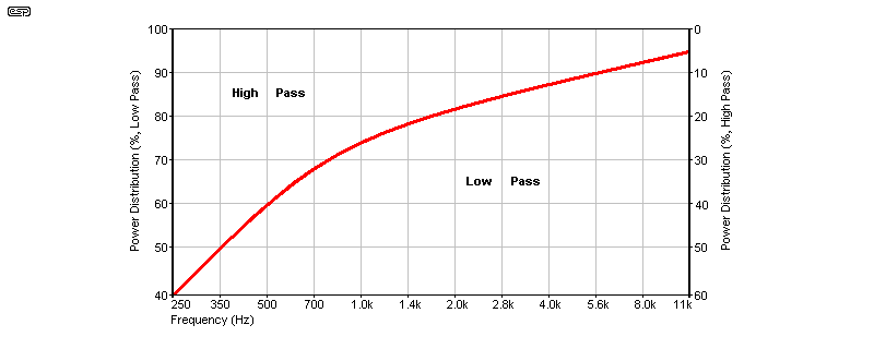
The graph shown above is a reasonable representation of the power distribution between midrange (or mid-woofer) and the tweeter. The levels shown are average and don't consider transients, that's not a limitation, as high-level transients in the upper frequency range are uncommon. For a 100W amplifier with a crossover frequency of 3kHz, 85W goes to the mid-bass driver, and 15W goes to the tweeter. This graph is not (and cannot) be applicable for every style of music, but it's a fairly reasonable (if somewhat conservative) representation of the relative power needs for each driver.
Based on the graph, if we have a 100W amp for mid-bass (or midrange), the tweeter will need around 15W with a crossover frequency of 3kHz. To ensure some headroom, a tweeter amp supply of around ±22V is suggested, which will be able to deliver up to 30W into an 8Ω load. Setting the voltage is easy, requiring only the selection of appropriate zener diodes.
Your first thought might be to use 3-terminal regulators, but they're not suitable. The maximum input voltage for the LM317/337 is 40V, which is only just enough for a nominal 35V supply with a light load and 10% high mains. With a maximum output current of 2.2A (typical, it may be as low as 1.5A) that's not enough to power a tweeter amp to much more than 10W peak. The current can be boosted with an external transistor, but then there's no current limiting without adding more parts.
Should you have a supply voltage of 42V or 56V, then you're out of luck. Yes, high voltage regulators do exist (The TLC783 is an example), but there's no negative equivalent, and output current is limited to 700mA. This is where discrete circuits come into their own, especially if the regulation and ripple aren't super-critical. Accordingly, the regulator shown here is simple, cheap, and more than good enough for the job.
The general idea for a simple regulator is shown in Figure 2. While this will work well, it's less than ideal. In particular, there is no mechanism to prevent 'infinite' current if the output is shorted. In reality, this is very hard to achieve, because the main power supply isn't capable of infinite current. The best we can hope for is that the circuit can withstand a momentary short, although sadly even this is not guaranteed. In the early days of transistor power amplifiers, regulators were fairly common because the amps of the day had very poor power supply rejection. The vast majority had no protection circuitry.
Even though most power amplifiers are now fairly tolerant of supply ripple, it's useful if it can be removed for the tweeter amp. Output current doesn't need to be high, and just 3A (peak) is enough to drive an 8Ω tweeter to well over 25W - far more than you will ever use while ensuring that the tweeter survives. The average will be a lot less, as the peak to average ratio is usually at least 10dB. This means that for a peak power of 25W, the average will only be about 2.5W. Most tweeters are around 92dB/W/m, so 2.5W gives an average SPL of 96dB.

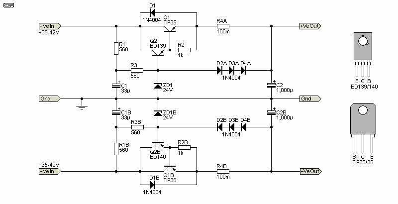
With plenty of gain available from the BD139 ('typical' hFE is 100), the required base current is going to be only around 1.5mA. We always need to ensure that there's enough zener current to ensure regulation, so we'll aim for about 10mA. R1 now can be up to 800Ω in theory, but it can easily be increased to 1k (or more) without compromising the regulator (assuming a 35V DC input). Adding R2 improves ripple rejection. As shown, ripple rejection is about 42dB at 3A output, so if you have 2V of ripple on the +35V supply, the tweeter amp will only see ~34mV. The zener current is well within specifications. Note that adding a cap in parallel with the zener diode does nothing useful, as their dynamic impedance is very low.
The final circuit adds something 'new' to the mix. With the addition of R4 (100mΩ) and the addition of six diodes (three for each supply), we gain some basic limiting ability with the simplest possible circuit. When the voltage across R4 exceeds about 0.4V (4A), the diode string starts to 'steal' base current from Q2, gradually at first, but becoming more effective if current continues to increase. As a current limiter, it's crude, but it works. It's enough to prevent Q1 from seeing a dead short, and it might save the transistor(s) from failing if there is a momentary short-circuit (it also limits the peak current into C2).

You may wish to add a temperature sensor and cut-off circuit if Q1 (A or B) gets too hot. Note that both supplies (+Ve and -Ve) must be turned off simultaneously! Needless to say, this will make the circuit more complex. I expect that most constructors will opt for the basic protection shown above, and it will usually be sufficient provided care is taken to ensure that the regulated supply is never subjected to a sustained overload or a short-circuit. If the heatsink used for Q1 (A and B) gets too hot, use a thermistor circuit to turn on a fan. Q2 (A and B) also need a heatsink, but it needs to be nothing more than a small piece of 2mm aluminium sheet (around 75mm long by 25mm wide should be more than sufficient). Maximum dissipation will be less than 1W, with the average being considerably less.
Using a simplified circuit makes the regulator a great deal easier to build, and it doesn't need a PCB. With care nothing will go wrong once the circuit has been thoroughly bench-tested. Ripple rejection is pretty good, at over 40dB at 100Hz with a 3A load. A more complex regulator can do a great deal better, but there's no need. This circuit is about as simple as it's possible to make a regulator that has at least some protection, and constructors may prefer to use a more rugged series-pass transistor (such as the MJL21143/5 which are rated for 200W dissipation). A continuous short will still cause them to fail, but they are very rugged transistors, even when operated (at least momentarily) outside their safe operating area.
Back in the days when audio power amps used regulated supplies, no form of protection was normally used. An example can be seen in Project 12A ('El-Cheapo' power amplifier), and even when using a germanium series-pass transistor failures were uncommon. For this project, you can also use higher power transistors if that makes you feel any better. They have lower thermal resistance from case to heatsink, so the die should run a little cooler for the same heatsink temperature.
The transistors must be on a heatsink, but in normal operation with music, the power dissipation will be fairly low. If the average tweeter power is (say) 3W for an 8Ω tweeter (which means that the peak current will be close to the maximum), the average current is less than 650mA, so with a 35V input the power dissipated in Q1A/B is under 8W. Surprisingly perhaps, this is still a fair bit of heat to dissipate, especially since that's for each transistor, so the total is 16W. Ideally, the heatsink should not be less than 1°C/W, but you might get away with less.
You may wonder why I don't suggest using a MOSFET as the series-pass device. The reason is quite simple - they aren't suitable. Vertical MOSFETs (by far the most common) are designed for switching, and using them in a linear circuit is asking for trouble. While they don't suffer from second-breakdown, they have a failure mechanism that's almost identical and just as bad, created by 'hot spots' on the silicon die. Almost without exception, manufacturers recommend against using switching MOSFETs in linear applications. They can be used with care, but not at high current. While a lateral ('audio') MOSFET as used in Project 101 could be used, they require a feedback network and are far too expensive for this role.
Any main supply voltage can be accommodated, simply by changing R1. Knowing that the driver transistor and zeners need a current of about 10mA lets you calculate the resistance easily. For example, with a 56V supply and 24V zeners, the voltage across R1 and R2 is 32V. The total resistance is therefore 3.2K, and R1 is 3.2k less 560Ω, which is 2.64k. 2.2k is perfectly alright, and it will dissipate 280mW. I'd use a 1W resistor, as it will run cooler and last longer.
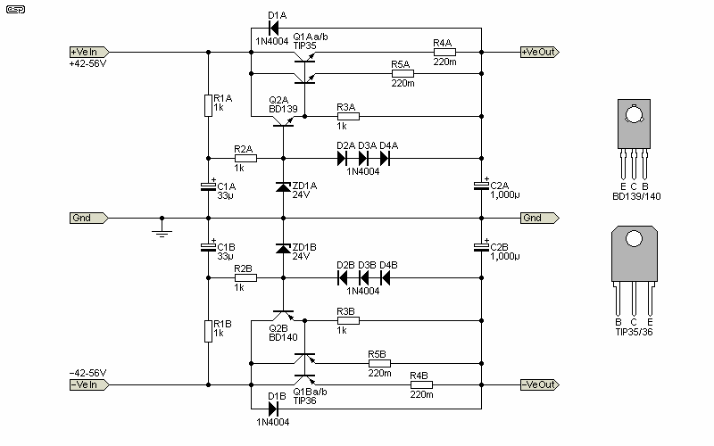
Be warned that with a 56V supply, Q1 will dissipate 270W if the output is shorted, so even the basic limiting will not save the transistor(s). I strongly recommend using two transistors in parallel, and while the driver transistors will dissipate a bit more, they should be alright with a small heatsink. It's unlikely that the TIP35/6 device will be stressed with normal programme material, but it's not worth the risk. With a constant load they definitely would not survive, but music is dynamic, so the average dissipation will (or should) be within the SOA limits of the TIP transistors for 35V or 42V supplies. If your supply voltage is more than 45V, use the circuit shown next, or choose more rugged series-pass transistors.

With higher input voltages, the power dissipated is greater, and for the same conditions as quoted above (3W average into the tweeter), the dissipation rises to a bit over 6W (each transistor) with 42V supplies, and 11W with 56V supplies. This is where you either use parallel transistors (with 220mΩ emitter resistors as shown), or add a separate transformer. There are limits to the amount of heat you can remove from any chassis without a fan, but that is certainly an option. A thermal sensor can turn on the fan if the heatsink temperature exceeds (say) 50°C, which is 25°C above 'typical' ambient temperature.
One thing that you must consider is the main supply voltage change. A nominal ±35V supply may fall to ±30V under load (depending on the transformer's regulation), and this will affect the regulation of the tweeter amp supply. Also consider mains voltage variations (±10% is 'typical', but in reality it may be more). Line (input) regulation is better than you may imagine, with the simulator telling me that the output (at 2.5A) should vary by no more than 200mV as the input changes from 35V to 45V. This is far better than we need, but it comes free. 
The output transistors (TIP35/36) must be installed on a heatsink, and it may need to be bigger than you expect. Suitable thermal interface material is needed, either mica or Kapton, both with thermal 'grease'. I don't recommend silicone pads, but with 35V supplies they might just be alright. In most cases, if the chassis is aluminium of at least 2mm thickness, that should be sufficient to heatsink the output transistors, especially with ±35V supplies.
The driver transistors (BD139/140) should also have a heatsink, but a small piece of aluminium sheet or angle section with a total surface area of not less than 30cm² (75 × 20mm with both sides exposed to the air) should be sufficient. Silicone pads will be fine, as the dissipation is low. In most cases dissipation should be less than 1W, even with full output current.
For more information on heatsinks, thermal interfaces and heat dissipation in general, see The Design of Heatsinks (an ESP article that covers everything you need to know). Another useful resource is Semiconductor Safe Operating Area, which provides information as to why we need to be conservative with the design of circuits using power transistors.
This project offers a simple way to get a reduced supply voltage for a tweeter amp, without the added hassle of another power transformer. The only change that's needed to the basic (Figure 3) regulator for use with higher voltages is to increase the value of R1 and R2, and (preferably) add parallel series-pass transistors with 56V supplies. The regulator has no 'bells or whistles', and is about as basic as it's possible to make while still having acceptable performance. The current limit can be changed by changing the value of R4 (& R5 for parallel output transistors) (A and B). Higher resistance means lower current and vice versa.
The design is deliberately as simple as it's possible to make it. It will never win any prizes for voltage accuracy or current limiting performance, but improving any of the parameters increases complexity, and makes it harder to build. As shown, the complete circuit shown in Figure 3 can be built with a small piece of Veroboard, but with Q1 and R4 (both polarities) hard-wired to provide the best current-carrying capability. Care is needed to prevent any chance of a short circuit, and the tweeter amplifier will typically be an LM3886 (Project 19 or TDA7293 Project 127. Both of these amps will work perfectly with the ±22V supplies this project will provide.
You can increase the supply voltage easily. For example, if ZD1 is increased from 24V to 27V, the output will be increased to ~25V. R1 and/ or R2 may need to be reduced a little to maintain at least 10mA zener current. Also, you need to be aware that the regulation of this supply is not particularly good. It operates open-loop (no feedback) so the output voltage will change with load. Any change is far less than a transformer supply operating under the same conditions, and ripple is also reduced dramatically. The circuit can be used with your main power amps, but the dissipation will be a great deal higher, and you end up with a great deal more heatsinking than you'd need otherwise. No commercial amplifiers use regulated supplies any more, as it's just an extra expense and more things to go wrong.
There are no references, as the design uses basic principles that have been known for decades. The diode 'current limiter' is a technique that's uncommon, but I have used it in other projects I've developed over the years. It's another example of a technique that is (or should be) known to most designers.
Various ESP articles and projects are referenced through the text.
 Main Index Main Index
 Projects Index Projects Index
|