
|
|
| Elliott Sound Products | Project 214 |
The capacitance of a guitar cable (or any cable used with a high impedance source) affects the 'tone' you get. The range of guitar cable capacitance varies from as little as 52pF/ metre up to nearly 200pF/ metre [ 1 ]. Most will be somewhere in the middle, and while around 125pF/ metre might not sound like much, a typical 3 metre lead can have up to 600pF of capacitance when the plugs are included. This still doesn't sound like much, but it can affect the high frequencies you get from your instrument. The effect is generally much worse when the volume control is turned down, as the source impedance is a lot higher. Some cables can generate noise too, caused by what's known as the 'triboelectric' effect, which is only audible with high impedances at both ends of the cable. While this is (mostly) solved by good cable design, it can still be a problem in some cases. A 'cable preamp' makes this (and the loss of treble) go away, due to the dramatically reduced impedance.
The fundamental frequency range of a guitar is from 82.4Hz (low E) up to 1,318.4Hz (high E, 24th fret). Harmonics extend to around 6kHz for most pickups, and this is generally considered to the the upper limit (most guitar speakers roll off beyond ~5kHz). The pickup itself has a resonant frequency, because it's a coil of wire wound around a magnetic polepiece, and there is stray capacitance between each turn of wire. Any capacitance added by the lead can affect the tone, and while this can make it 'better' for some playing styles, it can also make it sound worse.
Guitar Pickup & Wiring Example Circuit, With Impedance Response
The drawing shows the equivalent circuit of a guitar pickup, consisting of a generator (the moving strings), a resistor (the coil's winding resistance), an inductor (the coil itself) and the stray capacitance within the pickup windings and in the control cutout. These combine with the tone and volume controls, and wiring to the output socket. The relative impedance is shown in the graph, and resonance occurs at around 2.7kHz for this example, as shown by the peak. External (guitar lead) capacitance will reduce the frequency and amplitude of the peak, and in an extreme case could remove it altogether (the tone control can do the same). Mostly, this is solved by adding a wee bit more treble boost at the amplifier, but some players may prefer to use a cable preamp to eliminate the rolloff cause by cable capacitance. Naturally, the 'wee bit of treble boost' applied at the amplifier may translate to 'a fair bit of treble boost' if the volume pot is turned down, and the amount of boost needed varies with the volume pot setting. Many players don't like this effect.
Fairly obviously, it's not possible to have a guitar lead with zero capacitance, but you can build a tiny preamp inside the jack plug [ 2 ]. The referenced website shows the general idea, which was developed many years ago (in around 1992). The version shown here uses the same principle, but takes the termination box wiring a bit more seriously for the Figures 2 and 3 circuits. Rather than just using the JFET preamp in the jack plug and having a battery, resistor and a couple of capacitors, I determined the values to obtain almost unity gain, and for Figures 2 and 3, I added an emitter follower that can drive almost any lead length with ease.
Most guitar amps have a 1MΩ input impedance, and that's repeated with this circuit. You can make it higher, but if your source impedance is high, you may have to track down a JFET that has very low input capacitance (CISS. You will need to use an 'oversized' jack plug, as it must house a JFET and three resistors. It's possible to 'hard-wire' the electronics using SMD parts, but they will need epoxy encapsulation to keep everything in place.
The second version goes a step further, and uses a dual supply. This cannot be configured to allow the gain to be changed, as it always operates with a gain of ever-so-slightly less than unity. Some of the ideas used here are adapted from the Designing With JFETs article, which is pretty much a 'must read' before you start. Because JFETs have such a wide parameter spread, you will almost certainly have to select the JFET from a number of candidates, although there is some leeway if you test the circuit first in a breadboard and make adjustments to suit the JFET(s) you have. I was fairly lucky, in that I found an ideal JFET after only three attempts (the moral of this story is that you need to buy several JFETs to get one that works properly).
The optimum VGS(off) voltage for all circuits is around -1.0 to -1.2V, and this should allow the JFET to bias properly. Because JFETs are so variable, device selection and/ or circuit changes are inevitable, so if you're not prepared to hand select the JFET or make changes, there's no guarantee that any of the circuits will work. This specifically excludes Figure 2, which will bias (almost) any JFET properly without you having to do any selection. All circuits shown have been tested using a J113 JFET, and it's one that I know will work very well (selection will still be necessary though).
Note that the preferred connector for the termination box is a 3-pin XLR (J2 in each drawing). As always, pin 1 is ground, and pin 2 is the signal. The Figure 2 version requires all three pins, with pin 3 being the connection to the JFET's drain. There are other connectors you can use, but the XLR provides high reliability and they are readily available everywhere.
Before you start, read the details shown in the Guitar & Bass Pickup Output Voltages article. On average (taken with a variety of guitars and pickups), you can expect a level of between 25 and 80mV RMS, with peaks between 150 and 600mV. The peaks (just as the string is released by a finger or pick) are typically between 15 and 20dB greater than the averaged RMS voltage, and the level tapers off at a rate determined by the guitar itself. Some have more sustain than others, so notes/ chords last longer before disappearing into the noise.
The circuits described here are intended to allow up to 1V peak (around 700mV RMS). It's certainly possible to handle more, but that will almost always mean a higher operating voltage. Few guitars can output more than 1V peak unless played very hard, with high-output pickups and heavy strings. If this describes your setup, then it's unlikely that you'll need a buffer anyway. If you do, then Figure 2 is the circuit for you.
There are a few guitars that have an inbuilt preamp. Some include active tone controls and other 'bells & whistles', while others are simple buffers not unlike those shown here. The disadvantage is that to install a preamp in the guitar means modifications to the body cutout, along with the need to make the battery accessible without eventually destroying the timber where the screws will be removed and installed regularly. Should you get a flat battery during a set, the guitar cannot be used unless you include a means to bypass the preamp.
While this is not my recommendation, any of the preamps shown can be used internally if that's what you prefer. You have to consider the likelihood of possibly serious internal damage if (when) the battery leaks, especially if the instrument is not used every day. The cable preamp has the advantage that if there's a failure, you can substitute a standard cable so the show can go on (as it must).  )
)
The first circuit is very similar to the one described in the first reference. R4 is selected so the output level is almost identical to the original. You may choose to use a trimpot in place of R4, because the gain of the JFET may be unpredictable. All the JFETs I tested gave roughly the same gain (close enough to 0dB), but the first two refused to bias properly to allow 1V peak input. Note that this circuit is inverting.

Figure 1 - Simple JFET Cable Preamp
I've shown the circuit using a J113 JFET, not because they are especially good in this role, but because they are one of the few that are readily available almost anywhere. Because of fairly high input capacitance, the input impedance will fall to around 900k at 10kHz. This is perfectly alright, as it's still far greater than you'll get with even a low capacitance cable. Naturally, if you use a JFET that's designed for audio (or RF), the input impedance will remain at 1MΩ up to higher frequencies. However, you will need to change the values to get sensible operation. With some JFETs it may not be possible to bias the device and obtain the desired unity gain.
There are disadvantages with any simple design of course. The circuit is reasonably tolerant of high capacitance cables, and it will be perfectly alright with anything up to about 2nF (that's very high for a guitar lead, but is still within reasonable limits). The JFET will need to be selected to obtain around 7 - 7.5V at the drain (the positive end of C1). Ideally, you'll be able to verify that the preamp can handle at least 1V peak (700mV RMS) without gross distortion. This requires a signal generator and oscilloscope, but PC-based instruments (using the PC's sound card) will be sufficient if you don't have the proper test gear. My test unit shows distortion to be just under 1% at 1V peak.
Depending on the characteristics of the JFET you use, it may be necessary to adjust the value of R4 to obtain (close enough to) unity gain. If your JFET meets the basic requirement of having VGS(off) of around 1V, the drain current is about 500µA and 1.3V is dropped across the drain resistor. This allows just enough headroom to handle a 1V (peak) signal without excessive distortion.
Measured performance shows that the circuit is 3dB down at 60kHz, driving a cable that I know has fairly high capacitance (around 1.5nF for 3 metres). With a 1MΩ source impedance, the output is predictably half that from the generator (the JFET has a 1MΩ gate resistor). Even with this very high source resistance, response still extends to 20kHz (-3dB). Distortion with 700mV RMS was under 1%, which is quite satisfactory for the intended usage. All of this using a JFET that is cheap and readily available!. The other circuits shown have similar performance, but the next one shown can handle much higher levels.
This circuit has some advantages, but it ideally requires two 9V batteries and it also needs a dual shielded lead (e.g. microphone cable). The biggest advantage is that you can use almost any JFET without any requirement for testing or selection. It will bias the JFET quite happily, regardless of parameter spread or even the type of transistor. There's also one less resistor in the plug, so it may be easier to wire up. You only need to avoid JFETs with a particularly high VGS(off), as some may need more voltage than the batteries can provide. The output is not inverted, and maintains the original polarity if you think that's important.
The basis of this circuit was patented in 1996 [ 5 ], but the patent would never have been enforceable because the principles were already well known (nothing 'not apparent to someone skilled in the field'). For more info on patents, see Patents 101 for DIY Audio Enthusiasts. Since the patent is over 20 years old (the maximum patent protection period), it's now 'public domain' and anyone can use the ideas therein. We'll ignore the contradictions and errors in the patent - they are not repeated here.
Figure 2 - Dual Supply JFET Cable Preamp
With a suitable JFET (and the J113 works perfectly), this circuit can handle up to 7V peak (5V RMS). This is far greater than the output of any guitar, regardless of pickups, strings or playing style. The total current drawn is comparable to that of Figure 1 and Figure 3, being about 3.7mA from ±9V. The performance of this circuit exceeds all others, but at the expense of having to run a 2-core shielded lead to the preamp and the requirement for a higher supply voltage. It can be operated from a single 9V battery (giving ±4.5V supplies), but the JFET's characteristics become more critical.
My tests show that the circuit is flat to at least 40kHz with a 'typical' mic cable. Measured capacitance was 1.2nF from each wire to the shield (measured with a 3 metre microphone lead). My original intention was to use a buffer transistor in a feedback configuration, but the intervening cable made the circuit unstable, so that idea was abandoned. If desired, a simple emitter follower as shown for Figure 3 can be added, and it will not cause any issues.
The frequency response and linearity are considerably better than you can get with the other two versions, and this can almost be considered a 'true hi-fi' cable preamp. It does need a 3-pin connector, but I suggest an XLR connector for all circuits. Neither of the other circuits can come close - even if you use the J113 JFET. Its response is capable of being flat from DC to daylight (well, close enough), with measured distortion below 0.1% with 2V peak output.
In order to get a low output impedance, an emitter follower is included on the JFET circuit shown below. You could use another JFET as a source follower, but it will have much poorer performance. A BJT is more predictable, and they have a higher gain than JFETs. This minimises loading on the drain resistor and prevents a loss of gain. This is particularly important if the termination box is expected to drive multiple amps or paralleled pedals. Like the Figure 1 circuit, this version is inverting.
Figure 3 - JFET Cable Preamp With Emitter Follower Buffer
As always with JFETs, you'll either need to select the JFET or be prepared to modify the circuit to get around 7.5V at the base of Q1. The buffer reduces the output impedance dramatically, and while it's not strictly necessary, this is the version I built for my own use. The drain current will normally be around 500µA as with the first circuit, and the emitter current for Q2 will be about 2.5mA (these are the figures you should aim for by selecting the JFET). I used a J113 JFET, and overall performance is very good.
It is possible to make a preamp lead that can be plugged directly into a mixing console. To make it useful, the output impedance must be very low, so there will be more circuitry inside the phone jack, and the XLR connector will need some circuitry too. This makes the undertaking very difficult without an oversized jack plug, and it's not really something I'd recommend. It's quite simple if the cable will only be around 3 metres long, but if it has to go all the way to a FOH (front of house) mixing console, you may need 50 metres or more, depending on the size of the venue.
If that's what's needed for your application, you'll be better off using a DI (direct injection) box after the termination box with its power supply. The two functions can be combined into a single unit if preferred, and the power for the termination box can be obtained from the phantom supply. This is (I think) an unlikely scenario, so it's not covered at this time. Should there be sufficient interest, I'll have a look at how best to achieve a good result.
The DC input for guitar pedals and other circuits is always a nuisance, because many are designed to use the centre pin for negative rather than positive. This appears to be historical, because when people started making pedals they used PNP germanium transistors, with a positive ground. PNP germanium devices were used because they had better performance than NPN types (this situation was reversed when silicon was adopted as the dominant semiconductor material).
Unfortunately, many DC input sockets have the metal body (which connects to the sleeve of the connector) grounded, so reversal of the input polarity requires the connector to be insulated from the chassis. This is usually harder than it sounds. There isn't any 'standard', so you can easily end up with a mixture of pedals - some with centre-pin positive, others with the centre-pin negative. The circuit below will not blow up if the polarity is reversed because of the input diode, but it won't work until the correct polarity is applied.
I prefer the positive to be on the centre pin, as almost everything else that uses an external DC supply is wired that way, but the choice is yours. The DC input voltage is nominally 9V but 18V can be used for the Figure 2 circuit (see Figure 5). If you use other than 9V, it may be necessary to make adjustments to get optimal performance. I tested my unit with 12V, and no changes were needed, and that's the voltage I'll normally use anyway.

Figure 4 - DC Input & Filtering Circuits (Single Supply Only)
The diodes and filtering shown are required for all variations. The diodes protect against reverse polarity (D1) and stop an external supply from trying to charge the battery (D2). Some DC connectors include a switch to disconnect the battery, but many don't. The diode is easier to install, and there's less likelihood of an error when wiring the connector. The LED and its limiting resistor are optional. The LED should be a high-brightness type, as the current is deliberately limited to about 700µA. The Schottky diodes do introduce a small loss of voltage, but it won't affect operation.
The filter circuit is designed to remove noise from switchmode plug-pack ('wall-wart') supplies. The ferrite bead is optional but recommended - the type suggested is a miniature hollow core of around 5mm long by 4mm diameter. The nomenclature used by suppliers is inconsistent, but the dimensions will help you to find the right one. C2 is a 100nF multilayer ceramic, selected because they have good performance up to very high frequencies. As noted on the drawing, the filter network should be right next to the DC input socket, with very short wiring. C3 (10µF) is located on the Veroboard (or PCB if you make one), and bypasses the supply for the active circuits. This isn't shown on the individual circuits for clarity.
If you use the Figure 2 circuit, you need a different power supply, having an output of ±9V nominal. It can be higher if you use an external supply, but I wouldn't recommend anything more than 24V at the DC input. The circuit will operate with a single 9V battery, but the centre-tap 'ground' (R3, R4, C3 and C4) is needed to provide ±4.5V output. The DC input connector must be fully isolated from the chassis!
Figure 5 - DC Input & Filtering Circuits (Dual Supply Only)
Note that the centre-tap of the two batteries is not connected to earth/ ground. They are wired in series, and the voltage is spit using R3 and R4. The splitter only passes a small current (around 1mA with new batteries), and there is no unbalanced current drawn by the Figure 2 circuit. The only thing that's referred to ground is the JFET's gate, which draws no current.
I'm fortunate to have a supply of large jack plugs that have ample room for the electronics. They aren't particularly handsome, but they are high quality and very reliable. You may (or may not) be able to get something similar, depending on your supplier. The one shown below has the JFET and three resistors installed, with plenty of room to spare. The wiring needs to be done with care though, because you don't need a preamp that dies in the middle of a set because you skimped on insulation or hot-melt glue to keep everything in place.
With the values used in the Figure 3 circuit, the preamp has a gain of about 0.7dB - easily measured, but it won't be noticeable. What is noticeable is the complete lack of treble reduction when the guitar's volume control is turned down. The high frequencies aren't affected at all, and the treble rolloff usually heard is completely absent. There's no doubt that it works, and noise is commendably low (although a very slight hiss is audible at [very] high gain).
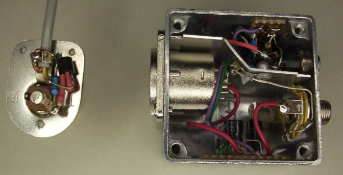
Figure 6 - Test Preamp And Termination Box
My termination box was built using a rather small die-cast enclosure I had to hand. It has no room for a 9V battery, but it won't be used anyway so it's not an issue for my test unit. My playing is limited to the occasional solo session in my workshop, and anything with a battery will end up corroded when (not if) the battery leaks. I used an XLR connector for the preamp lead and a jack socket for the output. I was tempted to use a BNC connector for the output because that's what I use in my workshop for almost everything, but decided against it.
There's nothing critical about the construction of the unit, and I used a couple of tiny pieces of Veroboard for the emitter follower and other circuitry. The DC input is shielded from the rest of the wiring with an aluminium shield, well attached so it can't move to create a short circuit. Because the box is so small, it was a bit tricky to get everything inside, and the photo doesn't show everything. You can see that the XLR is the wrong sex - I used a female plug and male socket. This is so the unit can't be plugged into a mic input which may have +48V on it.
Noise is low, but even with the filtering I used, a slight hum was audible from the two switchmode plug-pack (wall wart) power supplies I tried. I followed the preamp with a laboratory low-noise preamp (Project 158), with a gain of ×100, which is a pretty severe test ... the volume on my guitar was set close to minimum. An 'old school' unregulated linear supply was unusable due to 100Hz hum. The power supply you use is important, and you may need to try a few before you find one that's quiet enough. I tested my prototype with a 9V battery, and measured a broadband output noise of 6µV, which is very quiet (I had to increase the gain of the lab preamp to ×1,000 to measure it). That's pretty good for a JFET that isn't even rated for noise, and is -78dB referred to a 'typical' guitar output level of 50mV (-102dBu).
Using an 'active cable' or 'cable preamp' means that you don't need to worry so much about the cable's capacitance. Nothing can make it go away, but a circuit that reduces the impedance from the guitar's output goes a long way towards making the capacitance irrelevant. Some guitars are more sensitive to cable capacitance than others, and it's common to find that there's a loss of treble when the volume is around the halfway position. Since the 'typical' guitar volume pot is between 250kΩ and 500kΩ, the worst case impedance from the pot itself can be over 125kΩ. This will cause the signal to roll off above 850Hz with just 1.5nF of cable capacitance!
By comparison, the impedance 'seen' by the cable is the value of the drain resistor. If the cable has 1.5nF of capacitance, that makes the -3dB frequency just under 40kHz. There's not much doubt that this is a significant improvement. The input capacitance of the J113 doesn't have as much influence as you may imagine, because R3 (2.2k) in Figures 1 and 3 is not bypassed, so the influence of the gate capacitance is reduced dramatically. A simulation shows that the response extends to 46kHz (not including cable capacitance) with a source impedance of 1MΩ. With a more realistic source impedance of 250k, response extends to well over 100kHz. Ultimately, it's still cable capacitance that dominates the response, but it's effect is greatly diminished.
My preference for a cable preamp is the one shown in Figure 3, and that's the one I built up for full testing. The JFET needs to be selected to ensure it works properly, but because of the emitter follower it has a low output impedance, and can drive several pedals and/ or amplifiers at once. It can also be used with a DI (direct injection) box if a clean sound is required at the mixing desk. The Figure 1 and 3 circuits are inverting, and some players may not like the idea. However, it's highly unlikely that anyone will hear the difference, as our hearing does not depend on absolute phase.
These circuits are not unique in any way, but they are complete designs that I know will work properly because they have been tested and verified. Like all ESP projects, I don't publish anything that doesn't work. Unfortunately, the Net is full of circuits where that is not the case. I've also provided a range of circuits, one of which will (hopefully) suit most players. There's no such thing as a 'universal' circuit that everyone will like, but with three to choose from there's a reasonable chance that anyone who needs a cable preamp (or 'zero capacitance' cable if you prefer) will find one that suits their needs.
 Main Index
Projects Index
Main Index
Projects Index