
|
| Elliott Sound Products | Project 153 |
 PCBs are available for P148 (the basis for this project), as well as P94 ('Universal' Preamp/ Mixer). Please click on the PCB image for the ESP pricelist.
There is a breed of equaliser commonly known as a 'frequency isolator', in that each frequency band can be used in isolation, and the level of each band is adjustable. You can use the unit to provide equalisation, and with variable frequencies you can set the frequency of the bass-mid and mid-high filters to get the sound you want. These 'isolators' are most commonly used with DJ systems, but can be used with any signal source.
In this case, the system described is mono, because it's based on the Project 148 crossover, and as noted in that project you'd need 4-gang pots for a stereo system. These are hard to get, but that has to be left to the constructor. For a stereo system you need two P148 crossovers, and the level controls for each band are normal dual-gang pots.
With the design shown here, you can adjust the 'crossover' frequencies, but there is no reason to change the Q because that will result in an unpredictable overall frequency response. There is at least one commercial 'frequency isolator' that has 'resonance' controls, and presumably that's used to change the filter Q. I consider this to be a really bad idea, so the details are not included here.
You may notice that I refer to this type of equaliser as an 'isolator' (in single quotes) throughout the article, because it does not and cannot 'isolate' frequency bands completely. Commercial units are no different. There are practical limits to how radical you can make the filters before they adversely affect sound quality, and for this reason I have used 12dB/ octave filters. Again, commercial units will be no different.
Commercial 'isolators' may be fixed frequency or variable. Some simply offer a couple of switched frequencies. While you can easily use the Project 09 crossover (configured for 12dB/ octave), it's probable that most constructors would prefer variable frequencies. This does create a problem though, because for a stereo unit you need 4-gang pots to change the frequency. You can make each channel independently adjustable, which might make the system more interesting or more problematical, depending on your point of view.
As noted above, the circuits shown in this article are mono, so you will need two of everything for a stereo 'isolator'. The mixing pots (VR3, VR4 & VR5) as well as the 'Gain Trim' pot (VR6) will then all be dual-gang types. Likewise, the 'Kill' switches (if included) will be double-pole types as well.
For a stereo isolator you need 2 × P148 crossover boards (one for each channel), plus a single P94 'universal' preamp/ mixer board.
Like the P148 crossover this project is based on, it uses a state-variable filter. This is one of the most flexible topologies available but it is comparatively complex, with several separate feedback paths that can make it somewhat confusing to analyse. Fortunately, there are relatively few different component values needed, with only a few deviations that are used to determine the frequency.
Note that all pots shown in the circuit diagrams are linear. Ideally, several of the pots could be anti-log (aka reverse log), but they are hard to get and the curves are usually poorly executed and tracking of dual-gang types is mostly dreadful. Using linear pots is much easier and considerably cheaper, and the result is exactly what's needed in this application.
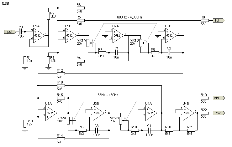
The state-variable filters use U1B, U2A, U2B, U3A, U3B and U4A. U1A is an input buffer, and U4B is an inverter. The inverter is needed to ensure that the three outputs are in phase so that the next stage (a summing amplifier and inverter) will provide a flat response when all level pots are set to the same position - typically 12 o'clock for flat response. For a more in-depth look at the state-variable filter itself, see the Project 148 article.

Figure 1 - State-Variable Filter Circuits
The Q can be changed without affecting gain by adjusting the value of R3/ R13. As shown, Q is 0.5, so the filter has a sub-Bessel (Linkwitz-Riley) response, with the two outputs 6dB down at the crossover frequency. This is exactly what's needed for an equaliser, and different Q values will cause response anomalies. Ideally, R3 & R13 should be 11.2k (exactly double 5.6k), but using 12k as shown causes less than 0.3dB frequency error when the three outputs are summed.
With a dual 20k pot and other values as shown, the low-to-mid frequency can be set anywhere between 68Hz and 480Hz. The range can be extended by reducing the value of R17 and R18 (3.3k), but making the value too small is not recommended. If reduced to 2.2k, the frequency range is from 72Hz up to 723Hz. The mid-to-high frequency is variable from 680Hz up to 4.8kHz, and the range can be changed in the same way as for the low-to-mid section.
Although it's far better if the two gangs of each frequency pot track perfectly, a small error won't generally cause a problem. In most cases, the tracking should be good enough to ensure that the summed output response is flat to within 0.5dB or better. If C3 and C4 are reduced (or C1 and C2 for the mid-to-high section), the crossover frequency is increased.
The crossover frequency is determined by the value of the capacitor and series connection of the pot and R7 (R17) and R8 (R18). Calculating the frequency uses the traditional formula for a resistance/ capacitance filter, so with the values shown for the low-mid filter and the pot at maximum resistance (20k + 3.3k), the frequency is ...
f = 1 / ( 2π × R × C )
f = 1 / ( 2π × 23.3k × 100n ) = 68.31 Hz
You can change the frequency range by changing R6 and R7, and/or C1 and C2. Both resistors must be the same value, and likewise for the capacitors. Use the above formula to calculate the frequency for any R/C combination at various pot settings. For an 'isolator', the frequencies are pest determined by ear, because there is no technically 'correct' setting.
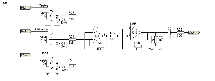
The final part of the 'isolator' is the mixing stage, followed by an inverter. The point of the latter is dubious because there is a significant phase shift through the filter circuits, so it can be omitted without changing the sound. The frequency where there is zero phase shift (after the inverter) is 600Hz with the frequencies shown, but it will vary depending on the frequency pot settings.

Figure 2 - Summing Amplifier & Inverter
The three 'Kill' push-button switches are optional. These allow you to drop the level to zero instantly. There is going to be a slight click when the switch is operated, because it will reduce some arbitrary signal level to nothing in a microsecond or so. This will normally be done 'on beat' and should not be audible to the listeners if your timing is good enough.
The 'Gain Trim' pot allows you to adjust the gain through the 'isolator', so you can ensure that the level doesn't change when it's patched in or out. With the values shown, the range is from -6dB, 0dB (close enough) with the pot centred, and +3.5dB at maximum gain. The gain settings are within 0.5dB, provided the pot has a true linear characteristic.
With the values shown above, the gain will be unity when the three pots are centred (12 o'clock position). The maximum gain is 9dB with any (or all) pots at fully clockwise rotation. Each frequency band can be reduced to zero - commonly referred to as 'infinity' in 'isolator speak'. Note that if any level pot is set for zero, it cannot eliminate the frequency band completely. All frequency bands are similarly affected, and the response 'tapers off' rather than being 'isolated'.
With any filter there is a rolloff slope, and it's unrealistic to expect any filter to be able to completely remove a wide band of frequencies. Regardless of what you might hear, read or see claimed, true frequency isolation simply isn't possible while retaining any pretense of being usable for audio (see note below).

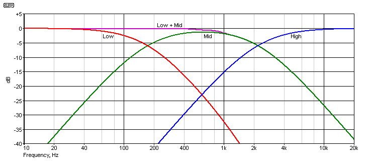
Figure 3 - Frequency Response Of Filters
The response of the filters is shown above, with the frequencies set for 170Hz and 2.2kHz for reference. The effect of turning off the high frequency is shown in violet so you can see the response - the same effect will be seen if the bass is turned off. It's quite easy to see that if the high or low band pot is set to minimum, the signal sill be rolled off following the midrange slope. For example, with the bass pot set to minimum, the signal will be about 12dB down at 100Hz, 22dB down at 50Hz, etc. It's basically the same story with the treble control, which for the filter frequencies shown will be 15dB down at 5kHz. Turning off the midrange is less pronounced, and will result in a -17dB notch at 600Hz. The frequency and notch depth will change as the filter frequencies are modified.

| Note: It's certainly possible to totally remove a band of frequencies with nothing remaining at levels greater than -60dB or so, but the result would sound
truly horrible. The filters needed will also be very complex, and while an analogue solution is possible it would be easier and cheaper to use a
DSP than to attempt it with traditional opamp filters. Removing a single frequency is easy - it's called a notch filter and is the basis of most distortion analysers. However, this truly is a single frequency, and anything even a few Hz either side of the notch will get through to one degree or another. Using notch filters would be silly and pointless (but they have been used anyway), unless you have a 50/ 60Hz hum problem - this is one area where such filters are used routinely, because they have so little effect on the rest of the signal. |
Please be aware that you have to be very careful if you boost the high frequency range. Although the maximum gain is only 9dB, that may be more than enough to cause the high frequency horn/ tweeter great distress. DJ operators are known for being especially tough on equipment, and the use of radical equalisation such as that provided by an 'isolator' can cause power amp overload, speaker failure, or (if you are lucky) just seriously distorted output. The punters may or may not notice, but they will be aware if you cause the system to fail by overly exuberant use of EQ.
The mixing amp and inverting buffer can be implemented with the Project 94 'universal' preamp board, and the PCB for that is available. There is also a PCB for the state-variable crossover Project 148, but as noted earlier the P09 crossover can be used if you are happy with fixed frequencies.
It's important to understand that the term 'isolator' is basically wrong, and the idea of 'infinite' reduction of any frequency band is rather silly. All 'isolators' are made using circuitry that is very similar to that described here.
As noted in the introduction, it is also possible to use the P09 crossover instead of the state-variable, but (of course) with fixed frequencies. 400Hz and 4kHz seem to be popular, but you can select the frequencies that suit your preferences. Using it with the default 24dB/octave filters isn't recommended because in isolation they can sound very artificial because of the very steep rolloff slopes.
At most settings that will be used and with typical input and output voltages, distortion can be expected to be well below the limits of audibility, and depends to some extent on the opamps you use. Most of the component values have been selected based on the use of NE5532 opamps - still one of the best audio opamps you can get. You can also use TL072 opamps if you want, and they are fine for a budget system. Top-of-the-line is the LM4562, but they are quite expensive and it's doubtful that you will hear any difference whatsoever in a double-blind listening test.
It's probably worth pointing out that this general arrangement was used in mixers I designed along with a friend well over 35 years ago, but they were intended to allow the system to be set up properly and were never used as a sound effect.
 Main Index
 Projects Index