
|
|
| Elliott Sound Products | Project 152 - Part 2 |
 Main Index
Projects Index Main Index
Projects Index
|
Part 1 of this project covered the input stages, equalisation, and the overload detector. Now we'll look at the compressor/ limiter, crossovers and power amp drivers with their 'soft-clip' circuits. The tuner output and effects send and return circuits are also covered, along with stereo operation. There's also the balanced output intended for the front-of-house PA mixer, or for recording. This can be switched to be pre or post EQ, because in many cases the sound you want on stage is not the same as that needed by the mixer, and your 'stage EQ' might be a bit radical for the PA system or studio mixer.
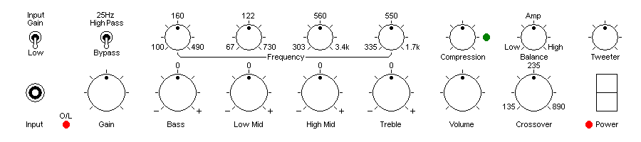
The drawing above is the same as that shown in Part 1, and is included here as a reminder of the many facilities included. Many of the controls discussed will be on the rear panel, and these include the effects insert jacks, balanced send, pre/ post EQ switching, tuner output and the main outputs (assuming the unit you build is a preamp). Otherwise, the speaker outputs will also be on the back panel, and as discussed below, I recommend that only Speakon connectors are provided.
There is also an essential discussion about power output and speaker sensitivity.
The tuner output simply connects to the points marked 'Tuner' on the preamps. The level and impedance are the same for both preamps, so it really needs no further discussion. The effects send and return aren't any more difficult, and it's done with a switching jack for the return (which can also be used as an input) that disconnects the internal signal when the plug is inserted. The send and return jacks are wired as shown below.
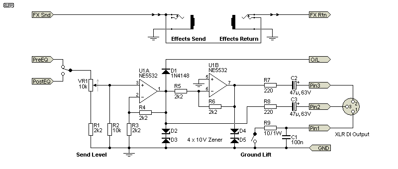
The DI (direct injection) connection is balanced, and the level can be varied with the pot. The circuit is very straightforward, using one half of an NE5532 as a buffer (with 6dB of gain), and the other half as an inverting buffer. The opamp outputs are isolated from the cable with 220 ohm resistors to prevent possible oscillation.
Protection from external 48V Phantom power is necessary, and is provided by the 220 ohm resistors and 10V zener diodes ¹. If a lead is plugged into the DI output with phantom power turned on, the cable capacitance is charged to 48V and the discharge current can easily damage the opamps. The 220 ohm resistors limit the worst case peak current to a little over 200mA, and the zener diodes ensure that the energy is dissipated harmlessly.
Pin 1 (ground) of the XLR is lifted from the system earth/ ground by means of a 10 ohm 1W resistor and a 100nF capacitor to provide some isolation from earth loops that may cause hum. For cases where this isn't enough, there is also a ground lift switch.
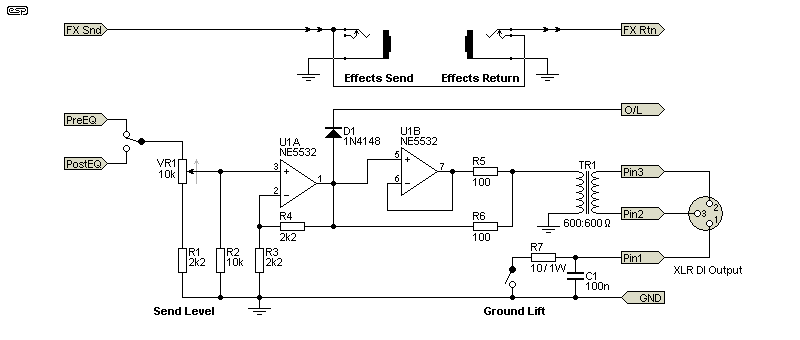
There are ICs that provide close to a true 'floating' output, and the circuit is described in Project 87. However, I don't really recommend that you build this form of balanced output circuit. I've tested the scheme and it works, but I have reservations about using it in a stage environment. Protection is harder and it is less effective than might be imagined. I suggest that if you really need a floating output, use a transformer as shown above. Depending on the transformer used, it may be necessary to reduce the value of R5 and R6. Do not use values lower than 10 ohms.
This is always hard. While commercial VCAs can provide very wide gain control with distortion consistently far less than 0.5%, most bass amps use a JFET as the gain control element. While dramatically cheaper than any VCA, these have several limitations. The voltage across the JFET has to be kept low or distortion becomes very audible, and the low voltage means more gain is needed, so noise is increased. JFETs also vary widely, even within the same batch of devices. It's often necessary to include a trimpot to set the correct operating point, and there's also a high impedance network needed in the gate circuit to minimise distortion. Most modern bass amps seem to use a JFET based limiter, and some are ok, others I consider marginal because of relatively high distortion (as much as 7% is common).
An LED/LDR optocoupler (as a manufactured item or DIY) can handle several volts RMS with almost no distortion, but the LDR always has an attack and decay time that depends on the light sensitive material composition. Fortuitously, the timing is usually almost perfect for most instruments without you having to do anything.
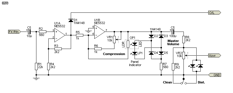
The circuit is shown above. Once the level is high enough to turn on the LED in the optocoupler (OP1) and LED1 (panel indicator), the resistance of the LDR falls, reducing the gain. Considering that many of the most highly regarded vintage studio compressors and limiters used an LDR with some form of illumination (filament lamps, electroluminescent panels or LEDs), some degree of 'street credibility' is assured.
While it might be called a compressor/ limiter, in most cases the circuit in commercial amps is really a peak limiter. The circuit shown here is no different, largely because it is significantly easier to create a limiter than a compressor, and most of the time you need a limiter anyway. While it might look like I've cheated by simplifying the circuit to the extent shown, I've tested the compressor/ limiter with off-air programme material from FM radio, bass guitar, 'ordinary' guitar and tone burst signals. There is no evidence of distortion, mainly thanks to the NE5532 which can provide far higher (undistorted) output current than most common opamps.
The optocoupler can be a 'proper' Vactrol VTL-5C4 (for example) or similar, or you can make it yourself. Project 200 has detailed instructions for making your own LED/ LDR optocouplers. This type of gain control device is ideal for the job, because they have very low distortion compared to JFETs, and can tolerate much higher signal levels.
The output level is set by the LED voltage drops, plus two diodes. It is fixed at 3V RMS (sinewave) or about ±6V peak with programme material, and can handle an input voltage of up to 1.5V (RMS) for no compression with the compression pot set to minimum resistance (minimum compression). Note that the panel LED must be a high efficiency/ high brightness type. I suggest a minimum of 1,000mcd (milli-candela), with around 1,500mcd being preferred. Because of the sensitivity of the Vactrol I used for testing, a normal LED (usually less than 100mcd) will not be visible, even at full compression.
Just below the compression threshold, the distortion measured less than 0.1%, and that rises to about 0.6% with 1.5V input and maximum compression. Distortion is almost completely third harmonic, with no high-order harmonics or evidence of opamp distress.
If you want to get a 'dirty' bass sound, then the distortion facility is worth including. Much like a guitar amp, you turn up the input Gain and/or Compression control, and turn down the Master Volume. Distortion is generated by a pair of green LEDs, and the circuit shown above will maintain a fairly consistent level as distortion is switched in and out. The level needed is around 1.6V RMS to obtain 5% distortion. As the level is increased, so is the amount of distortion. It's also worth noting that using distortion also provides a level of compression (or peak limiting to be more accurate). Once the level is set, as you play harder (and therefore louder), the volume doesn't change very much, and as a note decays the volume remains much the same until you 'run out' of distortion. The compressor helps to limit the degree of 'dirt' generated.
The variable crossover used to divide the signal between the two power amps does not need a high rolloff slope, and in fact a gentle rolloff is highly desirable. We aren't trying to limit the power delivered to a tweeter, we just want to divide the signal between two cabinets, both of which can cheerfully accept the full range signal anyway. The ideal is a first order (6dB/ octave) filter, which is not only easy to accomplish, but sounds 'right'.
Listening to a suitable candidate, I figured out that the crossover frequency range needs to be from about 150Hz to 850Hz, which is easily done with a dual gang pot plus a couple of resistors and capacitors. However, using a 1st order state-variable filter means that only a single-gang pot is needed, and the opamps are required anyway. First order state-variable filters are not common, and this may well be the first time you've seen one. As is the case with all first order filters, the Q cannot be adjusted, but the outputs sum to a flat response.
The frequency range can be much wider of course, but the extremes will almost certainly never be used so there's no real point. While it's certainly possible to make the crossover more elaborate, I can't think of a single good reason to do so. I have seen a second order state variable filter used for the crossover (12dB/octave), but it's simply not necessary because two (nominally) full-range cabinets are being driven. However, the option is shown below if you think that a 12dB/octave filter is needed.
The idea is to use a 10k pot with a 1.8k series resistor, and a 100nF capacitor forming an integrator using U2B. This gives a crossover frequency range from 134Hz to 885Hz, but you can change the range easily by using a different cap (and/or pot) value. The 6dB/octave state-variable filter buffers the outputs so the balance control doesn't affect frequency response. The balance control means that you can adjust the level that goes to each box, and this provides an additional tone shaping network that can be used. It's expected that the two power amplifiers will be of equal power.
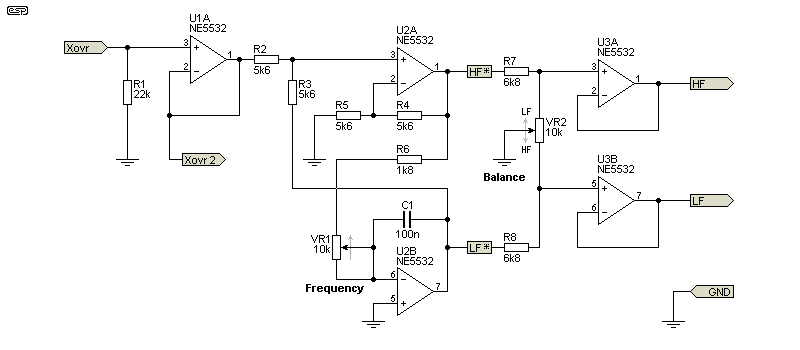
If you wish to expand the frequency range, simply use a larger value pot and a smaller capacitor. For example, a 50k pot and a 47nF capacitor gives a range from 65Hz up to just under 1.9kHz, but that is too radical and unlikely to be useful in practice. I leave it to the constructor to decide just how much range is needed, but I expect the default using the recommended values will suit most players.
The balance control has been designed to ensure that with the pot centred, the output from each section is 3dB lower than if the pot is set for one channel or the other. This maintains the power at a reasonably constant level regardless of the pot setting. The 'Xovr2' terminal goes to the horn filter shown in Figure 15.
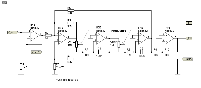
The circuit seen above can be used instead of the first order crossover shown in Figure 13. This is only the crossover, and the points marked 'HF*' and 'LF*' connect to the corresponding points in Figure 13. The frequency pot must be a dual gang type, and an additional dual opamp is needed. The remaining circuitry (the balance control) is not changed, only the crossover network. I doubt that there's any advantage to using the 12dB filter, but feel free to use it if you prefer. The frequency range is unchanged, but if you wish to modify the range you can do so in the same way as described for Figure 13.
The second crossover (for the horn, if used) needs a fast rolloff to protect the driver. There is no provision for a low pass section for the main speakers, as the horn is used only to augment the top end. The main speakers will be allowed to roll off naturally. Of course, this will provide some colouration to the sound, but that's exactly what's needed. The high pass filter has a -3dB frequency of 2.47kHz as shown, and has a slope of 18dB/octave. Note that the IC (U1B) is the second half of U1 in Figure 13 or Figure 14.
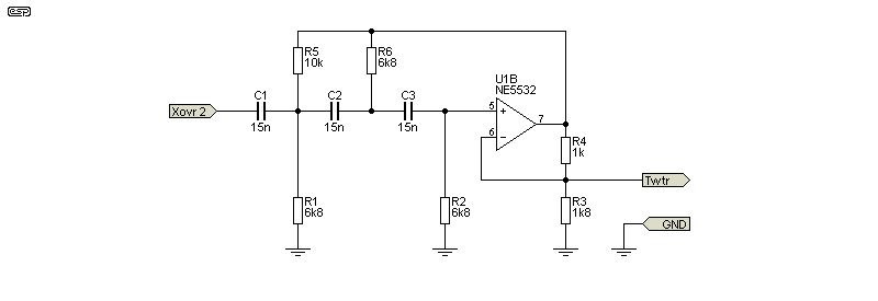
This filter is 18dB/ octave, and has a modest gain of 4dB. The gain is added to improve the Q of the filters without resorting to a collection of odd value resistors and capacitors. The signal is taken from the feedback network rather than the opamp's output to restore unity gain.
It's not a classic Butterworth or Chebychev filter, but there is a slight rise (0.65dB) before rolloff. The filter is tweaked to get a slightly faster initial rolloff than is normal with a simplified circuit using equal value resistors and capacitors. If you want to provide some extra protection for the compression driver, just reduce the cap values from 15nF to 12nF, which will raise the -3dB frequency from 2.47kHz to 3.94kHz. Using 10nF increases the -3dB frequency to 3.72kHz, and although this is much safer for the driver, it may not give you the top end you need.
Naturally, if the capacitor values are increased, the frequency is lowered. Using 18nF will reduce the -3dB frequency to 2.06kHz, and 22nF gives 1.68kHz. The frequency you use must match the compression driver and horn. It's also worth noting that the use of a separate amp means the system is not designed for use with piezo horns. These present a capacitive load and should never be the only driver connected to an amplifier, or the amp may oscillate and destroy itself. The consensus is that piezo drivers don't sound very good anyway, so there's no great loss.
All horn compression drivers are easily damaged by excess power, low frequencies and (especially) DC, so it's highly recommended that you include a series capacitor for the driver to protect it. You'll need a 10-15uF capacitor for an 8 ohm driver, and the cap should be a motor start or other AC rated non-electrolytic type. Bipolar (non-polarised) electrolytic caps are not recommended because they are not stable over time, and often can't handle the current that they are expected to pass.
With the cap in series with the driver, the ultimate rolloff will be 24dB/octave. If you think this might be a bit too severe, the first stage of the tweeter high pass filter can be omitted. This brings the ultimate rolloff back to 18dB/octave, but it will only be 12dB/octave until the frequency is low enough for the series cap to take effect. What you do here is largely determined by the driver and horn, so adjustments will be needed.
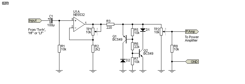
There are now three separate outputs - 'LF' (low bass), 'HF' (high bass) and 'Twtr' (compression horn 'tweeter'). Each goes to a separate amp and speaker(s), each via a final stage that provides the soft-clip distortion circuit (if desired - in many cases constructors may prefer clean outputs from all outputs).
You'll need three of these circuits for a 2-way active system with tweeter horn, and distortion is generated by either four green LEDs or a transistor-diode circuit in series-parallel after the final opamp. The level needed with green LEDs is around 3.2V RMS to obtain 5% distortion. As the level is increased, so is the amount of distortion. This is independent of the distortion available from the compressor circuit, and the output level is set with trimpots to suit the power amps you will be using. You need an oscilloscope for setup, but a PC based version will work well enough provided you use a variable attenuator at the input to prevent overload.
The 'secret' to getting a good soft-clipping characteristic is to use a low value resistor in series with the diode string. In this case, the feed resistor is only 220 ohms, much lower than you'd normally expect to see. It could be even lower, but then two NE5532 opamps in parallel might be needed. 220 ohms is actually quite a good value, and it matches the dynamic resistance of the diodes well enough to get a very smooth overload characteristic. This is assuming that the opamp gain and output levels have been set fairly carefully though.
Set all tone controls set to flat, Compression at minimum and Master at maximum. Then apply a signal to the input, and adjust the level until the compression LED just starts to illuminate. Reduce the setting of TP2 to ensure that the power amp you are using is well below clipping. Adjust TP1 until the output waveform shows moderate distortion, but no 'hard' clipping. Now, set TP2 until the power amp is just below clipping. During normal playing, the output should start to sound a little 'dirty' at around 80% power, and will get progressively more distorted as the power amps(s) approach clipping. The transition into clipping should be barely noticeable.
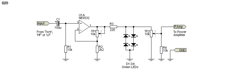
The trimpots shown before and after the final preamp are so you can set the level to match the power amp(s) as described above. Ideally, the trimmers will be set so that the clipper circuit is operating before power amp full power. For example, if the power amp needs 2V RMS for full output, the soft clipper will have around 10% distortion with a 2V output. The power amp can easily be driven to full power, but the onset of distortion will be gradual rather than instantaneous.
Activating the distortion will not trigger the overload (clipping) indicator. Note that the way you set up the soft clipping circuits is very personal, and you may want the signal to start distorting only a few volts shy of power amp clipping, or much earlier. The trimpots are a nuisance, but they are essential to allow you to adjust the circuit to get the results you want, rather than having it set for some fixed level that doesn't suit you or your playing style.
If you use a valve amp, there is no control over the distortion produced prior to clipping. In contrast, the circuit shown here lets you experiment until you get the maximum undistorted output with just the amount of distortion you want. Needless to say these circuits can be eliminated altogether, and the power amps driven directly from the crossovers. Note that you may need the gain stage shown here though, because there might not be sufficient level from the balance circuit to get full power from the power amplifier(s).
An alternative version of the soft clipper is shown above. It's more complex, but the dynamic impedance of the clipping circuit is higher so the effect is a little 'softer' than the one shown in Figure 16. The setup process is the same as for the first version. The two diodes are 1N4148 or similar. To get a slightly harder clipping effect, reduce the value of R6 (22k). With the values shown, the distortion is a bit under 6% at 2.2V RMS output. This will work well for any amplifier from the ESP selections running with up to ±56V DC supplies (180W into 8 ohms or about 350W into 4 ohms).
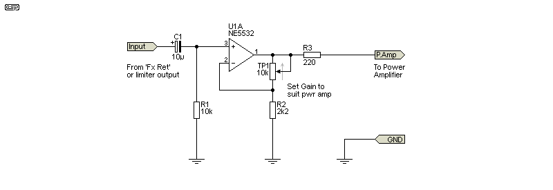
Finally, the above shows the simplest possible output amp. The trimpot lets you set the gain, which depends on the power amplifier. This is intended to let you set the final gain so that the master volume control is normally set to around 50-75% for full output. Because many power amps have different gain (nearly all ESP designs use a gain of 23 - 27dB), you do need to be able to adjust the final gain stage if the power amp used has different input sensitivity. The input to this stage will normally come from the output of the limiter circuit (Figure 12), but if this isn't used, it will come directly from the effects return socket.
Use of stereo bass amps was quite popular a while ago, but seems to have fallen from favour. If you do want a stereo rig, you are going to need two preamps. They don't have to be identical, and you won't need the variable crossover. You will probably want to use a horn 'tweeter', but that only needs to be part of the preamp for the bridge pickup, because that's where most of the treble comes from. There are so many possibilities that it's not sensible to try to describe them all, so how you go about it is largely up to you.
It might be possible to use only part of the EQ section for each channel. For example, you could use the low-mid parametric in the bass channel, and the high-mid parametric section in the treble channel, but include bass and treble controls (variable of course) in each preamp section. The compressor/ limiter is a bit trickier, as you might want them to track, or you might decide to use an independent limiter for each channel - or you could switch between the two. This isn't quite as easy as it sounds though, because any two LED/LDR opto-attenuators can be quite different from each other.
Otherwise, the circuitry will be pretty much as described, except there will be two preamps, simplified or complete. I would expect that the balance control isn't needed, as most of the tonal balance will be done 'on the fly' using the controls on the bass itself.
The tweeter amp is easy - use P27A (100W guitar power amp), and use an 8 ohm compression driver and horn (not piezo). This combination will deliver at least 60W, so the compression driver you use must be a high power type, with a throat not less than 38mm (1½") to minimise distortion. Alternatively, you can use a lower voltage for the amp to reduce the power. Use a good quality film capacitor in series with the compression driver to prevent possible problems with DC if the amp fails. I suggest not less than 20uF, which means a motor start type capacitor. They are comparatively cheap compared to 'traditional' PCB mounting capacitors, and are very rugged.
Power amps for the bass section will be more complex and expensive if you think you'll need high power. Since most bass rigs have an inbuilt DI box and send a signal direct to the mixer, you may find that high power isn't actually needed at all. Of course this depends on many factors that only you know, such as playing style and what you wish to achieve. It also depends on the efficiency of your speakers. More efficient loudspeakers need less power to make the same noise as a low efficiency version, and just a 3dB improvement means you only need half the power. It might transpire that you only need a pair of P27A power amps (100W into 4 ohms) to get as much sound on stage as you need. Naturally, you might also need a great deal more, and that leads us into one of the more complex issues you face with high power amps and speakers.
At this stage, I don't have any plans to produce a design for a new power amp. There is already a project that is suitable (see Project 68), except it does not have protection circuits. This places the amp at great risk if used for bass guitar, because of the proliferation of jack sockets on speaker boxes. If the plug is inserted or withdrawn while the amp is on, the output will be shorted, and if that happens under load the amp may blow up. This problem can be all but eliminated by using Speakon connectors on the amp and speaker cabinet.
An alternative is Project 101 - the lateral MOSFET power amp. Just by the way they work, lateral MOSFETs are self-protecting, at least to a degree. I never recommend deliberately shorting the output of any power amp (including those with short-circuit protection) because there is always some risk. With the MOSFET amp that risk is reduced though.
The only speaker connections I recommend are Speakon types. 'Cannon' (aka XLR) connectors are reasonably safe, but the Speakon is now sufficiently popular that you can buy ready-made leads and there's no reason to use anything else. Phone jacks and sockets are the legacy of a bygone era, and there is no place for them in modern equipment. Note that it is imperative that Speakon connectors are used on the speaker cabinets as well as the amp. Many guitar and bass cabs use jack sockets, but they nearly all create a short circuit when the plug is partially inserted! Change them to Speakons - you'll be glad you did. Apart from the safety of your amp, they can't just fall out if someone trips on the lead during a gig.
One thing you must consider for a power amplifier (whether internal or external) is the power handling of the speakers. Most manufacturers fail to tell you everything you need to know, and there are many myths as well. One of the most important parameters is excursion-limited power handling, and this is not something that most speaker makers will tell you. The limit depends on the type of enclosure (sealed or vented), and varies with frequency and the box size and tuning. A great many speakers (including those rated at over 500W continuous - in someone's dreams perhaps), will reach their excursion limits well before the rated power is reached.
When you play, any noises from the speakers themselves (typically described as 'farting') indicate that you have gone past the limits, and risk damaging the loudspeaker if you don't reduce the volume or bass boost. Amplifier clipping is also audible, but it's usually fairly easy to pick whether the distortion is from the speakers or the amp. For starters, look at the cone - if it is moving so far that it distorts the cone itself, you will ruin the speaker very quickly. You also have to consider the thermal limits of the speaker drivers. It's not at all uncommon for speakers to be rated for many hundreds of watts power handling, but that doesn't mean that's how much power you can actually push into them.
It's worthwhile having a look at the info at BareFaced Bass [ 3 ]. There is no affiliation and this is not a specific recommendation, but they are one of the very few who explain the relationship between power, excursion and thermal limitations. I make this suggestion solely in the interests of the reader knowing a bit more about what you can and cannot get away with, and what you can do to absolutely destroy a speaker - i.e. use the common 'rule' that the amp needs to be much more powerful than the speakers for 'headroom'. Do not accept the myth that speakers are blown up because the amp is too small. Even speaker makers will regurgitate this drivel, and it's totally false in over 95% of all cases of speaker failure.
The idea of amplifier 'headroom' is beyond being silly - it's so entrenched as to be dangerous. Contrary to popular belief, pushing an amp into clipping is not what blows up the speaker. The real cause is sustained maximum power because an amp that's clipping has reduced the dynamic range and raised the average continuous power level. There is a great deal of nonsense about the harmonics of a squarewave being the cause of speaker failure - this is complete bollocks! Please read Speaker Failure Analysis for detailed information.
This is especially true for instrument speakers! A 100W amp driven into full squarewave output can deliver close to 200W, and the power is often continuous and unrelenting. This can burn out a speaker, and that's why guitar amps (for example) should use speakers rated for double the amp's power rating. This usually doesn't apply to bass because few bass players use full overdrive, but using an amp that can deliver far more power than the speakers can handle is a recipe for failure.
With speakers, there are essentially three major attributes (sometimes called "Hoffman's Iron Law") - sensitivity, small size, low frequency. Pick any two! The laws of physics are heartless, and despite many claims, cannot be defeated by advertising copy. This means that you can have a speaker system that's small and sensitive, but don't expect it to be any use for a bass guitar. You can have good bass extension and high sensitivity, but it most certainly won't be small. All bass cabinets are a compromise, trading off the parameters to get something that will work well enough but still be portable.
If a speaker is rated at 95dB/1W/1m (and that's pretty good for a bass speaker), its efficiency is 1.95%. That means that 98.05% of the total power delivered by your amplifier is converted to heat, not sound. At high power levels the voicecoil heats up and increases its resistance, and the total efficiency falls even more! Power compression is a very real phenomenon, and it's not too difficult to create a situation where you double the amp power expecting 3dB, but find that at continuous high levels, you can't even hear the difference, because it may be only 1dB or so. The remainder is converted to heat, and the speakers will probably fail as a result.
It's important to remember that if one speaker is 3dB more efficient than another, that's the same as using double the power. So, all other things being equal, if you have a 200W amp and the choice of two speakers with one being 93dB/1W/1m and the other 96dB/1W/1m, the lower efficiency driver means that you'll need to use an amp of twice the power (400W) for the same SPL. Not only will the amp be more expensive, but the poor speaker will have to dispose of over 390W of heat. Higher power and lower efficiency makes the situation worse. Also, be aware that some loudspeaker driver manufacturers rate the sensitivity using 2.83V RMS ... for both 8 ohm and 4 ohm drivers. No problem with 8 ohm speakers, but 2.83V gives 2W into 4 ohms, so the sensitivity figure is artificially inflated by 3dB. Make sure that you read specifications very carefully.
In general, it's far better to choose speakers that have high sensitivity at the expense of power handling. A 100dB/1W/1m speaker rated at 100W will be significantly louder (and will suffer far less power compression) than a 90dB/1W/1m speaker rated at 1,000W. Unfortunately, the laws of physics insist that it's very difficult to make a speaker very sensitive yet still have good bass extension, and it will need a large cabinet. The driver you choose has to be able to reproduce the lowest note from your bass - either 41Hz or 31Hz, and this can be a real challenge. You can drive a speaker in a sealed cabinet below resonance, but efficiency is poor, you need stupid amounts of power, and cone excursion can become extreme.
Sub-resonance operation works very well for hi-fi system subwoofers, because the average power demands are very low. This is not the case for a bass amp though, which will be called upon to deliver plenty of power (and SPL) for an extended period of time. Getting the highest efficiency possible is necessary to reduce the overall power needed, which in turn minimises power compression and ensures the driver(s) will have a long life.
By adding a compressor/ limiter (or generally just a peak limiter) around the power amplifier, we can prevent sustained clipping. Unless the limiter is very fast, there will nearly always be a small amount of clipping on the initial transient, but this shouldn't be audible if the limiter is reasonably fast. What is 'reasonable' in this context? In general, a LED/ LDR limiter as used in the preamp is fast enough, or a JFET limiter can be used that is a great deal faster. Allowing initial transients to clip isn't usually a problem, and if done carefully can give the bass an 'edge', giving those transients some 'bite' that many players like.
Any form of limiter always has to be used with caution though, because it's easy to increase the average continuous power level to the point where speakers may suffer distress, overheat and possibly fail. This is why it's so important to understand the relationship between amplifier and speaker power, and use enough speakers so they can handle the power output without 'blowing up'.
| Main Index
Projects Index
|