

|
| Elliott Sound Products | Project 150 |
The main purpose of this article is to introduce the reader to a flexible equaliser circuit that can be used for hi-fi, mixing consoles, instrument amplifiers (especially bass guitar) or anywhere else that a simple and predictable 'parametric' equaliser is needed. It's not perfect (I don't know of any circuit that is), but it is fairly simple to implement and performs well.
Parametric equalisers are often very complex, because to enable variable frequency and Q requires a state-variable filter. While other filter types can also be used, most are not as well behaved or as flexible as the state-variable topology. However, there are many places where the ability to vary the Q is not needed, especially for general purpose tone controls.
For musical instrument use a flexible tone control circuit is often a must, and especially so with bass guitar which has some interesting challenges. I have already described a 'quasi-parametric' equaliser (see Project 28), and it does work rather well. However, its Q changes as the frequency is varied, and that is slightly annoying.
The adjustable circuit described here has the advantage that the Q remains constant, so it covers the same frequency range (in octaves or parts thereof) regardless of the centre frequency. Despite this advantage, the circuit itself is fairly economical in terms of components. However, each stage is cascaded because you can't make two or more sections behave properly using a single opamp. If you have a 3-stage equaliser, you have 3 opamps in series. Not that this is a real issue, but it does mean that some people may not be happy with so many opamps in the signal path. Ultimately, virtually all parametric equalisers have lots of opamps, because that's what's needed to get the functionality that users expect. If decent opamps are used, there should be very little increase in noise, and distortion will remain negligible. I recommend NE5532, OPA2134 or LM4562 opamps, but others will work too, including very cheap or very expensive types.
Use of a Wien bridge circuit in an equaliser is not common, but it has been used in a tone control circuit [ 1 ], is the subject of a now expired patent [ 2 ], and no doubt elsewhere as well. It's a useful circuit, and with the arrangements shown later provides an easily tuned filter with a constant Q (at maximum boost or cut) of 0.88 (close enough to 0.9) - a value that just happens to be very useful in an equaliser because it sounds 'right'.
Note: All circuits described expect to be driven from a low impedance source, typically an opamp as part of a complete system. They cannot be used as 'stand-alone' circuits, and any attempt to use any circuit included here directly from an instrument will lead to tears - they will not work well at all!
The basic Wien circuit is shown below. As a filter, it's rather dismal, having very low Q (0.32) and a high insertion loss of about 9.5dB. This circuit is the 'heart' of nearly all audio oscillators (not function generators - they are very different). In an oscillator, an amplifier circuit is used to provide positive feedback around the Wien bridge, and the negative feedback path needs gain stabilisation to provide a gain of 3, which is just enough to sustain oscillation. For more info on how to build an oscillator, see Project 22.
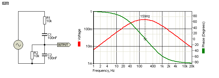
Frequency is determined by the resistance and capacitance, and they are normally all equal - i.e. R1 = R2 and C1 = C2. The standard formula applies ...
f = 1 / ( 2π × R × C ) Where R is resistance in Ohms, and C is capacitance in Farads
When the Wien bridge is combined in a feedback circuit the Q is greatly improved and insertion loss is no longer a problem. Provided the circuit gain is below 3 it won't suddenly become an oscillator, and in the circuit shown below it will provide ±9dB of boost and cut, controlled by the pot.
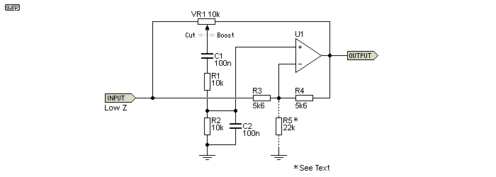
This is all well and good, but to be useful, we need to be able to change the frequency. This is done by using a dual-gang pot so that both resistive sections of the bridge can be varied. Frequency can be adjusted over a 1 decade range (just over 3 octaves), although for an equaliser some may prefer to restrict the range to somewhat less.
About the ideal and simplest approach is to use a 100k pot with a 10k series resistor. The variable resistance is from 10k to 110k, so the frequency range of the circuit will be from (say) 30Hz to 340Hz using 47nF capacitors. To reduce the minimum frequency use larger capacitors, and vice versa. 100nF gives a range from 14Hz to 159Hz.
The 'standard' 11:1 ratio is normally what's expected, allowing (for example) a range from 26-280Hz. The next equaliser might have a range from 140Hz to 1.6kHz, with another from 1.4kHz to 16kHz. It's common for parametric equalisers to have overlapping ranges, but that can be dangerous if two bands are set for the same frequency because the amount of boost available can become excessive.
As shown, the boost and cut are both limited to 9.5dB (times 3 or divided by 3). While this may be considered a bit on the low side, it should be remembered that radical boost and cut aren't often needed, and are generally undesirable. If the parametric filters are also aided by conventional tone controls, the total control range is usually more than sufficient for most purposes. The filters described here are not intended to correct gross flaws, but to allow a wide range of tonal correction to suit the listener, mixing engineer or player.
If you need more boost and cut (and a slightly higher Q), make C1 double the value of C2 (or add R5 - see below for more). Doubling C1 means that the frequency will also change, and the formula becomes ...
f = 0.717 / ( 2π × R × C )
For example, if C1 is 200nF, C2 is 100nF and the resistance (R1 & R2) is 10k, the frequency is reduced to 114Hz (159Hz if both caps are equal). There doesn't appear to be a sensible formula to calculate the proper values when the caps don't follow a 2:1 ratio, but it's easy enough to simulate or test the results. Using 200nF and 100nF will increase the maximum cut and boost to 14dB, and Q is raised to 1.33 (up from 0.88). A similar effect can be obtained by increasing the opamp's gain (reduce R3 or increase R4). That approach is less convenient (to the point of being unusable) because it changes the overall gain even when no cut or boost is applied, and offsets the boost/cut pot's centre position so it's no longer symmetrical.
However, there's a much better way - simply add an extra resistor (R5 in Figure 2, R6 in Figure 3). This increases the gain of the opamp and hence the filter Q, but doesn't cause any ill effects. However, be warned that if you make the value such that the opamp has too much gain you have an oscillator. Using 22k as shown gives ±12dB of boost and cut. The minimum value I suggest is 10k, which will provide almost 17dB boost and cut, which is generally considered excessive. 15k gives just under 14dB boost and cut. As the value of R5 approaches the values of R3 and R4 (Fig. 2 circuit), the amount of boost and cut (and Q) are increased until the circuit oscillates. This occurs once the opamp's gain is three or more.
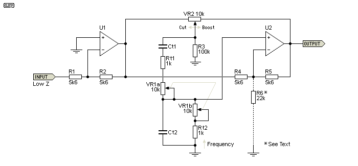
The full (minimised) circuit for a single band is shown above. Because the circuit is inverting, we need an inverting buffer to drive it. This ensures that there is no phase reversal, but of course if you used two circuits, then the buffer must be non-inverting. The input of the equaliser must be driven from a low impedance source or the cut/boost control will be asymmetrical. The frequency control pot is a dual gang type, and both pots are linear. R5 is shown only because it's used in the next circuit, and it can be omitted in this version. Rt and Ct are the timing components (along with VR1a/b.
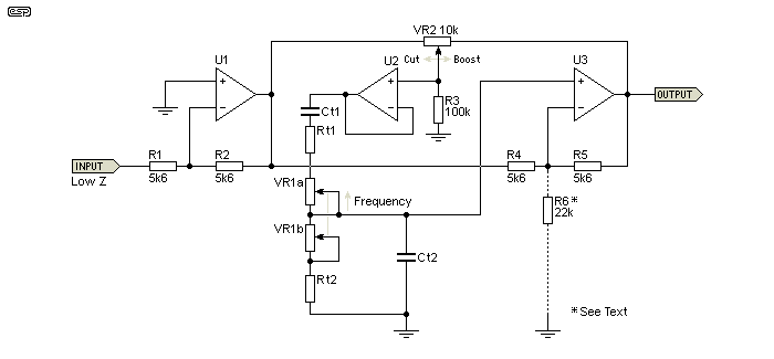
Adding a buffer (U2) improves performance but is not essential, especially for a tone control. The buffer between the boost/cut pot wiper and the Wien bridge minimises interaction between the boost/ cut pot and the Wien bridge. The interaction is a small frequency shift as the boost or cut pot is adjusted (this changes the resistance, and slightly alters the frequency). It also decreases the bridge feed impedance. It is needed if the bridge resistance values are kept low for minimum noise, but it's unlikely that there will be any audible difference that can't be corrected by the controls. R3 is included to prevent large transients if VR2 happens to go open-circuit momentarily, but it does not affect operation.
R6 is optional, and 22k as shown increases the maximum boost and cut to ±12dB. This is a better way to increase the response than changing capacitor values, as the frequency is not affected and the circuit can be considered more 'sensible'.
If the buffer is not included (as shown in Figure 2), all resistance values can be increased by a factor of 5 to 10, and capacitors reduced likewise. This reduces the interaction as boost and cut levels are varied. There will also be a small variation of maximum boost/ cut as the frequency pot is varied. This will happen even with the higher resistor/ pot values, and the only way to prevent it is to include the buffer stage. Without the buffer and with the values shown in Figure 4, there's a frequency shift of around 15% as the boost/ cut control is varied. If the Wien bridge values are set to 10 times those shown (capacitors 1/10), the frequency shift is reduced to less than 4%.
Yet another option is to give the buffer (U2) a small amount of gain, and you can increase the Q and the amount of boost and cut without messing around with the capacitor values. The allowable gain is very small - typically no more than 1.2 and preferably closer to 1.1 (0.83dB). With a buffer gain of 1.1 (10k feedback, 100k to earth) maximum boost and cut is increased to 11.5dB. Excess gain will cause the circuit to become unstable (an oscillator). This is irksome, and it's far better to add the extra resistor to the final stage as described above. Using a buffer with gain is not recommended.
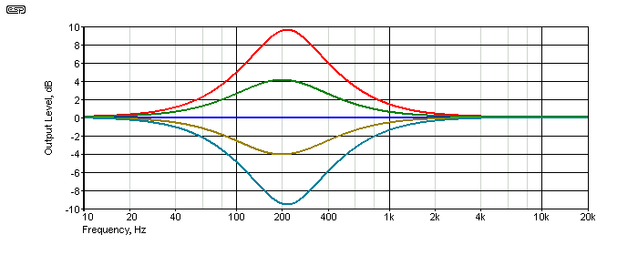
The above graph shows the response at ±50% and ±100% boost and cut, as well as with the pot centred. This graph is without the buffer, and the small frequency shift is just visible if you look carefully. C1 and C2 were 68nF, and the frequency pot was set for maximum resistance (minimum frequency). I also built the circuit so I could listen to it, and it performs exactly as expected. In addition, I tested the 'high-Q' version (different cap values and buffer with gain), and while they certainly work as described, the amount of boost/ cut is probably a bit extreme. The higher Q is also very audible in boost mode.
The response with the optional resistor (R8) is pretty much identical to the above, except that the boost and cut are increased to 12dB rather than the default 9dB. You may wonder why adding R8 makes a difference, because the -ve input to the opamp (U2) appears to be a 'virtual earth'. However, it's not, because the opamp has two signal inputs - the +ve input has the output signal from the Wien bridge, and that's the one that is amplified by two (without R8) or by more than two when R8 is fitted. When VR2 is centred though, there is zero output from the bridge and R8 does nothing at all. Fear not, you don't need to understand the finer points to get it to work.
If the resistor and pot values are as shown above, it's helpful to know what component values are needed for each frequency range. There are many possibilities, but not all are useful because they are too close to other frequency bands, or below or above the frequencies of interest. The following table shows the frequencies you can get from readily available capacitor values.
All caps are included, but you may find that some capacitor values are not easily obtained. We normally expect that cap values will follow the E12 series, and that provides frequencies as follows ...
| 10 | 12 | 15 | 18 | 22 | 27 | 33 | 39 | 47 | 56 | 68 | 82 | 100 | nF | |
| Min | 1.45k | 1.21k | 964 | 804 | 657 | 536 | 438 | 371 | 308 | 258 | 213 | 176 | 145 | Hz |
| Max | 15.9k | 13.3k | 10.6k | 8.84k | 7.23k | 5.89k | 4.82k | 4.08k | 3.39k | 2.84k | 2.34k | 1.94k | 1.59k | Hz |
Higher and lower ranges are obtained by multiplying or dividing the cap values and frequencies by 10 as needed. If the cap value is multiplied by 10, the frequency is divided by 10 and vice versa. For example, using 220nF caps gives a range from 65.7Hz to 723Hz. For frequencies below 50Hz or so, you may prefer to increase the resistor and pot values - you can use 2.2k resistors and 20k tuning pots - don't change VR2, it should remain as 10k. As noted above, the frequency is determined by ...
f = 1 / ( 2π × R × C ) Where R is resistance in ohms, and C is capacitance in Farads
Using the formula, you can determine the frequency for any tuning pot setting, and remember to add the resistor in series with each pot section.
Be aware that some suppliers have decided to 'economise' by restricting the available range of capacitors. For example, 82nF seems to be a value that some suppliers have decided people don't need (they are quite wrong of course). Not all values will be available in a particular case style, so you need to check that you can get the required values in your preferred case type (for example MKT 'box' style).
The table below assumes a linear pot. Ideally, you'd use an antilog pot but unless the taper is really a reverse logarithmic type (very rare and generally considered unobtainable), you are better off with the linear taper. Although it gets a little touchy as you get close to minimum resistance (maximum frequency), linear pots generally have better tracking than log or reverse log, and are far more predictable.
| Rotation | 0 | 10 | 20 | 30 | 40 | 50 | 60 | 70 | 80 | 90 | 100% |
| Frequency | 0.91 | 1.00 | 1.11 | 1.25 | 1.43 | 1.67 | 2.00 | 2.50 | 3.34 | 5.00 | 10.0 |
Note that 0% rotation means the pot is at maximum resistance and therefore minimum frequency. The range is a little over one decade (11:1), but it can be limited if you prefer by increasing the value of the resistor in series with the pot. For example, if you use 2.7k series resistors with 10k pots, the range is reduced to a little under 5:1 which may be preferred in some cases. Changing the resistors alters both the upper and lower frequency, and you'll need to calculate the frequencies using the formula shown above.
The circuits shown above have a typical Q of 0.88 or 1.33, but that may be considered too low. For an octave band graphic equaliser, the Q is 1.414, but the version shown next has a Q of 2, but it's still not a constant-Q design. It uses the same number of opamps, resistors and capacitors, and may be considered a 'better' circuit. The maximum boost and cut is increased to 16dB. Like the other versions, the circuit will oscillate if the gain of U2 is increased beyond three. It's possible to get the Q higher than 2, but it's not recommended.
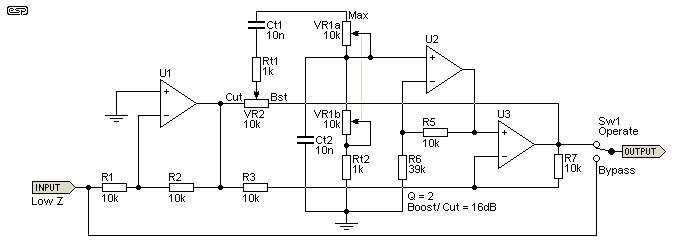
With the increased Q, you get a bit more control, but it can't reach the same limits that you get with a state-variable filter. It does use far fewer opamps though. A state-variable parametric will use five opamp sections for each filter, and a a result it's far more flexible. You need to ask yourself if you really need that flexibility, or if it would just be 'nice'.
I added a bypass function to this diagram, which eliminates the circuit noise of a section that's not being used. This can be included with the other versions as well, and is particularly useful if you build a 4-way equaliser, but only end up using (say) one or two. There's no reason to add noise that can easily be removed. How much noise? That depends on the opamps you use. Remember that this type of EQ is normally used at fairly high levels (around 0dBV), and even at maximum boost with a 1V input, the output level 'only' goes up to 6.2V RMS (under 9V peak).
While I've shown the resistor values as 10k (rather than 5.6k as used in other examples). Likewise, you can change the other circuits to use 10k as well, but remember that the buffer's 'gain boost' resistor (R6 in most circuits) must also be changed.
This is an easily tuned equaliser, and has the advantage that the Q doesn't change as the frequency is varied. It's not as flexible as a state-variable approach, but is far more economical, needing only one opamp for each section. Three of these along with traditional Baxandall bass and treble controls makes a very flexible equaliser that would be ideally suited to general-purpose EQ tasks, but is especially suited to bass guitar and other instrument EQ.
Noise is unlikely to be a problem provided low-noise opamps are used. The resistor values shown are deliberately somewhat lower than you might expect to ensure that thermal noise is minimised. The values are not critical though, and you can use higher value pots if you wish to use smaller value capacitors. I recommend NE5532 or OPA2134 dual opamps for this project, but you can use others that you may prefer (for example, the LM4562 is a particularly good part, but they are rather expensive). Note that if your favourite opamp is unable to drive low impedance loads, you may need to scale all resistances up by a factor of 2-10. Capacitors must then be scaled down by a factor of 2-10. So, 5.6k might become 10k and 100nF changed to 47nF (for example). Pots should also be 2-10 times greater value than shown.
The finer points of the circuit operation are fairly complex, but it's not necessary to understand its deep inner workings to be able to build an effective equaliser. Without getting into complex maths, it's not easy to understand (and many people won't be able to follow the maths anyway). All will hopefully become clear when you build it and experiment a little. For those who use a simulator, I recommend you use it, as it's possible to take virtual measurements that are otherwise difficult or impossible.
A follow-up article is available (See Project 152-1) that covers what could be described as the 'ultimate' bass preamp. The general arrangement is as described above - 3 parametric EQ sections plus bass & treble, along with the other functions that are needed by bass players.
1 EDN edn.com Wien-Bridge Filters Enhance Tone Control, EDN Magazine (Frederic Boes, Belgium)
2 US Patent US3729687 - System for selective frequency amplification or attenuation
 Main Index
 Projects Index