
|
|
| Elliott Sound Products | Dimmers And LEDs |
 Main Index
Lamps & Energy Index
Main Index
Lamps & Energy Index
Contents
Dimming LEDs is easy, right? Well, the correct answer is yes and no. LEDs are one of the easiest to dim of all the technologies we have ever used for lighting, yet there are seemingly insurmountable problems. The problem is that almost no-one is willing to accept that existing 2-wire dimmers (whether leading or trailing edge) are simply not suited for LED dimming.
In fact, these standard dimmers aren't suitable for any electronic lighting load, including 'dimmable' compact fluorescent lamps. They were designed to be used with incandescent lamps, and these are the only loads that will behave predictably with conventional dimmers.
If you haven't done so already, please read Lighting Dimmers (Part I and Part II), as those articles describe the circuitry used, and some of the problems faced. The following is reproduced from 'Lighting Dimmers (Part I)', because it is fundamental to the issues faced ...
Almost all domestic dimmers are 2-wire, and therefore have no neutral connection. This places many constraints on the dimmer and how well (or otherwise) it will work, especially with non-resistive loads. These standard series-wired dimmers work fine with incandescent lamps, because the lamp filament provides a continuous connection to neutral and the dimmer has a reference (at least of sorts). With electronic power supplies (CFLs, LEDs, etc.), this reference is not present until the lamp starts to draw current, and dimmer operation may be erratic at best or useless at worst. One way this can be 'fixed' is to use an incandescent lamp in parallel with the electronic lamp. A single (small) incandescent lamp can be used with multiple electronic lamps - provided of course that they are specifically intended for use with dimmers!
The crucial issue is the lack of a neutral connection with electronic loads. This means that there is no return circuit path until such time as the electronic load starts to pass current. The dimmer therefore has no reference, so the dimmer circuitry has to reset itself 100 or 120 times every second. Dimmable lamp manufacturers have tried many different ways to try to ensure that the dimmer doesn't lose its essential reference. Some work well enough, others not so well.
It is important to understand that the standard 2-wire dimmer was designed to be used with incandescent lamps. Despite anything you will read elsewhere, operation will be unpredictable with ANY load that is not an incandescent lamp! For reliable performance with electronic loads (dimmable LED or CFL lamps), the dimmer should be 3-wire (active, neutral and load). Unfortunately, these are uncommon and will usually be difficult to install as a retro-fit because most lighting switch boxes don't have the neutral available. 2-wire dimmers were designed for incandescent (resistive) lamps, and were never intended for use with electronic load.
Most 'dimmable' LED lamps use specialised ICs (integrated circuits) that are designed to function with the chopped waveform from the dimmer. One technique is to utilise circuitry that calculates the on/off ratio, and adjusts the current to the LEDs accordingly. This is not especially hard to do with modern ICs, but it invariably results in the light level being somewhat unstable at very low settings.
Some dimmers may become confused if there is another signal superimposed on the mains 50/60Hz waveform. Some sources of these extraneous signals include 'control tones' (aka ripple control), used to switch off-peak appliances (such as storage hot water systems or under-floor heating), transient signals created by other appliances being turned on or off (especially induction motors) or anything else that creates mains interference. Because dimmers are often used at low settings because of the high efficiency of LEDs, they are operating at or near their most unstable setting.
Even a small variation of the mains voltage can cause a very noticeable change of light level. It is inevitable that the mains voltage will vary. Although the power utility may state that your mains voltage is 230V or 120V, that's simply the nominal value - it can vary by ±10% or more. There will be periods of the day when the voltage is very unstable - especially during the peak periods when hundreds of people in your area are preparing meals, and the load varies as major appliances (stoves, air-conditioners, etc.) are turned on and off.
Despite every indication that they are unsuitable, many lighting manufacturers still insist that their products are dimmable with either leading or trailing edge dimmers. In a simple test that I ran using 8 x 11W downlights, the peak current with a leading edge dimmer was over 12 amps! This peak is very short duration, but is liable to damage the dimmer as well as the lights themselves. The current waveform is shown below. See Lighting Dimmers if you don't understand the difference between leading and trailing edge dimmers. The current monitor sets the oscilloscope scale to 1/10th of the reading shown, so 1.6V RMS is 160mA.
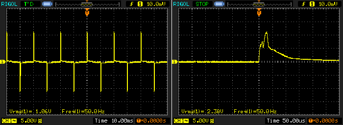
Figure 1 - Peak Current With Leading-Edge Dimmer
The image on the left shows the complete waveform, and the right image shows the peak in detail. Only the positive peak is shown - the negative peak is identical. Although the RMS current is only 106mA, the peak current is almost 12A and this causes stress to the dimmer and the lamp. Somewhat surprisingly, the peak current is not reduced by very much if the number of lamps is reduced. This is because the circuit resistance (roof wiring, switch, dimmer, and all wiring right back to the generating station) limits the maximum value that can be obtained. In this case, the local wiring and internal resistance of the dimmer becomes the main limiting factor.
Do Not Use Leading Edge Dimmers With LEDs or CFLs ... Or Any Electronic Load
The exact same group of downlights (but using four this time) was tested with a trailing-edge dimmer. The peak current did not exceed 280mA, with an RMS current of 170mA (the oscilloscope scale is x1 for this test, so 42mV is 42mA). The waveform shown below is typical of what you might expect. The dimmer is set for about the minimum useable level and 50% rotation of the knob does not equate to half the light with the vast majority of LED lamps.
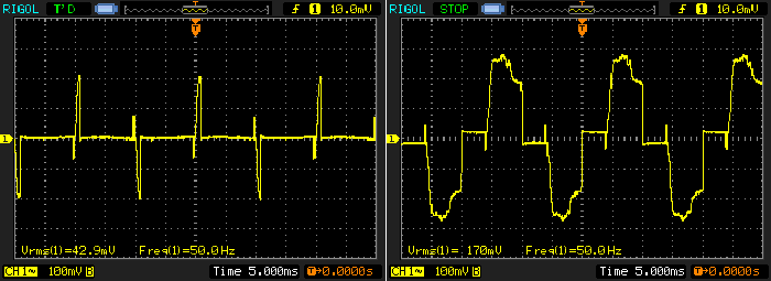
Figure 2 - Peak Current With trailing-Edge Dimmer
There is no setting with a trailing-edge (or universal) dimmer that causes a peak current of more than 280mA (with 4 lamps as tested). The image on the left shows the waveform when the dimmer is set to the lowest usable setting, and the one on the right is with the dimmer at maximum. With fewer lamps, the current is reduced in direct proportion and vice versa. However, the dimming performance is still somewhat unpredictable, regardless of the number of lamps. In particular, very low light levels are unstable. Even a small change of the incoming mains voltage can cause a disproportionate change of the light level. Not surprisingly, people find this to be disconcerting and definitely not what they are used to seeing.
There are good reasons for this, but they don't appear to be well understood ...
To dim a traditional filament (incandescent) lamp, any reduction of RMS voltage causes a reduction of light output. An incandescent lamp doesn't care if the waveform is a sinewave or the chopped waveform from a dimmer - it responds only to the RMS voltage. However, the process is not linear, and reducing the voltage to half cause the light level to fall much further (I measured the light output at less than 10% in a test that was done for this article). It is the very non-linearity of an incandescent lamp that makes its dimming performance seem so good. In addition, as the light level is reduced, the colour temperature is also reduced. A normal GLS (general lighting service) incandescent lamp has a colour temperature at full brightness of around 2,700K, and this falls as the voltage is reduced. This is what creates the nice warm glow of dimmed incandescent lamps.
Unfortunately, the non-linearity also means that power savings are not proportional to light output. You might expect that with half the light, you'd also be using half the power, but this isn't the case at all. In fact, at 1/2 light output, the power input will only have fallen by around 25%, but it might be less depending on the lamp itself. Although not generally acknowledged, this non-linearity is extremely useful because it avoids the instability that will always occur at very low settings. The following table shows the data measured from a 75W incandescent lamp ...
| Voltage | Lux | Power | Comments |
| 230 V | 17,350 | 79.9 W | Full brightness |
| 220 V | 15,000 | 73.8 W | |
| 210 V | 12,380 | 68.6 W | |
| 200 V | 10,000 | 63.3 W | |
| 190 V | 8,390 | 58.7 W | Just under ½ brightness |
| 180 V | 6,630 | 53.7 W | |
| 170 V | 5,140 | 48.9 W | |
| 160 V | 4,020 | 44.7 W | Just under ¼ brightness |
| 150 V | 2,940 | 40.2 W | |
| 140 V | 2,070 | 35.5 W | |
| 130 V | 1,490 | 32.2 W | |
| 120 V | 1,030 | 28.7 W | |
| 100 V | 670 | 25.2 W | |
| 90 V | 370 | 21.3 W | Lowest useful setting |
| 80 V | 102 | 15.8 W | |
| 70 V | 48 | 12.7 W | |
| 60 V | 17 | 10.2 W | Very dull red |
| 50 V | 4.8 | 7.9 W | |
| 40 V | 0.8 | 5.8 W |
As noted above, the inherent non-linearity of an incandescent lamp is exactly what we need for comfortable lighting. The dimmer is working with sensible voltages at all but the very lowest settings. These are not very useful because the light output is far too low. At nearly all settings that are within the useful range, the dimmer will not be overly affected by mains variations. Even so, many readers will be aware that even incandescent lamps may show some instability when dimmed, but the non-linearity of the lamp itself is such that it was never very noticeable.
LEDs do not have this non-linearity, and the light output is (almost) directly proportional to the LED current. This means that if you need low light levels, the dimmer will be set for unrealistically low output - in fact right where the dimmer itself is most unstable. The smallest mains voltage disturbance may cause the dimmer to vary its output, and because the LEDs are operating at low current and a fairly low light level, our eyes are very sensitive to any variation.
There have been quite a few attempts at making LED power supplies (ballasts) respond to the waveform from a phase cut dimmer. It is only possible because major IC manufacturers have realised that dimming is important to a great many people, and that very few people are willing to have additional wiring installed just to make their new LED 'bulbs' dimmable. There are Wi-Fi solutions, but these are expensive and most people don't want to have to use their computer, tablet or mobile phone to control their lighting.
The wall-plate dimmer is a very simple, robust and useable control mechanism. It's relatively low cost, and can easily be retro-fitted to replace a simple on/off switch. No-one, from the youngest to the oldest, has any problems with the concept of turning a knob to make the lights brighter or dimmer. The problems started when various governments started to ban incandescent lamps, either directly or by stealth. 'Dimmable' compact fluorescent lamps (CFLs) don't dim very well at all, and without exception must not be used with leading-edge dimmers.
When LEDs started to become both popular and affordable, it was assumed that dimming would no longer be an issue. After all, LEDs have an infinitely variable light output, from zero up to their maximum. What wasn't considered was just how an electronic power supply could offer the necessary high efficiency, yet still be dimmable using existing dimmers. There have been several attempts and as many different 'solutions' as there are LED lamp manufacturers. Some do work very well, but all that I've seen have the problem discussed above - they are unstable at very low light settings.
The essential parts of a phase-cut dimmable driver are shown below. The power supply section must be able to operate from very low voltages, and most importantly it should act like a resistive load over as much of the mains waveform as possible. This is usually achieved by using active power factor correction circuitry. Even though the power factor of a lamp dimmed using a leading or trailing edge dimmer is woeful, the active power factor correction circuit is the only way to make the load appear resistive [1 & 2].
The controller IC provides the necessary logic to control the current through the LEDs, but also measures the 'off' period when the dimmer is not providing power. For 50Hz mains, the maximum off period is 10ms for each half cycle - no power at all. The minimum off period is of course (virtually) zero, meaning that power is applied all the time (for 60Hz mains, the maximum off period is 8.33ms). The controller IC uses the off time as a control signal, reducing the current to the LEDs.
Figure 3 - Conceptual 'Phase-Cut' Dimmable LED Driver [2]
In the above example schematic (based on the Fairchild typical application circuit), the 'DIM' terminal is used to determine the nature of the mains waveform. From this, the LED current is calculated internally to match the 'off-time' of the mains waveform. The IC itself is quite complex as might be expected - there are a lot of different tasks that the IC must control.
The above is only one example, but most of the ICs from other manufacturers are fairly similar in what they do. The internals are usually very different, but the same outcome is desired. Unfortunately, what we have at present is not subject to any standards or rules, so a 'dimmable' LED lamp from any supplier may only work with a relatively small number of dimmers.
Even where the overall performance seems to be very good, at very low light levels you can expect almost all combinations to be somewhat unstable. Some lamps with some dimmers will be unusable, but you won't know that until you actually try the combination.
This has proven itself to be a most vexing question, and has prompted several articles, white papers and other material from all manner of different organisations. LED makers, government agencies and private individuals have all had their say. One of the better articles that I've found is from the US Department of Energy, and is entitled "What You Need to Know about LED Flicker and Dimming" [3]. The picture is rather bleak for anyone who thinks that LEDs can simply be substituted for incandescent lamps and everything will work just like it always did.
In most cases, the response is "No it won't!". You might get lucky and end up with a compatible combination on your first try, but the chances are that this won't be the case. I've experimented with many different lamps and dimmers, and even dimmers that are the same type (for example trailing-edge) can behave quite differently from each other. Some may be virtually useless unless there's a single incandescent lamp installed on the same circuit as the LED lights, while others will seem to be fine.
The problems really start when the customer wants to run the lights are very low levels. As noted above, there is a very strong likelihood that many lamp/ dimmer combinations will be unstable. Not all the time and probably quite rarely, but still often enough that it becomes a real nuisance. This annoys customers and suppliers alike - customers because they don't get what they expected, and suppliers because at the times they check the lamps, dimmers and wiring, there appears to be no problem.
As noted above, finding a dimmer and lamp combination that performs the way you want isn't easy. Despite my dire warnings (which are still valid), some lamps may only function 'normally' with a leading edge (TRIAC) dimmer, which causes a conundrum. Leading edge dimmers create very high peak current as the TRIAC switches on, so while the combination of light and dimmer works properly in terms of dimming, either the lamp(s) or dimmer may fail prematurely.
Of course, you might be lucky and have enough wiring resistance between the dimmer and the lamps that the current is tamed to an acceptable value. It's safe to say that no installers or householders have the equipment or the expertise to measure the peak current. It requires laboratory equipment that even many manufacturers don't have, so almost everyone else is oblivious to the possible risk. While the chance of fire is certainly possible, it is (hopefully) rather unlikely. The problem is that few manufacturers will run tests to destruction, so no-one really knows what will fail and how it fails.
Still one of the biggest problems though is low-level dimming. As noted above, LEDs are comparatively linear, and light output is directly proportional to the current through the LED(s). Dimming an incandescent lamp to 1% of maximum light output is fairly easy, although even then people have found that (especially cheap) TRIAC dimmers may show some instability.
With LEDs, dimming to 1% is not so easy, because the current will be literally 1/100th of that needed for full brightness. Standard LED dimming techniques are not stable at such a low current, and nor are most dimmers. This instability can cause the lamps to flicker (rapidly varying light level), flash (on/off) or go out altogether, simply because of a small drop in the mains voltage or due to interference from mains control tones or other noise.
Interestingly, I have found during testing that sinewave dimming (which is decidedly obsolete - up until fairly recently) generally works better than phase-cut dimmers (both leading or trailing edge), and also maintains a good power factor at all settings. Making a sinewave dimmer is certainly possible, but having a similar form-factor (size and shape) to existing phase-cut dimmers is more difficult. Sinewave dimming also requires a high level of integration (relatively complex ICs) and fairly large passive components. For this to happen, manufacturers have to actually step up to the challenge. This is already happening, although the complexity of the systems means that household use is not yet mainstream.
The use of sinewave dimmers dates back to the earliest theatre systems, where a large power resistor or even electrodes in a container of salt water were used to vary the lamp power. Later, variable autotransformers (e.g. Variac ™) were used, and these are far more power-efficient, having extremely low loss at any output voltage. Sinewave dimming was displaced in almost all cases with thyristors (SCRs or TRIACs), which are extremely efficient, but create a terrible power factor back to the power utility. Now, of course, they are causing major headaches with LED lighting because making a LED power supply that's compatible with all dimmers is well-nigh impossible.
Mains distortion is now being monitored, and new products have to comply with regulations that will effectively eliminate all forms of phase-cut dimmers (leading and trailing edge). While these regulations may not come into effect immediately, it's only a matter of time before phase-cut dimmers are part of history.
For detailed explanations of the various dimmer types, see Light Dimmers - there is no point repeating everything here.
One of the oldest dimming protocols has a new lease on life with LED luminaires - i.e. complete fittings, such as ceiling lights, highbay fittings and many others. 0-10V dimming was first used in theatre and event lighting, providing a simple protocol that controls the lamp brightness from a remote location, and without the need for mains wiring to the dimmer.
It's important to understand that while the protocol is the same as that used for old lighting desks (for theatres and other venues), the functionality is very different within the LED power supply/ ballast. Rather than using 'phase cut' dimmers, the 1-10V signal controls the current delivered to the LEDs inside the power supply itself, resulting in higher overall efficiency and a high power factor over the full range. Although the original 0-10V terminology has been retained, the majority of ballasts are actually controlled over the range of 1-10V, where 1V or less is either off, or minimum brightness (typically 10%).
It's taken far too long (IMO), but relatively recent changes to the IEC60929 (Annex E - (normative) Control interface for controllable control gear) Technical Standard now include requirements for 0-10V dimming. The 'dimming controller' referred to is the dimmer unit itself, which is installed so users can adjust the light level. The important parts of the standard state ...
- Minimum sinking current to the dimming controller is 10µA and maximum sinking current is 2 mA.
- Under no circumstances should the interface circuit terminals to the dimming controller produce a voltage exceeding ±20V.
- The driver/ballast should not be damaged when dimming voltage is between ±20V.
- The control terminals of the interface circuit shall be reverse polarity protected. In the case of reverse polarity of the interface control terminals, output light should be at minimum or turned off.
- The dimming circuit interface should produce stable output light for a dimming control voltage between 0-11V.
- When the signal of the dimming controller is 10V or higher, output light should be at maximum. When the signal of the dimming controller is 1V or lower, output light should be at minimum or off.
- If no dimming controller is used, the dimming terminals are usually kept open and output light should be at maximum. If the dimming terminals are shorted together, output light should be at minimum.
- The supply wire of the dimming terminal is purple/ violet and the return is grey.
- Double or reinforced insulation/ isolation from all hazardous voltages including the input voltage is required for safety in all cases where the dimming controller circuitry is user-accessible.
There are already many fittings and power supplies ('ballasts') that comply either in part or in full, and having the interface standardised means that suppliers, installers and end users know what to expect. this ensures that (hopefully) there will be no issues with an installation - even if luminaires are subsequently replaced with others from a different manufacturer. Note that the dimming connections (purple (+ve) and grey (-ve)) are expected to be fully isolated if the dimmer is accessible, but those I've seen so far are isolated regardless. Isolation can improve dimming performance by keeping high frequency switching noise away from the dimming signals, and is normally provided whether the dimmer is 'user accessible' or not.
The specifications and recommendations help to provide a degree of confidence to everyone in the supply chain. Rather than convoluted (and almost always incompatible) digital dimming schemes, the use of a simple solution is really an all-win. While digital control is generally considered to be 'better' (or at least more 'high tech'), it's like using a sledgehammer to kill a flea - totally unnecessary and vastly over-complicated for a very simple task. Any equipment (including digital controllers) can produce a 0-10V control voltage for dimming, and in simple (non-automated) applications there is no requirement for expensive peripherals and the inevitable interoperability problems that occur with complex control systems.
This is one of the best pieces of news I've come across lately, and while I've already seen many products using 0-10V dimming, there were a few that didn't follow any real pattern. They worked with 0-10V, but some needed a third wire (10V) and didn't follow the standard as shown above. Of course, others did follow the standard (or close to it).
In many cases, the dimmer will be very simple, but its performance may change depending on the number of fixtures connected. Some dimmers will have an inbuilt 10V or 12V power supply rather than relying on the 0-10V current drawn from the fixture's power supply. This allows for a remote 3-wire dimming controller that will provide consistent performance. As noted above, the sink current (i.e. the current that must be pulled from the power supply/ ballast) can range from 2mA down to 10µA (a variation of 200:1), so a simple passive dimmer with no inbuilt power supply may struggle to keep the dimming voltage constant with varying numbers of fixtures attached.
Power supplies that offer 0-10V dimming provide a small current at a positive voltage (10V open circuit) via the violet (control) wire. The current available is limited to a maximum of 2mA according to the standard, but it may be a little higher in some cases. When the external dimming controller draws current from the control lead to the return lead (grey), the voltage is reduced and the power supply/ ballast reacts to the reduced voltage by reducing the current supplied to the LEDs. This is usually done using PWM (pulse width modulation). Drawing current from the power supply is known as 'sinking' current, while the power supply itself is the source.
It's dead easy to sink anywhere between 10µA up to 1A or more consistently (regardless of actual current) when the dimmer has its own power supply, but it's a lot harder if the dimmer has to rely on the ballast's small output current to provide its only source of voltage and current. When the exact current is known, a simple variable resistance is all that you need, but the current will vary depending on the number of fixtures used, so the dimmer becomes more complex and less predictable. When a separate fixed voltage supply is available for the dimming controller the number of connected lamps no longer matters. The dimmer control shown in the next section does work quite well though.
This is no doubt something that will be worked out over time, and it should be possible to get some additional standardisation for what is now one of the most common requirements. Dimming is no longer seen as a 'luxury' - it's become a major part of industrial and commercial lighting. One of the biggest drivers for this is the cost of electricity, and the savings that can be made if lighting provides the light level needed, rather than just being on or off. So-called 'daylight harvesting', where lighting is adjusted depending on the amount of daylight available has become a driving force, and it's readily apparent to all concerned that simple analogue solutions are easier, cheaper and more easily adapted than digital methods.
It may come to pass that a 'universal' digital standard emerges so there are no compatibility issues between different manufacturers, but until that happens, 0-10V is the preferred option and is a low cost but very effective control system that won't go away any time soon. Automation (e.g. CBUS, DALI) systems have always been able to be fitted with 0-10V interfaces, and they will no doubt become ever more popular as more fittings use that standard.
Given that 0-10V dimming is now quite popular and is being used in many installations, one would have hoped that schematics for simple controllers would be easy to find. Unfortunately (and not for the first time) this is not the case. Not only are circuit diagrams for the controllers themselves absent from the Web, but even the physical controllers are not easy to find. In some cases you will find what you're looking for, but I've seen what appear to be exceptionally simple controllers on-line for well over AU$100, which is far, far greater than their value. Meanwhile, others (which appear to do exactly the same thing) sell for not much over AU$17 or so. The sellers provide next to no information about how they are to be used, so it's hard for people to know what they are getting.
Figure 4 - Tested Controller Circuit For 0-10V Dimmable Drivers
The circuit shown above is a simple passive (it needs no power supply) controller, which will work with any LED power supply that provides more than 200µA for the dimmer. It will function with lower current, but the dimming range becomes rather non-linear. This isn't a precision circuit, and it may be more or less complex than commercial versions. I don't know how complex (or simple) they are, since I don't have any to experiment with.
The transistor pair acts as a high gain emitter-follower, controlled by the variable resistor (a 1Meg linear potentiometer). The resistor is used to help get a slightly more linear range. The capacitor helps reduce noise and zener diode protects the circuit against higher than normal voltage or reverse polarity. Naturally, this circuit can only be used with 10V current limited DC, and it will fail instantly if used with mains voltage.
The circuit shown (the Dimmer Controller) has been tested with a dimmable driver, and it functions exactly as it should. With the values shown, the minimum voltage (control fully anti-clockwise) is about 0.7V, and this is perfectly fine for most supplies (which are really 1-10V rather than 0-10V). The 1V level is either 10% brightness of off, depending on the driver itself. In some cases, it may be a user-selectable option.
Figure 5 - 0-10V Controller Circuit Vs Number Of Luminaires
The above shows the variation of control voltage with different numbers of luminaires. Each trace should be a straight line at the same level as the pot rotation, so 50% should give 5V. Because the circuit has no independent power supply, it's not that accurate, but it's more than good enough for dimming. People set dimmers to a particular light level, not by looking at the knob's position.
The dimmer controller would normally be mounted on a standard wall-plate, along with the on/off switch for the controlled lights. Note that a separate wiring run is needed for the 0-10V dimming connections, but this 'daisy chains' from one fitting to the next. The maximum current for the controller shown is around 25mA (half the maximum current shown above), and Q2 will run warm at that current. There should be no more than 25 separate fittings connected to a single dimmer controller, or the number of fittings that amount to 25mA current, whichever is the lower number. For example, if the LED drivers output 2mA (the maximum recommended), then no more than 12 fittings should be on a single dimmer circuit.
At the time of writing, this is the only schematic on the Net for a passive 0-10V current-sinking dimmer controller. It may or may not follow industry practice, but it works very well. It's been tested with a dimmable LED highbay, the only 0-10V dimmable fitting I had to hand when the circuit was developed. I expect that it will perform equivalently with any standardised equipment. While it does work at the lowest current suggested in the standard (10µA), it really needs at least 100µA to function properly. (It is doubtful that many commercial products would use a 10µA sense current because it's too low, the overall impedance is too high and noise may become a problem.)
If you want to get good dimming from LED lights, you have an uphill battle unless you use fixtures rather than replaceable 'bulbs'. An arrangement that works flawlessly in the workshop may be quite unstable in the customer's premises. The reason can be anyone's guess - we simply don't know of all the possible interactions that occur in an installation, and they are virtually impossible to predict in advance.
Until such time as sinewave dimmers (which must be 3-wire - active, load and neutral) become more readily available in a form factor that suits existing wall plates, dimming will continue to cause problems for lighting manufacturers, suppliers and customers. Most people are reluctant (to put it mildly) to have new wiring installed to suit other dimming protocols such as 0-10V, C-Bus or DALI. All of these can represent a significant investment, and none is suited to retro-fit 'bulbs' because they do not have any external means of being controlled other than via the mains. This will continue to be a problem until users are willing to make a permanent change.
So, if you want to have dimmable LED lamps, feel free to experiment.
In fact, you must experiment, because the results are almost always unpredictable!
Even when you find a combination that works well, don't expect the same dimming range or stability that you had with incandescent lamps, because you probably won't get it. You might be lucky, but a seemingly infinite number of sites on the Net telling you of the problems encountered doesn't bode well. This really is a case of buyer beware - the lights are usually very good (from reputable manufacturers at least), but dimming is another matter entirely. 0-10V standardisation is very much a step in the right direction, but only for fixed installations.
Ultimately, the best approach (and the one that will endure) is to use complete fixtures/ luminaires and forget the silly idea of replaceable globes. If you need dimming, choose a product that includes a 0-10V interface, but you will have get an electrician to install the extra wiring needed for the dimmer unit itself.
There is (and always will be) one enduring problem of course, and that's the power supply. Almost all LED lighting uses switchmode power supplies, and without exception, they are the least reliable part of the lamp or fixture. There is no way at present to ensure that any power supply will operate for 100,000 hours or more without failure, because there are too many components involved, and the failure of just one part means that the supply no longer works properly (if at all). Manufactures don't deliberately make their supplies so they will fail - it's simply a fact of life.
Heat remains the #1 problem with all lighting that uses an electronic power supply/ ballast, and everyone has to get used to the fact that LED lighting in any configuration (and the power supply if separate) must be kept as cool as possible. Despite all the information available, this is the one thing that appears to cause more failures than anything else. It doesn't help when LED luminaire makers and suppliers often fail to advise installers of the heat issues, so many installations are inappropriate. It's not uncommon for the ceiling space of a dwelling to exceed 50°C, and when that's added to the temperature rise of the fitting itself, problems are a certainty.
Unlike early (simple) solutions such as incandescent or magnetic ballasted fluorescent fittings, electronic power supplies/ ballasts are sensitive to over-voltage. Incandescent lamps will fail much faster if their rated voltage is exceeded, but the replacement cost is small and it's easy for the householder to fit a new one. It's not supposed to happen, but the nominal 230V mains (120V in the US) can easily reach 260V (135V), although according to the standards in place it should not exceed 253V (+10%) in Australia. Some fittings cannot handle the higher than normal voltage, especially if prolonged. The range of problems this can cause varies with the design, but unless the electronics are designed to handle the higher than normal voltage, they will fail prematurely. Many LED power supplies are now rated for a maximum voltage of 277V to account for this, but most of the cheaper ones are not.
Main Index
Lamps & Energy Index