

|
| Elliott Sound Products | Frequency Changer for Low Voltage Synchronous Clocks |
 Main Index Main Index
 Clocks Index Clocks Index
|
The article Old Synchronous Clocks explains how to rewind a synchronous clock for low voltage operation, and this project allows you to run a modified clock at its original frequency. 50Hz synchronous motors normally can't be used with a 60Hz supply because they run 20% fast, and 60Hz clocks run 16.7% slow at 50Hz. While this is often simply ignored, if it is desired to have the clock running and keeping time, the change usually means that the motor's gearing has to be changed. Depending on the clock's construction, the degree of difficulty can range from fairly simple (if you have the tools) to extremely difficult. In a very few instances, it might be possible to obtain a replacement motor, however this will typically only apply for a 60Hz conversion of 50Hz American made motors.
Rather than change the gearing (which is very difficult to reverse if originality is desirable), it's far easier to run the clock at a low voltage, keeping the original coil for posterity. Once the clock is thus converted, it becomes a fairly simple matter to change the frequency, and because no high voltages are involved there is no risk to life or limb. While the necessary electronics and amplifier are simple, they may be beyond the skill-set of many clock enthusiasts, however a friend can always be roped in to assist if needs be.
Where a clock is going to be rewound, it is important to carry out the tests at the intended frequency. This is because motors are frequency dependent - not just for speed, but also for their electrical operating characteristics. A motor designed for 60Hz will draw considerably more current than normal at 50Hz - 20% more in fact. Likewise, a 50Hz motor will draw less than normal current at 60Hz. Without access to mains at the intended frequency, it can be a pain to figure out what to do, however, if you build this project first it all becomes too easy. You not only have the required frequency available, but the voltage can be changed too.
The problem of voltage vs frequency is caused because motors are reactive devices - they have impedance, the AC equivalent of resistance in a DC circuit. As the motor's driving force is derived from the current drawn, as frequency increases, current decreases and vice versa. If the current is reduced because of a higher than normal frequency, the motor may not run - tests performed on the Telechron motor described in the article referenced above showed that with 16V AC applied at 60Hz, the motor flatly refused to run. It was necessary to increase the voltage to just under 20V before the motor would start and run reliably.
 | One thing that you will definitely need for this project is an oscilloscope. Because the signals used are all low frequency, a PC based oscilloscope will be fine, but make sure that your sound card includes a facility for dealing with high-level signals. If not, you will need to use an attenuator - hopefully, sites providing software for oscilloscopes will explain what you need and how to achieve it (try the help file(s), as they often contain useful snippets of information). |
I must point out that the complete project has not (at the time of writing) been built, however the vast majority is so straightforward that I am confident that it will function exactly as described. Each section has been simulated, and the values shown are correct. The zero-crossing detector, Schmitt trigger and first filter have been built according to the theoretical values calculated, and the whole section works perfectly. A stable output is available at 600Hz, and the remaining sections will all work as described.
The circuit has also been tested for tolerance to component variations, and once a stable output is achieved, it will remain stable despite normal component drift and temperature changes. Stable alignment is based on the test and alignment instructions at the end of the page. If an oscilloscope is not available for alignment, results may not be satisfactory, since the proper alignment conditions may not be met.
Where the frequency is to be changed from 50Hz to 60Hz or 60Hz to 50Hz, a simple voltage change can create the correct operating current even if the frequency is different. However, if the clock is to keep time, the frequency must be changed. Synchronous motors are magnetically locked to the variable magnetic field produced by the AC input, and varying the current has no effect at all.
Simply changing the voltage from 120V to 230V or vice versa will make the clock run, but it may run hot (60Hz clock on 50Hz mains), lack torque (50Hz clock on 60Hz mains), and if it runs will be fast or slow as described above. The only way to make the clock to keep time and operate as intended is to change the frequency. Changing the gearing may get the clock to run and keep time, but it will either run hotter than expected or lack torque. Changed gearing also leaves the clock completely non-standard, and is difficult to reverse. Changing frequency is usually placed in the 'too hard' basket, because there is virtually nothing on the Net that explains how it can be done. Other than purchasing an expensive frequency converter from an established manufacturer, a search will reveal nothing useful. Even commercial units are not readily available, and are not available at all for low power outputs (5-10W or so). Of the commercial offerings, the rotary converter (aka motor-generator) is probably the only one that is guaranteed to maintain an exact relationship between the two frequencies. Existing electronic solutions will almost certainly use a crystal locked system.
Of the commercial offerings that are quartz crystal controlled, they will not track the original mains frequency. Since exceptionally accurate frequency is rarely needed in normal industrial applications, this isn't a problem. For a clock, it is an issue though, because we want a synchronous clock to be as accurate as the mains frequency will allow. This means that for 50Hz, we expect exactly 4,320,000 cycles each day, or 5,184,000 cycles at 60Hz. The electric supply will normally provide exactly what is expected, but even a quartz oscillator that's accurate to 1ppm (part per million) will have up to ±4.32 cycles error per day (50Hz) or ±5.184 cycles for 60Hz. One commercial product I looked at claimed frequency accuracy to 0.0004% (4ppm).
While this doesn't sound like much, it still represents an accumulating error of up to 10 seconds per month. We can do better. Bear in mind that even 4ppm is actually quite hard to achieve for a quartz crystal unless it is laser trimmed and kept at a constant temperature.
The idea of frequency changing isn't new - various different methods exist, and have done so for a very long time. One of the earliest is to use a motor-generator. A synchronous motor runs at the original mains frequency, and the attached alternator is wound to provide the desired frequency. Gearing may be needed if the number of poles required turns out to be an odd number. While a good system, these are very expensive, and may consume a considerable amount of power - even with no load. As far as I'm aware, small versions rated at perhaps 50W or so have never been made available, although the enterprising constructor could always make one.
At the electronic level, a common approach is to use a PLL (Phase Locked Loop). These can be designed to produce any desired frequency based on the original, but is limited to integer intervals (e.g. x2, x3, x4, etc.). Fractional changes cannot be made, because frequency dividers are unable to operate with fractional values. Fractional division requires generation of a higher frequency that can be divided by an integer value.
Analogue dividers also exist, and they were common before digital ICs became readily available and cheap. One in particular dates back to the 1930s, and is called a 'Phantastron'. These were used with valve (tube) circuitry and later adapted to transistor circuits. Unlike their digital counterparts, analogue dividers can divide by whatever you like, but they are still limited to integer division. Division by more than about three (up to eight with a precision circuit) is difficult. While interesting, none of the traditional methods are really suitable for what we want to do.
The first thing to determine is the lowest frequency that is common to both 50Hz and 60Hz. The commonality will be based on the harmonics of the two frequencies. Without getting too technical here, this 'common' frequency is 300Hz. This is the sixth harmonic of 50Hz, and the fifth harmonic of 60Hz. However, for reasons that will hopefully become apparent as we progress, I have selected 600Hz as the common frequency.
Either a PLL or harmonic filtering (occasionally referred to as a 'Fourier' multiplier) can be used to obtain the 600Hz signal. The latter is not well known for low frequency operation, but is very common with RF equipment. It was selected as the easiest to implement using readily available parts. PLLs are certainly readily available, but can be tricky to get right, plus they require an additional frequency divider. I settled on the harmonic technique because it seemed like more fun to build, and introduces a little known technique to hobbyist electronics enthusiasts. It's also simpler than a PLL, because there are no extra frequency dividers needed. This would have increased the overall component count and made the project more complex than it needs to be.
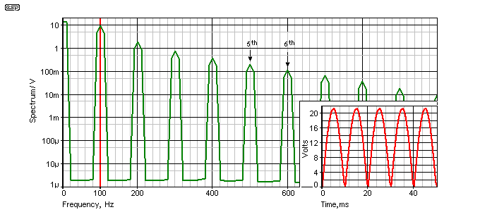
When the input sinewave (from the mains transformer) is full-wave rectified, its frequency is doubled, so 50Hz becomes 100Hz and 60Hz becomes 120Hz. Figure 1 shows a Fourier transform of the 100Hz signal, and it highlights the two harmonics we are interested in restoring. Inset is the voltage waveform for a 50Hz full wave rectified sinewave input. To obtain 600Hz, for 50Hz we need the 6th harmonic of 100Hz, and for 60Hz we need the 5th harmonic of 120Hz. Although this graph was only created for 50Hz mains, the relationships don't change, so the relative harmonic levels are accurate for any frequency (within reason). Both of the harmonics are at an acceptable level to allow easy reconstruction of a 600Hz sinewave. The 100/120Hz waveform is also passed through a zero crossing detector (Q1 in Figure 3) and a Schmitt trigger (U1A), and this not only removes noise that may cause a false signal, but also gives us higher amplitude harmonics.
Once the waveform shown in the inset of Figure 1 is converted to a pulse waveform by the Schmitt trigger, the harmonic structure is greatly improved, making it even easier to extract the wanted 600Hz from the synchronising signal.
After the 600Hz signal is generated, it is directly locked to the mains, so any small variation will be tracked exactly. All that remains is to divide the 600Hz by 10 to obtain 60Hz, or by 12 to get 50Hz. These are both integers, and suit common digital dividers perfectly. The final output frequency will track any small mains frequency deviations and will provide the precise number of cycles per day that we expect. For example, if the 50Hz mains input frequency were to increase (or decrease) by 1Hz, the 600Hz output will increase to 612Hz or drop to 588Hz, so as the mains frequency changes the output remains in perfect step.
The idea of rewinding synchronous clock motors for low voltage operation is discussed at some length in the article Old Synchronous Clocks. While it is possible to use the circuit described here with a transformer to obtain the original voltage, it is far easier (and considerably more efficient) to rewind the clock to run at a safe low voltage. This means that the clock can never be used at the normal mains voltage again, but this is a good thing from a safety perspective.
While the article referenced above suggests rewinding for 16V AC operation, for this application I recommend 12V. There are inevitable losses in any electronic circuit, and obtaining a 16V AC frequency changed output from a 16V AC plug-pack supply is difficult without introducing even more losses. Using the suggested 16V AC supply is easy because the plug-packs are readily available at reasonable prices, and rewinding the clock motor for 12V means that the system losses are minimised, while still having plenty of drive capability available.
While it looks complex, the various stages are actually quite simple. The block diagram shown in Figure 1 has all the main building blocks. Each section can be built and tested in order, so that any problems are isolated before you have a complete circuit to debug.

The first stage is the power supply. This includes a bridge rectifier, filtering, and a low current 10V DC supply used by the analogue stages. This also powers the CMOS logic dividers. The heart of the frequency changing scheme is the 100/120Hz full-wave rectified (and therefore doubled in frequency) signal used to create the 600Hz reference frequency. This is extracted directly from the 16V AC power input. Q1 is shown as a BC549, but any NPN small signal transistor (e.g. 2N2222) will work fine. Q1 is designed to detect the point where the waveform is almost zero, and delivers a short pulse. This circuit is commonly known as a zero crossing detector. A Schmitt trigger circuit then ensures that random noise pulses don't generate a stray pulse that may cause the clock to gain. This short pulse has a very high harmonic content, and ensures that the 600Hz signal is accurately locked to the mains frequency.
The next stage is a dual tuned filter. This is a bandpass filter, which rejects frequencies higher and lower than the selected frequency. Each stage is tuned to 600Hz using a multi-turn trimpot. Even if the filter is not perfectly tuned, the output will still be 600Hz, but reduced in level. It is the ability of the filter to pass the exact frequency applied that allows the circuit to accurately track small changes in the applied mains frequency.
The next stage depends on the desired frequency. It is entirely possible to convert 50Hz to 50Hz (or 60Hz to 60Hz), but to do so is rather pointless. Assuming you have a need for a 60Hz supply, the 600Hz reference frequency is divided by 5 to give 120Hz. For a 50Hz output, the 600Hz signal is divided by 6, giving 100Hz.
The next stage divides the output by two. This was done separately for two reasons. Firstly, obtaining 50Hz from 600Hz requires a total division by 12, while 60Hz requires a division by 10. To be able to divide by 12 we'd need two stages anyway, and the scheme shown allows the divider circuit to use common ICs. The main reason however, is that to obtain a clean 50/60Hz sinewave output, the digital signal must have an almost perfect 50% duty cycle. While other duty cycles will work, more filtering is needed to get a good result.
By using a separate 4013 divider, the output will be as close to a perfect 50% duty cycle as can be achieved, making the final filter less complex. The output from the 4013 is then filtered by another bandpass filter, this time tuned to the desired output frequency (50 or 60Hz).
The final stage is a push-pull power amplifier. Allowing for circuit losses, this is able to produce an output of about ±17V (12V RMS) without distortion. A bit of distortion won't worry a synchronous clock motor, so a bit more level is available if really needed. The two power amplifiers are cheap power amplifier ICs. A cheaper option would be to make the amps using discrete transistors, but the end result is actually more complex.
Because the power supply is the first thing needed, it will be covered first. The zero crossing detector, two Schmitt triggers and the 600Hz filter are included in this circuit block because they are directly related to the power supply. There's actually nothing complex about the circuit, although the uninitiated will surely disagree.

The incoming 16V AC is first rectified by D1-D4. The main power supply is fed via D5, and consists of a filter capacitor (C1), a 10V DC reference signal derived from R1 and D7. This reference signal is used by all the analogue stages as well as the digital dividers.
Note: There was an error in the diagram, with R4 shown going to the rectified output instead of the DC supply. This resulted in very low pulse amplitude from Q1. The error has been corrected. The values of R7 and R9 have also been changed, as they were too low before and the output would clip. This makes tuning more difficult.
D5 isolates the filter capacitor (C1) to ensure the a clean full-wave rectified signal at double the mains frequency is available across R3. The full-wave rectified signal is now at twice the mains frequency, and this is used to switch Q1. Q1 is off only when the 100/120Hz signal is almost zero, giving a very short pulse. The pulse is processed by a Schmitt trigger circuit that is designed to reject momentary noise spikes that could affect the output frequency. The output of the Schmitt trigger is fed to two cascaded 600Hz filters (U1B and U2A), and then to the squarewave shaping circuit, U2B. U2B is configured as a Schmitt trigger to ensure a clean squarewave with good noise immunity. The output squarewave is clamped to the 10V digital supply with D6 to prevent damage to the CMOS integrated circuits.
Use an oscilloscope and optionally a frequency counter (many digital multimeters include this function) to measure the frequency at TP1 - it should be 100Hz if you have 50Hz mains, or 120Hz for 60Hz mains. The waveform should be narrow pulses. Next, measure the output frequency from the first tuned filter at TP2. The tuning has a fairly wide range, so you need to ensure that it is tuned for maximum output level at 600Hz. Signals are available at 100Hz intervals (100, 200, 300, 400, 500, 600, 700 Hz, etc.), so it's important to make sure that the correct frequency is tuned. See Test & Alignment below for the exact tuning procedure.
The second filter can now be tuned for maximum output using the same procedure, using TP3. This one is a lot easier to tune properly, because the first filter has already removed most of the unwanted frequencies. The voltage at each test point should be measured with an oscilloscope, but a true AC meter can be used at a pinch. If your meter gives a reading other than zero when you measure between the cathode of D7 (10V DC) and GND, then you need to use a capacitor of around 100nF in series with the meter to reject the DC component.
The frequency divider circuit consists of either the 50Hz circuit or the 60Hz circuit. If you live in a 50Hz country, you'll almost certainly be building this circuit to obtain 60Hz, so you build only the 60Hz section. Naturally enough, those in 60Hz countries need only build the 50Hz section. Because the frequency needs to divided by 5 to obtain 60Hz, an additional logic device is needed in the form of the quad NAND gate (U5). Only two sections are used, the remaining inputs being connected as shown.
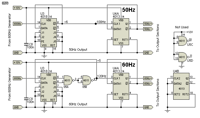
The frequency dividers are CMOS devices, so make sure that you use the normal precautions against static electricity when handling them. Connect the ICs as shown, making sure that you select the circuit that provides the wanted output frequency - not the mains supply frequency.
The second divide by two stage (U4A) ensures that the output is a perfect squarewave, with equal on and off times. The outputs of the U3 dividers are a pulse waveform, and this is much harder to filter into a clean sinewave. This is the reason that 600Hz was selected, as it allows for the final divider stage. Had the 300Hz common frequency been used, the dividers are more difficult (divide by twelve is not a common function), and the final filter would have been far more complex.
If you find it more convenient, you can use U4B instead of U4A for the final divide by 2 stage. The output of this stage is a near perfect squarewave at the selected frequency. This signal now passes to the final low-level stage, either the sinewave filter or the modified squarewave driver.
Note the points marked 100Hz and 120Hz. These are used (along with U4A) to generate a modified sinewave rather than a 'true' sinewave. The modified sinewave has the advantage of being more energy efficient (less wasted power), but synchronous motors usually don't care about the waveform, so use whichever one you prefer.
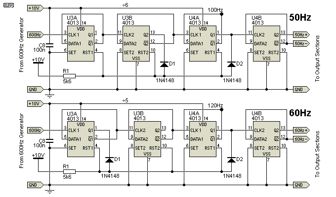
The second divider option uses only a pair of 4113 dual D-Type flip-flops, with a bit of resistor-diode logic to create an AND gate. The two circuits are almost identical, except that D1 is taken from either the second D-Type (to divide by 6), or the first (divide by 5). In the first case, when U3B-Q2 AND U4A-Q1 both 'low', the counter is reset. For 60Hz output, we divide 600Hz by 5. It all looks a bit odd, but it works, and means that you only need a pair of 4013 ICs rather than a 4013 and a 4018. The final 4013 flip-flop is used to produce an output squarewave as before.
This filter is a bandpass type (just like the 600Hz filters), but only one stage is needed. As with the frequency divider, you need to build the one that suits your desired frequency, not the mains frequency where you live. The distortion is more than acceptably low, and will normally be considerably less than the distortion of the normal household mains waveform.
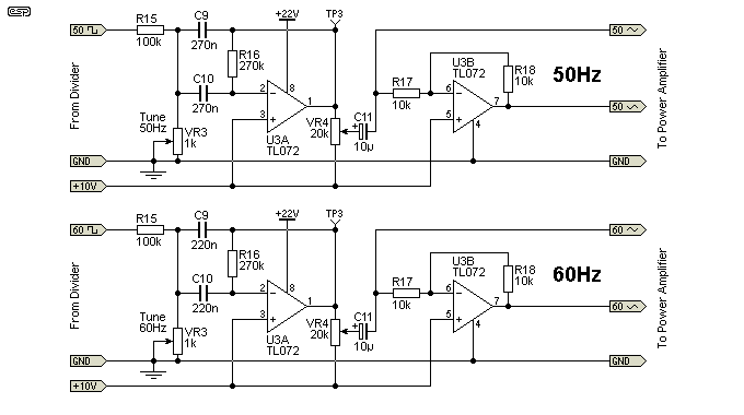
Having selected the correct frequency for your application, the filter must be tuned. Using the output from the divider and measuring AC volts the same way as before, adjust VR3 for the maximum signal level at TP3, as measured on an oscilloscope or digital voltmeter. Typically, the maximum obtainable will be around 5V RMS (a little under 16V peak-peak if you use an oscilloscope).
The second stage is simply an inverter, so the power amplifier ICs each get an opposite signal. The level control (VR4) is to allow you to set the voltage to the power amplifiers, so the output is at 12-13V RMS.
The sinewave filter is entirely optional though - all synchronous motors I've come across so far will run just fine with a squarewave or 'modified sinewave' drive. The so-called modified sinewave is really just a squarewave, but has a well defined and very obvious 'dead band' where the output remains at zero volts. The great advantage of this arrangement is that power dissipation in the output stage is dramatically reduced. Figure 5A shows the waveform that has the lowest distortion.
To ensure that the RMS and peak values are the same as a true sinewave, the 'on' time should be exactly 25% (positive and negative). However, if the 'on' time is 33.33%, this cancels all harmonics divisible by three (use 390k for R15 and R16). The 3rd, 9th, 15th (etc.) disappear, which might allow the motor to run cooler. To achieve either of these, R15 and R16 will be replaced by trimpots, allowing the duty cycle to be accurately adjusted for positive and negative half-cycles.
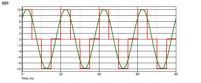
The ideal waveform has a 50% off period during each half cycle, with a corresponding 50% on time, which provides the same peak vs. RMS values as a sinewave. The ratio isn't especially critical, but both timers must be identical. Voltage waveform distortion is about 48% (this is very high), but it doesn't bother most appliances at all. The peak voltage needs to be about ±17V for 12V RMS output, and this makes the power supply design a little easier too. With a 50% 'on' time, RMS and peak values are the same as a sinewave. A sinewave is shown superimposed over the modified squarewave for comparison. The important part is that there are no even harmonics. These create a DC offset that makes driving a transformer very risky.
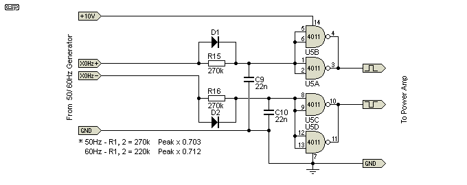
There is no need for a filter, the waveform is easily created using a couple of simple timers based on logic gates. The general idea is shown above, and this will work fine in most cases. The circuit is simple and requires no adjustment, but the capacitors should be matched to minimise DC offset. It can be used for both 50Hz and 60Hz as shown, although you might prefer to reduce the value of R15 and R16 to 220k for 60Hz operation. The output of this circuit can be used to drive the amplifier shown in Figure 6A. You could also use the Figure 6 amp, but it will run hotter and distort the waveform.
This uses both outputs of the final flip-flop, and that ensures that the output has a 'perfect' 50:50 mark-space ratio. It will work with either divider circuit. The 4011 quad NAND gate uses paralleled sections to ensure maximum drive current to the power amp. It's not essential, but otherwise they aren't used and have to be disabled. You can also use a 4584 hex Schmitt trigger inverter, with three sections in parallel for improved MOSFET gate drive.
This is the only irksome section. There are some IC amplifiers that would otherwise be ideal, but their maximum permissible voltage rating is too low to be useful. As a result, we need to use a device that is far more powerful than really needed, simply to make it work properly. While a discrete (individual transistors etc.) design would probably be cheaper, in the long run it just makes the whole project more difficult, with more opportunities for mistakes.
The LM1875 (or TDA2050) is rated for a maximum supply voltage of ±25V, but in our application it will be operating with a single 22V supply. Because of the relatively light loading, only a small heatsink will be needed. Do not be tempted to run the ICs with no heatsink, as they will overheat very quickly.
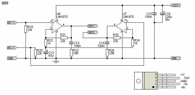
The power amp consists of two LM1875 or TDA2050 power opamps. Use the one that you can get most readily or whichever is the cheaper. They are essentially identical, and there is no benefit to using one over the other. They need to be mounted on a small heatsink - if the supply is built into an aluminium case, the case itself will make an excellent heatsink. The AC output voltage is measured between the two outputs, and should be about 12V RMS at the frequency you need.
The two power devices may be connected directly to the heatsink, using heatsink compound (aka silicone grease) and mounted using the screw hole provided. The mounting tab is connected to the -Ve supply (GND in the circuit shown), which effectively grounds the chassis. This does mean that the AC input connector must be isolated from the case, or a short-circuit will be created via the diodes. The power opamps are almost indestructible, but do be careful to ensure that neither output comes in contact with ground or positive supply. Like the rest of the project, the power amp can be tested by connecting to the previous stage.
VR1 is used to set the output level. If it is set to maximum, the output will be almost a squarewave, but you can simply use your multimeter set to AC Volts to measure the voltage between Out1 and Out2. Set VR4 (Figure 5) to obtain about 12-13V RMS. If you have an oscilloscope, look at the output waveform. Oscilloscope measurements must be from GND to Out1, and GND to Out2. A small amount of distortion is normal - the top and bottom of the waveform will probably be slightly clipped. This is quite ok, and is actually a benefit, because the power dissipation of the amplifiers is reduced. The clock motor won't care at all.
Distortion will be significantly lower than you'd normally expect from the mains supply, and will typically be less than 5%. This is a 'true sinewave' converter, and can produce much lower distortion than most commercial systems that are expected to drive much higher powered appliances.
If you wish to use the modified sinewave described above, this dramatically reduces the power dissipation in the power ICs and lets you run the system on a lower voltage. The circuit diagram is shown below - while it looks similar, there are some very important differences. It is designed to operate in full clipping, as this is the most efficient way to run any amplifier. You'll still need heatsinks, but they will be much smaller while allowing more power if needed.
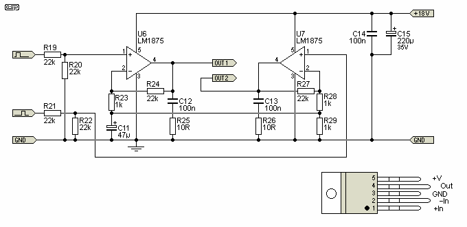
Note that the supply voltage is lower than the true sinewave version, although the RMS output voltage is roughly the same. This is due to the characteristics of the waveform. This type of output is very common indeed - small car inverters (12V to 120V or 230V) and even some quite large inverters (up to several kW) may use this method. It's cheap, but works well for most appliances.
Please do not assume that the two amplifiers are interchangeable, because they're not. The differences are subtle but important.
While the circuits might appear complex, in reality they aren't. If each section is built in turn, it can be fully debugged before going on to the next. This prevents a cascade of errors that could make fault-finding and repair all the more frustrating. The parts are all cheap and readily available, and a systematic approach to construction will result in very little grief. Provided you work through each section in turn and double-check each new section as it's completed, construction will be straightforward. All resistors shown in the schematics are 0.25 or 0.5W, preferably 1% tolerance metal film, and capacitor voltages (where shown) are the minimum. Higher voltage caps are quite alright to use. Unmarked capacitors are polyester, rated at 63 or 100V DC. All trimpots should be multi-turn, since these are far easier to adjust accurately.
If the schematics are followed without mistakes the whole unit should work first up. There are a few things that need to be done to ensure that the filters are properly aligned, and for this you really do need an oscilloscope. While it can be done without one, the end result may not be 100% stable.
The first test of any project is to ensure that the power supply voltages are correct, and this is no exception. If a 16V external transformer is used as recommended, the main supply voltage will be around 22-23V DC. A little higher or lower is ok, but if it's less than 20V there is almost certainly a mistake that is overloading the supply. The 16V AC should be applied first via a 10 ohm 1/2W resistor. This will burn out if there is a problem. Test the power supply first - this is the section that contains D1 to D6, R1, C1 to C3, and Q1 with R2 to R4. Once you are sure that this section is fully functional, the remainder of the Figure 3 circuit can be connected, and the filters aligned.

The first filter is by far the most critical. Using your oscilloscope, verify that the voltage at TP1 is as shown in the red trace. Small variations are not a problem, but even these are unlikely - this part of the circuit is extremely predictable. The red trace is the mains synchronisation (trigger) pulse, and is responsible for maintaining a reference 600Hz signal that is locked to the mains. Next, look at TP2.
The voltage here can be seen to fall to the minimum (a little under 2V) when the mains synchronisation pulse is applied. The signal then oscillates with a reducing amplitude until the next trigger pulse is received. The critical part of the alignment is the exact point where the trigger pulse arrives. As you can see from Figure 7, this pulse occurs just as the seventh cycle is starting. This will be the sixth cycle when 60Hz mains frequency is used, as shown in Figure 8.
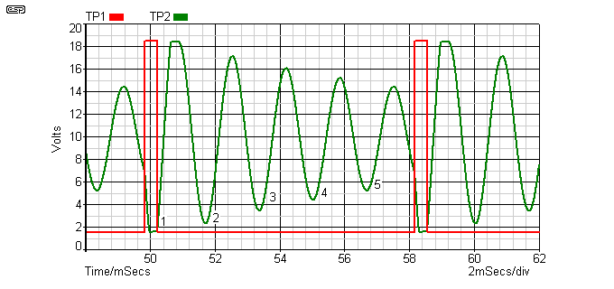
Making sure that the trigger pulse arrives at the right time for your mains frequency is fairly critical. You need to be able to count the number of cycles in between each trigger point, so expect to experiment with the oscilloscope's trigger level to get a stable image. Figure 9 shows incorrect and correct alignment points, showing the last cycle before the next trigger pulse. Note that the trigger pulse should cause the waveform to go to almost zero volts, but without any glitches that could cause problems with long-term stability.
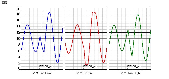
Once the first filter is tuned properly, make sure that the correct number of oscillations occur between trigger pulses as shown in Figures 7 and 8. The second filter can now be tuned to get the maximum possible level at 600Hz. This will be fairly easy to do, because the hard part is done. When the second filter is properly tuned, you will see a stable 600Hz sinewave that shows slight clipping. You will need to adjust VR2 in one direction until the amplitude just starts to fall, then in the other until the signal has fallen by the same amount. Set VR2 to the mid point of the two settings.
The digital dividers will work exactly as planned if they are wired correctly. If your multimeter has a frequency counter function, verify that pin 3 of U4A is either 100Hz or 120Hz, depending on the version you are making. The output of U4A will then be at either 50 or 60Hz.
The 50/60Hz filter may now be aligned. Simply adjust VR3 to get the maximum peak to peak level. If the filter is way off-tune, you'll see a distorted waveform at a fairly low level. When tuned, the waveform should look like a nice clean sinewave, and will be at the maximum level possible.
Adjust VR4 to get 12V RMS (as measured on your multimeter) between the two outputs. If you examine the outputs on the oscilloscope, do not connect it between the two outputs, but measure each amplifier's output between the output terminal and ground. A clean sinewave of at least 18V peak to peak should be available from each output.
Firstly, I must issue a warning. The output from a transformer operated in reverse to convert a low voltage to something approaching mains voltage is just as dangerous as the 'real' mains. Should you contact both wires at once, you may receive a fatal electric shock. The current available is quite sufficient to kill you, so all experiments must be done with great care. The new frequency changed mains voltage must be treated the same as any other mains voltage, with great care taken with insulation, and proper wiring techniques suitable for the voltage used.
If you are unsure, then this process should not be attempted. The transformer is used in reverse, so we apply low voltage to the secondary, and take the high voltage from the primary. Strictly speaking, this means that the secondary is now the primary and vice versa, but to minimise confusion I will use the terms as they are applied to the transformer windings as originally intended.
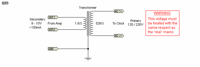
Transformers can be confusing, not because they are inherently weird, but because compromises are always made during manufacture. I tested a 240V/12V transformer I had in my workshop, and tried it in reverse to get a high output voltage from a small power amplifier (using the same IC as shown above). The transformer is rated at 7VA, and produces 13.5V on the secondary with no load. Maximum current is 580mA (12 x 0.58 = 7VA). The transformer ratio is therefore 240/13.5 = 17.77:1
Operating the transformer in reverse, if we were to apply 13.5V RMS to the secondary, the no load output voltage should be 240V, but will actually be a little less due to transformer winding resistance (1.6 ohms for the one I tested). Once the transformer is loaded, this will fall further. With a secondary current of 30mA (enough for two typical clock motors), the output voltage falls to 178V. This obviously means that the selected transformer is marginal, and probably cannot be used. 14V RMS is about the maximum we can expect from the power amp shown in Figure 6, so there is no more voltage available. There are two things that need to be done to get enough voltage to run a clock ...
The important thing to realise is that there are losses in transformers, and we must compensate for these or we may not get sufficient voltage to run the clock. This becomes especially important if a transformer designed for 60Hz is to produce full voltage at 50Hz. The transformer needs to be larger than expected or the losses will be too great. I tested the transformer I was using at 40Hz, and measured a small additional reduction of voltage.
The actual output voltage needs to be set with the clock motor's coil attached, as it will fall even with a small load. The transformer was never designed to be operated this way, and we have to accept that there are limitations that are not normally considered.
The main issues are the transformer's magnetising current and the winding resistance of the transformer. By using a transformer that is considerably larger than might seem necessary, these losses can be minimised. If the transformer is too small, magnetising losses will cause the transformer to draw more current from the amplifier, even when not doing anything useful (like powering your clock). The transformer I tested drew 85mA with 9.7V applied, so would draw about 130mA with no load at 13.5V. Within reason, a larger transformer will draw less - especially if it's a toroidal type.
We also have to consider the current drawn by the clock motor. If it draws 20mA and the transformer ratio is 20:1, the amplifier will have to deliver 400mA. When a transformer boosts the voltage, the input current is increased by the same ratio. So if the voltage is increased 20 times, the input current must be 20 times the output current.
All in all, it is far simpler to rewind the clock motor, as all these nuisance issues just go away, and you have no further concerns about possible insulation breakdown or overheating. Because the voltage can be adjusted at will, you can still get the clock to work if you underestimated the number of turns - simply reduce the voltage until the clock runs properly and remains barely warm.
The end result is something that is not available as a DIY project anywhere else on the Net that I'm aware of, and it produces an output that is perfectly synchronised to the incoming mains. Although the suggested use is for synchronous clocks, it can be used anywhere that frequency needs to be changed. However, clocks are probably the only 'appliances' where the exact mains frequency is important. For everything else, a small error causes no problems at all, but no other electric machine is expected to be as accurate (long term) as the humble clock.
This project should be able to run 2 or 3 clocks quite easily. If normal mains voltage is required, it might be possible to use a transformer in reverse. If a 12V winding is connected between the amp outputs, the 230V or 120V winding will be at close to the full mains voltage. The transformer needs to be rated at around 20VA, because the losses in smaller transformers are likely to be excessive. As noted elsewhere, it is generally far safer to rewind the clock for low voltage operation, and that removes the need for extra transformers and the safety features that are needed for anything that can deliver mains voltages.
It may be possible to use a PIC (programmable microcontroller) to achieve the same result, and this would reduce the component count considerably. The zero crossing detector is still needed, but there is no requirement for the Schmitt triggers or 600Hz filters. It is likely that the divider ICs would still be easier than trying to perform the division in software. The output would be filtered using the Figure 5 circuit as shown, and the power amps are also unchanged. I've not done any work on this idea as yet, but may do so if there is sufficient interest. Using a PIC may be simpler, but is far less interesting. A DSP (digital signal processor) based system could also be used, but the ICs are expensive, and the programming effort is way out of proportion for the intended use (several $thousand is not unreasonable). The solution shown is probably as simple and cheap as you're likely to find - assuming that you can even find a similar product anywhere. I couldn't.
This is an original design by Rod Elliott, and no references are available since no-one has published a similar design (or a design using similar principles) on the Net or elsewhere that I have found. As noted below, the design is copyright © Rod Elliott, 2009, all rights reserved. This project may not be used commercially, it is for individual/personal use only.
 Main Index Main Index
 Clocks Index Clocks Index
|