
|
| Elliott Sound Products | Class A Amplifiers - Part 2 |
 Main Index
 Articles Index
 Class-A Part 1
As discussed in Part 1, there has been a resurgence of two 'ancient' technologies - vacuum tube (valve) amplifiers and Class-A systems. The big question is ... is there a difference? This part of the discussion looks at the differences in the output stages only - no feedback is used in any of the following, so the performance of the final stage can be assessed.
The Class-AB output stage is essentially the same as that used in Project 3A), and this is compared with a Class-A emitter follower circuit using exactly the same circuitry. Both were operated with zero feedback, and the Class-AB stage was run at a quiescent current of 14mA vs. 2A for the Class-A circuit.
The Class-A version was operated using an ideal current source - a real current source will not be quite as good, however the difference in practical terms is very small (this was verified in a simulation).

Figure 1 - Class Comparison Simulation Circuits
A description of the circuits is in order before we continue. The Class-AB output stage uses current sources to bias the bases, and 1,000µF coupling caps to the signal source. This is simply to allow the circuit to be biased correctly for the simulation, and has no effect on distortion. Because there is a small difference between the positive and negative halves of the circuit, the current sources were actually very slightly unbalanced to get less than 10mV DC offset at the output.
Quiescent current is set by the diode and 39 Ohm resistor, and was just over 14mA for the simulations used in this article.
The Class-A amp uses the same transistor configuration, but the bias is supplied by a much smaller current source - again, to obtain less than 10mV DC offset. I used a 2A current source rather than semiconductors to ensure that the results were not adversely affected by an imperfect current sink. Naturally, this choice is removed for a real amplifier.
Different results would be obtained using a Darlington emitter follower, however the difference in real terms is far less than will be caused by actual (as opposed to simulated) transistors. A quick check indicates that the Darlington configuration has slightly less second harmonic distortion, and less distortion overall. This will not necessarily be the same in a real amplifier. The compound (Sziklai) pair generally shows lower distortion than an 'equivalent' Darlington pair.
It is worth noting that although the Class-A amp performs better with a Darlington, the Class-AB circuit is significantly worse - even with higher quiescent current - this has been known for quite some time, but is still ignored by many designers.
The first test was at close to full power - 15V peak (30V P-P) was used to ensure that both circuits were well away from clipping, as this would affect the results making a proper comparison impossible.
Logically, one would expect the Class-A emitter follower to be better (have lower distortion) but it doesn't! Distortion is 0.41% for the Class-A version, and 0.098% for the Class-AB. Spectral content shows that the Class-A circuit has higher harmonic levels than the Class-AB circuit up to about 6kHz, and it is only after this frequency that the Class-A amp shows an advantage. Even in this form (widely believed to have predominantly second harmonic distortion), there is considerable third harmonic distortion, as well as 4th, 5th, etc. Distortion falls to very low levels (-100dB) at 6kHz (6th harmonic).
By contrast, the Class-AB circuit has lower distortion overall, with low order harmonics almost an order of magnitude lower than Class-A. However, the spectral graphs show that high order harmonics are at a much greater level. Where the eighth harmonic was 100dB down in the Class-A circuit, the 31st harmonic was 100dB down in Class-AB. Which is preferable? I shall leave that up to the individual reader. I know for a fact that I can't hear distortion that is -100dB ... perhaps some people can, but I've not met any.

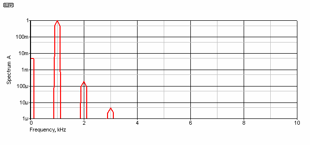
Figure 2 - Spectral Results for Class-A Output Stage
As you can see, the second harmonic (2kHz) is about 48dB below the fundamental, and the remaining harmonics are below the -100dB level by 8kHz (the 8th harmonic). The level at 8kHz is actually -102dB referred to the fundamental. This cannot be considered a bad result. With the addition of feedback, these components will be reduced further, but it is also to be expected that any 'real-world' semiconductors will perform worse than their simulated counterparts.
 |
Note that this is a single-ended Class-A stage, and it is this very configuration that is said to have predominantly even order harmonics (second, fourth, etc.). Instead of what is normally
expected, we have an even progression of harmonics, with both odd and even represented in an orderly progression. To obtain predominantly even order harmonics, common 'wisdom' claims that the
output stage should be operated as a common emitter amplifier (an emitter follower as shown is common collector). This is analogous to a common cathode stage as used in most single-ended triode
(SET) amps. Use of a common emitter stage will increase the levels of distortion dramatically - a quick test indicates that using the same topology for the stage but operating it as common emitter increases distortion to 8.56% at 30V P-P output, and it is still 1.61% at 2V P-P (these are the same levels used for all tests described in this article). This is hardly an encouraging result, but it does match the typical distortion levels of a SET Class-A amp. Adding some emitter feedback will reduce this very high distortion to something more tolerable at low levels (I measured 0.23%), and will also reduce distortion at higher voltages/ powers. At a little under 30V P-P, distortion was 3.8% - hardly awe inspiring. There is still a significant number of odd order harmonics at all power levels, and it is probably fair to say that very few (if any) amplifiers actually produce only even order harmonics. It is easy to eliminate even order harmonics, but very difficult to eliminate odd ordered ones. This is despite any advertising material that claims the contrary. |
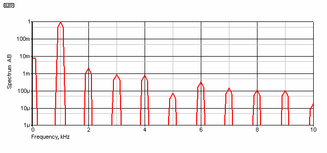
For Class-AB, the second harmonic is 63dB below the fundamental, but there are higher order harmonics present at ever diminishing levels. Although it is unlikely that any of these would be audible, it is just this effect that some people claim ruins the sound. Again, feedback will reduce these levels, and in both cases shown, the system noise will help to mask any distortion products. Do not expect real power transistors to equal these results, because it is almost a certainty that they won't (as with the Class-A example above).

Figure 3 - Spectral Results for Class-AB Output Stage
Bear in mind that the 1mV level shown represents -83dB, and the 100nV minimum level equates to -163dB referred to the 15V peak level at 1kHz. A great many of the harmonics displayed are so far below the noise floor that no affordable test instrument would be capable of resolving them (and this includes the ears of the vast majority of people - i.e. everyone!).
It is at low levels that we see some differences, and the performance differences are more like we might expect. For the Class-AB circuit, it is important to ensure that the test level is high enough to ensure that the transistors will turn off completely - at very low levels the circuit will operate in Class-A, and this would give us an unrealistic distortion level.
With 1V peak output (707mV RMS, or 2V P-P), this ensures that the Class-AB circuit is working as Class-AB. Now we see the effects of crossover distortion - even though it is not visible on a waveform graph. Total Harmonic Distortion (THD) is now 0.245% for Class-AB, but a more respectable figure of 0.098% for Class-A. This is still not wonderful, but is easily improved with feedback.

Figure 4 - Class-A Output at 62mW
Here we see the harmonic content at 62mW output level. There are only a couple of low order harmonics present, with everything beyond 4kHz well below audibility. The minimum level of 1µV is 120dB below the 1V peak signal level, and can be considered so far below the noise floor that it is not worth considering.

Figure 5 - Class-AB Output at 62mW
Things are not quite so rosy here. However, even with an overall THD of 0.245% it still cannot be considered a particularly bad result. Again, feedback will reduce this further, and is easily capable of bringing THD to below 0.01%. Everything beyond 4kHz is more than 60dB below the signal level, and that will be approaching the amplifier noise floor, and well below the listening room noise.
To explain that last point, assume a typical high-efficiency loudspeaker, with 100dB/W/m (very high efficiency by today's standards). 62mW is 12dB below 1W (close enough), so the peak level at 1 metre in the room is 88dB SPL. Since the upper harmonics are all more than 60dB below the fundamental, that makes them less than 28dB SPL. A very quiet room indeed would be needed to be able to hear a signal at only 28dB SPL, and it would probably be impossible in the presence of the fundamental.
As shown above, Class-A will give vanishingly low levels of distortion at low levels. Based on many amplifier tests over the years, I also know that a Class-AB amp can do exactly the same, but at all levels below clipping (not just low levels). Whether the overall advantages and disadvantages of a Class-A amp are worth the effort is entirely up to you - if having one makes you feel better (and especially so if you build it yourself), then there is no reason to avoid having one.
Of course you will need sensitive speakers, otherwise the available power at any sensible dissipation is just too low to be useful. In a biamped or triamped system, Class-A is ideal for tweeters. Will you hear a difference? I don't know - it depends on the amp, your hearing, and whether you perform a true blind test so you are completely unaware which amplifier you are listening to at any time during the test.
Using switching MOSFETs can't be considered a particularly good idea for Class-A operation. If used as source followers the performance can be alright, but usually still not good enough without feedback. When used as the main amplifying device they are particularly poor, with distortion well above that which anyone could consider acceptable. Adding an additional gain stage so that a high feedback ratio can be applied will reduce the distortion - generally in a direct relationship to the feedback ratio. This rather negates the idea of a 'simple' Class-A amplifier.
 Main Index
 Articles Index
 Class-A Part 1