

|
| Elliott Sound Products | Active Vs. Passive Crossovers |
 Main Index
 Articles Index
In the article Benefits of Biamping, I discussed the many advantages that are to be had by using separate amplifiers for bass and mid+high. There is also a section devoted to tri-amping (for a typical 3-way system). Essentially, the ideal arrangement is to use a separate amplifier for each loudspeaker driver in the system. Although there are still many who consider this to be overkill, the advantages are so compelling that there is no reason not to adopt this approach as a matter of course.
Of course, if the speaker arrangement uses two drivers in parallel (for example the well known MTM or D'Appolito topology), a single amp may drive both mid-woofers - dual amplifiers will usually not give any major benefit in this setup.
One area of the original article was not covered in sufficient detail - driver control. While I firmly believe that the ideal situation is to damp a resonant body at the source, this is not always feasible or even possible. There is also the occasional driver that simply cannot be controlled from 'an ohm away' - i.e. it may require that the source (amplifier) is hard-wired to the driver, with an absolute minimum of resistance or impedance between the two. Some compression drivers (for horn speakers) are an example, where even a few hundred milliohms may allow the driver to do 'its own thing' rather than faithfully reproduce the applied signal.
Driver control (AKA 'damping factor' - somewhat erroneously IMO) is a much touted parameter, and is considered important by the majority of hi-fi enthusiasts/ audiophiles. Indeed, even where a defined amplifier output impedance is used (such as 4 ohms, as used in my own system), this is done to provide a specific loading to the voice coil motor to control the back-EMF that is developed in any electromagnetic loudspeaker driver. The most commonly sought after figure is zero ohms, implying an infinite 'damping factor', but the laws of physics conspire to make this unrealistic.
However, a damping factor of (say) 100 or more is easily achieved, even with typical loudspeaker cables and amplifiers ... or is it?
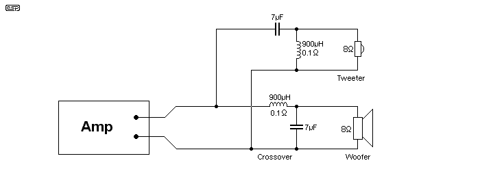
Figure 1.1 - Typical 2nd Order Crossover
There is no attempt on my part to add impedance compensation networks, notch filters, or any of the other typical additions to the circuit, and for convenience I have used purely resistive 'speaker drivers'. My one concession to a conventional design here is that I included 100mΩ resistance in the inductors. Any additional circuitry will affect the impedance seen by the driver - in some cases it will introduce an advantage, in others a disadvantage. I shall leave it to the reader to determine the specific differences (with a little guidance, of course).
One may rest assured though, that the performance changes due to extra circuitry will only modify the performance to a marginal degree - the primary issues remain unchanged.
Now, it must be mentioned that damping factor is (generally) only considered relevant for bass, and specifically bass resonance. It is expected (but not necessarily achieved) that the enclosure itself will be damped with suitable material (polyester 'wool', fibreglass mat, etc.). This is done to ensure that rear cone radiation is absorbed at mid to high frequencies, and this will have an impact on how well or otherwise the speaker cones act as microphones (see below for more details). However, consider that most dynamic (moving coil) microphones have damping materials anyway, so the amount of damping will not affect the signal picked up by a midrange driver that's excited by compression and rarefaction from the woofer. I don't know of any detailed studies that have examined this in great detail, although I'm sure that someone has looked into it at some point. A search didn't reveal anything, but it depends on what one searches for.
There are any number of references on-line to passive crossover capacitors that are claimed to be microphonic, but since most are found in forum posts they probably should be taken with a grain of salt. A forum is rarely a source of reliable information, pretty much regardless of topic or context, as most are filled with opinions rather than facts. Advertisements are even worse, as they only want to sell you something, and facts are generally avoided if they might ruin an otherwise good sales pitch.

Note that the subject matter presented here is a hypothesis, and I have not been able to determine whether the effects described are audible or not. The effects are certainly measurable and are easily simulated, but it's likely that the inherent distortions present in most loudspeaker drivers would swamp the effects described here. There are many issues with even the best moving coil drivers that influence what we hear, and the development of the 'perfect' loudspeaker is a goal not yet achieved (despite marketing claims to the contrary).
The reader should look at this material as 'exploratory' rather than 'definitive' in any way, shape or form.
For the sake of this discussion, we will assume a perfect amplifier, with an output impedance of zero ohms, and zero ohm speaker cables. I know this is unrealistic, but it shows the real situation very clearly - real components will be worse - always!
The exact parameter we will examine is the impedance 'seen' by the loudspeaker driver, over a range of frequencies from well below the crossover frequency, to well above. Conventional logic indicates that this should be as low as possible over the entire frequency range. There has been a concerted effort by amp makers to ensure that their products output impedances are as low as possible to satisfy this requirement. Valve (tube) amps are naturally different in this respect, although that is not part of this discussion.
Figure 1.1 shows the crossover connections used, and the circuit is a conventional 2-way, 2nd order (12dB/octave) Butterworth type. Note that all versions of crossover will have similar response characteristics, although there are significant differences that will be looked at a little later in this article.
To see exactly what happens (and why), we need to redraw the crossover network so that it can be examined from the loudspeaker driver's perspective. As shown below, we see each section of the crossover (high and low pass). This is exactly the same crossover as shown in Figure 1.1, but redrawn. Since we are looking only at the damping, the amplifier is irrelevant and has been removed from the picture. It is assumed (along with speaker leads) to have zero impedance.
Remember that for this exercise, we are looking at the impedance seen by the loudspeaker, as this has a direct effect on the ability of the amplifier to damp the back-EMF (Electro-Motive Force) from the motor assembly. The back-EMF is produced whenever the cone is moved by a current, or the current is removed or changes direction. Inertia of the cone and suspension means that it cannot move or stop instantly, so there will be 'overshoot' and 'undershoot' caused by the cone continuing to move after the applied current has stopped.
A simple demonstration can be done to show that the speaker does indeed generate a voltage and current. Take a small speaker (not a tweeter), and connect it to an unused input on your preamp. Advance the gain of the amp slowly, whilst gently tapping on the cone. 'Thump, thump' says your hi-fi. You can even speak into the loudspeaker, and it will act as a microphone.
 |
Be careful - if you increase the gain too far, you may get acoustic feedback - potentially at very high volume levels. This will do little for your hearing, and may also damage loudspeakers. Make sure you keep the 'microphone' as far from the speakers as possible to minimise the likelihood of feedback. |
This simple test shows that loudspeakers do indeed generate a signal, and it is this signal that the amplifier is meant to absorb, by means of 'damping factor'. A back-EMF signal is generated every time your amplifier sends a signal that causes the cone to move - namely, all the time when you are listening to music (or home theatre). It is this signal that we will investigate in this article, and no other parameters. All dynamic (electro-magnetic) loudspeaker drivers do this - bar none. It should be obvious that if you short circuit the speaker that you used as a microphone, then you will hear no sound from it - this is maximum damping factor, and is what is meant to happen with your loudspeakers.
The phenomenon that you have experienced by using a loudspeaker as a microphone also happens with your real speakers! The woofer will produce a signal that is picked up by the midrange or tweeter, which in turn will generate a signal. This signal should be dissipated entirely by the amplifier to prevent (as far as is possible) the cone moving in sympathy with the soundwaves. As we shall see, this cannot happen as it should with a passive crossover!
Even electrostatic drivers will do the same thing (although by a different mechanism entirely), but their mode of operation is such that the generated signal is of extremely small amplitude (perhaps a few millivolts at the very most). We shall not concern ourselves with this.
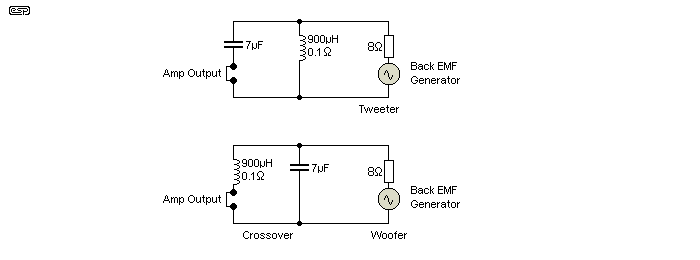
Figure 2.1 - 2nd Order Crossover Redrawn
The generators in series with each 'driver' in the above diagram are to simulate the back-EMF from real-world drivers, and this is exactly the equivalent circuit that exists in reality. The only difference is that I used 8Ω resistors rather than the complex impedance of real drivers. This changes nothing, but makes the following graphs more comprehensible, without the wild fluctuations that would only confuse the issue.
Figure 2.1 shows the crossover network as it is seen by the loudspeaker. The amplifier and speaker leads no longer exist, as they were assumed from the beginning to have zero impedance. The crossover now appears as a simple parallel LC network, with resonance tuned to the crossover frequency. For those who know what this means, the implication is obvious. For the remainder, we have a parallel tuned circuit, and with ideal components (no losses), its impedance is infinite at resonance! That means that at resonance, there is no damping whatsoever, and the damping factor is ... zero!
Next, let's look at the impedance of this network over a couple of octaves below and above the crossover frequency. This gives a more balanced perspective, and we can determine the effective damping over a sensible range. The damping within the stop band (i.e. the band of frequencies the crossover network section rejects) is not so important, as the signal applied to the driver is minimal anyway. There is still the potential for considerable energy within the first octave above the crossover frequency (Xf) for a low pass section, and an octave below for a high pass section, so this is still of some importance.
Figure 2.2 shows the impedance curve of a 2kHz XO, looking backwards from the loudspeaker into its crossover section. I have shown the low and high pass sections here, but they cannot be separated because they are identical (as one would expect, since the inductance and capacitance are in parallel in both cases). There may be small differences with real components having some tolerance, but they do not affect the picture significantly.
Indeed, even adding a 1Ω resistor in series with the short circuit shown (and thereby introducing some real-world losses into the parallel networks), there is only a small change. Naturally, it does not improve the situation.
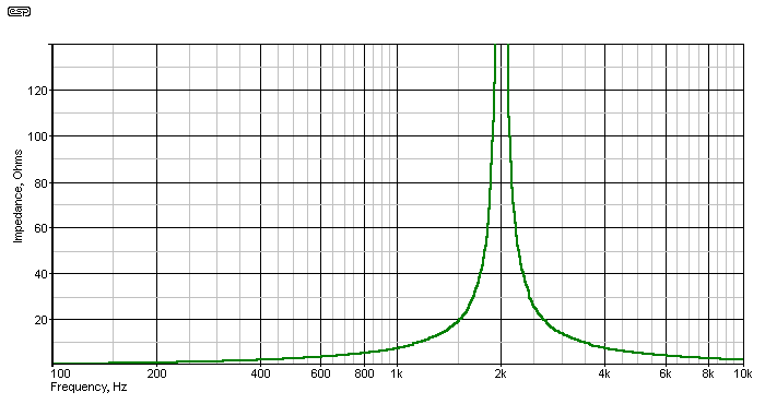
Figure 2.2 - Crossover Network Impedance Seen by Loudspeaker (2nd Order)
The high pass filter impedance response is shown in red, and the low pass in green, although only one is visible since they are perfectly overlayed.
At one octave, the impedance is nominally the same as the design impedance, so for an 8Ω speaker, the network impedance is also 8Ω one octave above and below Xf. This means that the driver sees a damping factor (DF) of one! And this with a perfect amplifier, and superconducting speaker leads. This is not only unexpected, but is potentially quite unsatisfactory, as there is little to damp the loudspeaker back-EMF, so allowing perhaps significant overshoot and undershoot, with inevitable 'smearing' in the time domain. Transients will not be right, as the loudspeaker is still able to contribute a significant amount of its own 'signature' to the reproduced sound.
What about moving further away from Xf ? Well, things improve, but not as much as you might expect or desire. At 2 octaves (500Hz and 8kHz), the parallel tuned circuit has an impedance of 3 ohms, so the DF is now ...
DF = Zspeaker / Zsource = 8 / 3 = 2.66
This is a far cry from the DF of between perhaps 50 to several hundred presented by the amplifier, and for many drivers may be unsatisfactory. Even at one decade (200Hz or 20kHz (i.e. 3.16 octaves either side of the XO frequency of 2kHz), the impedance is still 1.17 Ohms, giving a DF of only 6.8 - in a 3-way system, it is probable that the low-mid XO will be close by the 200Hz figure, and this will introduce even more problems!
In case you might be wondering, using a separate amplifier to drive each section of the crossover achieves exactly nothing. This arrangement is sometimes called 'biamping' by those who know no better, but it is no such thing. I refer to it as 'passive biamping' or 'active biwiring'. Whatever it may be called, it does nothing to fix the issues described, but it does add (needlessly IMO) to the cost and inconvenience of equipping your system.
With an active crossover, the amplifier is connected directly to the driver, and the only thing between them is the loudspeaker cable. The amplifier presents the maximum damping factor at all times, regardless of frequency, and is not affected by the crossover network, since that is also active, and located before the power amp.
The loudspeaker driver now has the maximum control that the amplifier can provide, across the entire frequency range - not just the crossover network's pass band. The difference in damping is quite obvious, and although some (very well behaved) drivers will show little improvement, the vast majority will be much better controlled, and this will show in an impulse measurement. Not at all uncommonly, it will also show up on a swept sinewave frequency response measurement as well, with the amplitude of peaks and dips generally reduced (albeit marginally in most cases).
Well apart from the other advantages of an active system, this is perhaps one of the most compelling reasons to use an active system rather than passive. Not only is it possible to achieve the maximum damping, but if it is determined that a particular driver is best suited to some defined impedance, this can be provided by the amplifier, and will be stable across the frequency range. In some cases, just a series resistor will be sufficient, and even though there will be some power loss, if it makes the driver behave the way it should, then any small power loss is a small price to pay.
In short, there is simply no comparison between the two systems. A passive XO will always add (usually) undesirable impedance to that seen by the driver(s), the impedance is frequency dependent, and ranges from perhaps an ohm or so to almost infinite. The potential for uncontrolled cone movement, intermodulation distortion and loss of performance is so great that it is impossible to determine in advance, but it is all negated in one fell swoop by using a fully active system.
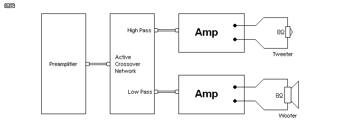
Figure 2.3 - Block Diagram of an Active 2-Way Loudspeaker System
Figure 2.3 shows the essential parts of an active 2-way system. This can be expanded to 3-way (3-way speakers), or 2-way speakers and stereo subs. Four-way systems - or more - are also easily achieved. In contrast to a passive crossover (whether fully optimised or not), each driver has its own amplifier, and each amp has to deliver less power, and over a narrower frequency range. This allows each amp to have an easier time with a less complex load, potentially reducing amplifier heating and overload - even at high listening levels. For a complete rundown of the other benefits, see The Benefits of Biamping (Not Quite Magic, But Close).
The important point here is that each driver has its own amplifier - there is nothing in between except for the cable, and amplifier control is maximised. The demands on the cable are also minimised (assuming that you believe this to be a critical component), and cheap speaker leads in an active system will provide far better performance than expensive leads with a passive crossover.
First, let's look at a 1st order (6dB/octave) network, as this is the network of choice for many audiophiles. Notwithstanding any other problems it may have (due to the shallow rolloff slope), this is still a popular choice and it works very well at low levels. At high power levels the tweeter is at considerable risk, but with around 20W or so (more than enough for 'normal' listening), the tweeter is fairly safe. The impedance seen by the drivers (looking back towards the amplifier) is shown below.
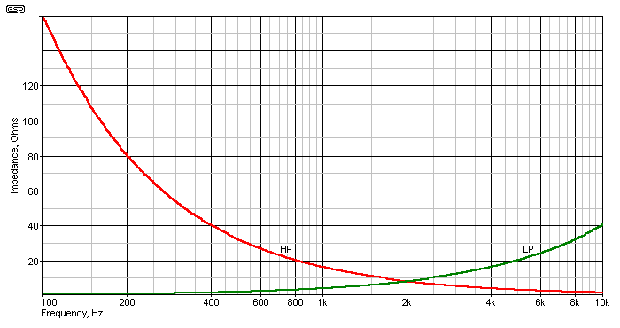
Figure 2.4 - Crossover Network Impedance Seen by Loudspeaker (1st Order)
Again, the high pass filter impedance response is shown in red, and the low pass in green. At the crossover frequency, the impedance is equal to the speaker design impedance, or 8Ω in this case. This provides a DF of 1 - significantly better than a second order filter, but still somewhat shy of ideal. At 1 octave below Xf, the low pass section shows 4Ω - still better than the second order which gave a DF of 2.66 at the same frequency. At one decade, impedance is around 800mΩ, again, an improvement over the second order filter. Unlike second order filters, a first order filter keeps increasing its impedance in the stop band, and at 1 octave above or below Xf, stop band impedance is 16Ω, rising to 80Ω at one decade.
Third order crossovers (18dB/octave) are favoured by many people. They are not as savage as fourth order, and for passive networks are seen as a nice compromise. Reasonably fast rolloff, and no phase reversal as you get with a second order filter. There is also the benefit that you don't need to bother with a Linkwitz-Riley alignment, because 18dB filters should sum flat because of the 90° phase shift between the drivers. However, all is not as rosy as it might appear.
As before, the graph shows the impedance from the speakers, looking back towards the amplifier. The inductors, amplifier and speaker leads are assumed to be ideal - having zero resistance, and therefore the input of the crossover network is simply a short circuit. Adding inductor resistance only makes things worse, not better.
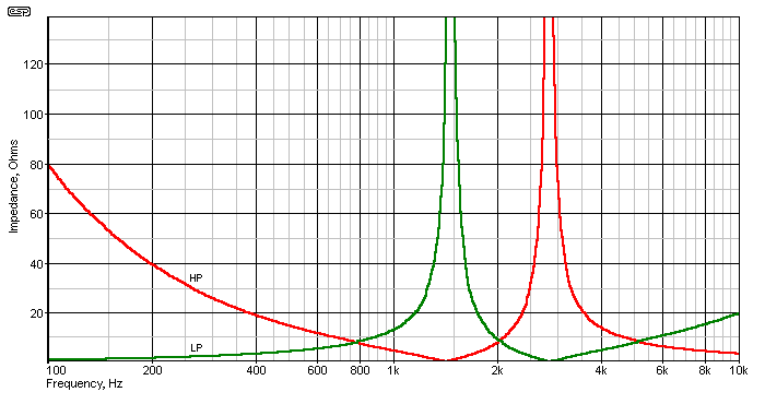
Figure 2.5 - Crossover Network Impedance Seen by Loudspeaker (3rd Order)
Here is where things get really interesting (colours as before). Note that there are two peaks of almost infinite impedance (the maximum is not shown, but will typically be in excess of 200Ω). These are at 1.4kHz (theoretically 1.414kHz in fact) for the low pass section, and 2.8kHz (2.828kHz) for the high pass. This means that there is a point where the loudspeaker driver sees almost infinite impedance to back-EMF, within the normal passband! That this will cause some unexpected results is fairly obvious, but it is unpredictable unless you know the drivers' behaviour at these frequencies ... when driven from source that has frequency dependent damping.
What of the other frequencies - 1 octave and one decade away from the crossover frequency? Because of the behaviour of the third order network, we need to look at Xf as well.
Impedance at Xf is 8.45Ω, and at 1 octave either side of that frequency, the impedance is about 13Ω. This gives a DF of 0.95 at Xf, and 0.6 at the one octave points (within the passband - impedance is much lower in the stopband, at around 4.7Ω). At one decade, passband impedance is 1.58Ω and stopband impedance is about 39Ω.
Interestingly, the impedance seen by the drivers in the stop-band (again at those 'magic' frequencies of 1.414kHz and 2.828kHz) is extremely low, at only a few milli-ohms. This is clearly visible in Figure 2.5 but is probably of little consequence in reality.
We will see almost the same thing with a 'classic' 12dB/ octave network, but the peak for the woofer/ midrange and tweeter are at the same frequency, i.e. the designed crossover frequency. The impedance 'seen' by each driver is over 10Ω from 1.4kHz to 6.2kHz, for a 3kHz Linkwitz-Riley 2nd order network. At the crossover frequency there is no damping at all! Just how that impacts performance depends on the loudspeaker drivers themselves. Ferrofluid tweeters probably won't be affected, but some other types may experience ringing.
By adding (for example) a Zobel to equalise the rising impedance at high frequencies, or a series RLC network to the tweeter crossover to reduce the effect of the impedance peak at resonance, the impedance seen by the tweeter will be lower than indicated above. The woofer is (of course) unchanged by this, but again, a woofer Zobel used to equalise the rising impedance due to voice-coil inductance will have an effect. There is usually no need to add a series RLC network to minimise the woofer's impedance peak at resonance, although it may be necessary on a midrange driver in a 3-way system.
Don't imagine for an instant that impedance correction networks will cure the problem, because they won't. The impedance to back-EMF will still be a great deal higher than you ever imagined, and damping factor will be around unity at best. There is no network that can be placed in parallel with the loudspeaker that will solve the problem, with the possible exception of a 0.1Ω resistor!
That would be a very bad idea, indeed, unbelievably very bad in fact. Your amplifier would see almost a dead short, and even if the amp had an infinite current capacity, a 10W amp would be expected to produce 800 Watts (all dissipated as heat in the 0.1Ω resistor!). Don't even think about it!
But ... there is something you can do. It is called an active system, and you can at last obtain the genuine damping that any amplifier can produce, which is always going to be better than any passive crossover can provide.
What of bi-wiring or 'passive biamping'? Not a sausage worth of difference, I'm afraid. Certainly, there may be some minor improvements in some cases, but they have nothing to do with driver damping. In my opinion, passive biamping (using two amps, but retaining the passive crossovers) is a waste of an amplifier. The same two amps with an active crossover (with the passive XO removed completely from the circuit) will outperform the passive biamp arrangement by such a margin that it's not even worth considering - let alone actually doing it.
This aspect of active versus passive crossovers has received scant attention elsewhere, but it is appears likely that it is at least a contributor to the audible difference between the two systems, even when all else seems equal. As has been shown, there is a major difference between the two types of speaker management, and this is probably the most significant (and important) distinction. As noted in the introduction, the audible effects of an otherwise 'perfect' passive crossover are likely to be negligible, partly due to imperfect loudspeaker drivers and our somewhat limited hearing acuity (it's rarely anywhere near as good as some people think).
It must be understood that passive networks appear to be of sensibly low impedance from the amplifier's perspective, but behave entirely differently towards the driver's back-EMF. This seemingly contradictory situation is caused by the low output impedance of the amplifier, and this causes the impedance of the crossover filters to be asymmetrical (input-output vs. output-input).
Nothing here is magic, nor is it falsified or 'tarted up' for the purposes of this article. Remember that I already stated that we would assume a zero impedance source for all tests. Note that every test shown here can be easily duplicated, using nothing more than a signal generator and a small amplifier wired in series with the loudspeaker (as depicted in Figure 2.1). You will not be able to measure impedance directly, but the voltage (or current) obtained at the crossover's output terminal is directly related to the impedance.
It is very apparent that with a passive crossover, things are not as we would like them to be. Each variant has problems, and as with all things, a passive crossover is a compromise. IMO, this is not a compromise I am willing to make, as the performance is too unpredictable - this explains why so many passive designs require a considerable amount of tweaking before they sound their best - and may still disappoint the listener in critical listening sessions.
This isn't to say that passive crossovers should not be used of course. There are some situations where an active system would make no sense. I use passively crossed mids and tweeters in my PC sound system (with an active xover to the subwoofer), and I also use a pair of (passive) bookshelf speakers hooked up to my clock-radio in the bedroom. It would be silly to make something like that active, since it's not a 'critical listening' environment. Nor is the second TV sound system, which also uses passive 2-way boxes. Apart from anything else, if all my systems were active it would be difficult to test a passive system at all.
One of the great claims (which is completely true) for first order crossovers is that they have excellent transient response. This may well be true of the filter, but what of the loudspeaker? The degree of control offered is not good, although surprisingly (or not), it is better than second or third order filters. All passive filters will cause the amplifier to have a rather tenuous grip on the driver behaviour at best, and in extreme cases may allow a speaker to go 'AWOL' at some frequencies.
In contrast, an active design minimises these problems. The driver is under the control of the amp to the maximum extent possible, regardless of frequency, passband, stopband, topology, order, etc. The use of high order (e.g. 24dB/octave Linkwitz-Riley) filters is seen by some audiophiles as a retrograde step, since transient performance is much worse than low-order filters. Be that as it may, the additional control that the amp has over the driver's behaviour improves the transient performance, and especially so at (or near) the crossover frequency - the most critical frequency point(s) in the design of any loudspeaker.
In this day and age, amplifiers and active crossovers can be built for (almost) peanuts - ok, not great amplifiers perhaps, but when used in an active system they can still outperform a megabuck top-of-the-line amp driving the same loudspeaker drivers through a passive crossover network.
The next step for some will be (of course) digital crossovers. I have one, and the ability to fine tune the network, apply delay to fully time align the respective loudspeakers, and the sheer control that each amplifier has over each connected driver, means that it is possible to make loudspeakers better than ever before. I use my digital xover for loudspeaker testing and development - my listening system uses an analogue 24dB/octave L-R crossover, and 'time alignment' is achieved by reversing the phase of the tweeter. It outperforms just about anything else I've heard. A fully digital loudspeaker management system will not be the next addition - I already know how it will sound (i.e. much the same as it does now  ).
).
Despite the emergence of DSP (digital signal processor) boards at ever decreasing prices, analogue filters are still viable and cost effective. Low cost DSPs are available that can provide the crossover and added equalisation, but I've not listened to one at this stage. Despite the claims that DSPs can 'do everything', the reality is often quite different. It's usually better to ensure that all DSP stages operate at close to their maximum level at all times. If the input is varied over the full range expected, the number of effective bits is reduced and the sound can become very 'grainy' at low volumes. True 24-bit systems are not usually greatly affected, but the filters and equalisers themselves also reduce effective bit depth. I have a 24-bit digital 1/3 octave graphic equaliser, and it becomes unusable at low input levels with even moderate EQ.
Expecting DSP to make an ordinary speaker perform as well as a quality speaker is largely a fool's errand. Some things can be equalised satisfactorily, but any speaker driver that needs radical EQ (that would be difficult or impossible with analogue techniques) has no place in a high fidelity system. A small amount of EQ can help lift (or reduce) any troublesome frequencies, but sharp peaks or notches mean that there is something wrong with the driver, and it shouldn't be used if you are after quality reproduction.
Adding digital bells and whistles makes great sales copy, but it should not be considered a requirement to get good sound. While a DSP can filter out some objectionable noises from some loudspeaker drivers, this is not the way they should be used. A bad driver is still a bad driver, even if it is equalised up the Khyber to make it 'flat'. For some reason, it is assumed that achieving flat response will cure the inherent problems of some problematical loudspeakers, but this is not the case.
The days of the analogue active crossover are far from numbered, and this is still the best way for most of us to get the very best from available loudspeaker drivers, and with far fewer compromises than would be the case for a passive system. The overall cost will not be greatly higher for the DIY types, and the chances of success are improved beyond compare. If you happen to have an extra amp sitting around, the cost is next to nothing, and even if you decide not to continue many of the parts can be reused in another project.
Not considered an active system yet? Do yourself a favour - it is extremely unlikely that you'll ever regret it.
 Main Index
 Articles Index