
|
| Elliott Sound Products | NTM™ Crossovers |
 Main Index
 Articles Index
The Neville Thiele Method™ (or simply NTM™) crossover network has been described in AES papers and elsewhere, but there is scant information available to most of us about exactly what it is and how it works. There have been claims that it is anything from 48dB/octave to 100dB/octave, and that it may replace the Linkwitz-Riley crossover for general use.
What is not generally available is a description of the filter type, or any information about how it works. This article hopes to rectify that, and de-mystify the hype that inevitably builds up when something new and exciting is first introduced, but with little supporting data to allow an informed choice.
I must confess that I was mightily perplexed when I saw my first NTM crossover - it was claimed to be 100dB/octave, the published frequency response I saw first showed 24dB/octave, and the circuit had far too few opamps and caps to approach any conventional filter greater than 24dB/octave. There was no opportunity to try to analyse the circuit or run any tests, since it didn't belong to me, wasn't in my workshop, and I only had the opportunity to have a brief look inside the case.
It was only when I saw the real frequency response graph of an NTM crossover that the penny dropped, and I recognised that it was probably an elliptical filter.
NTM™ and Neville Thiele Method™ are trademarks of Precision Audio Pty Ltd (2 Seismic Drv, Rowville VIC 3178, Australia)
For further information, licensing, etc., please contact Precision Audio Pty Ltd.
The descriptions that one usually finds describe a filter network and a notch filter. These are combined to produce a filter with a greatly accelerated rolloff slope. Part of the description from a brochure by BSS audio [1] states the following ...
A Neville Thiele Method™ Crossover Filter (NTM™) is a new type of electrical/acoustical filter offering significant performance advantages over all previous crossover filter types in audio applications.
The article continues with a description of 'how it works' - while not actually giving any figures whatsoever - just the diagram referred to ...
The NTM crossover uses a unique notched response to achieve a very steep roll-off rate outside the pass-band. The 4th order Thiele crossover amplitude response looks like the diagram overleaf. You will see that notches in the responses speed-up the rate of roll-off. Beyond the notch, the response rises again, but remains respectably attenuated.I object (a bit) to the term 'unique' in the above. The filter type is described in 'The Active Filter Cookbook [2], and is commonly known as an elliptical or Cauer filter. There is no denying that this filter type is rather obscure (not too many will have heard of it), but it is neither new nor unique. It is however, an extremely clever application of an old technique, with some lateral thinking and necessary adaptation to maintain a flat summed response. Its use in a crossover network is certainly new, and the application is unique (if not the filter type itself).
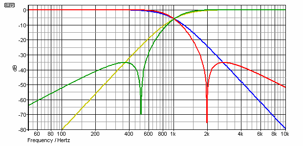
The frequency response is shown below, and this is an almost perfect match to that shown in the BSS brochure. The frequency and amplitude scales are different (from the BSS graph), but the response is virtually identical. For comparison, the response of a Linkwitz-Riley filter is also shown. Not shown is the summed response, which is completely flat for both filters.

Figure 1 - NTM and L-R Crossovers Compared
The NTM crossover response is shown in green (high pass) and red (low pass), while the L-R equivalent is in a yellowish colour (high pass) and blue (low pass). It is undeniable that at one octave either side of the 1kHz crossover frequency shown, the response is better than 60dB down from the nominal output level. Looking at the L-R filter by comparison, at the same frequency it is only 30dB down. Unfortunately, the response of an elliptical filter rises again after the notch - again readily visible.
About ½ an octave above and below each notch, response is back up to about -36dB (equal to the L-R), and beyond that performance is inferior to the Linkwitz-Riley implementation. Ultimate rolloff for a fourth order elliptical filter is 12dB/octave. None of this is shabby by any means, but it does show that some of the descriptions used in advertising literature are rather misleading once the full details are known.

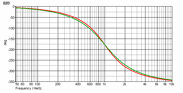
Figure 2 - NTM and L-R Crossover Phase Response
There is not much phase difference between the two - they are (for all intents and purposes) the same in this respect. The red graph is the NTM filter, and the L-R is shown in green. Both filters have a 360 degree shift across the band, with the NTM filter being very slightly worse in this respect than the L-R filter.
In real terms, the difference is marginal only, and should not be audible. Despite the apparently radical phase shift, both drivers remain in phase with both filter types, and the phase shift in itself is normally inaudible (despite some claims to the contrary). While there are circumstances that can make phase shift audible, such a discussion is outside the scope of this article.
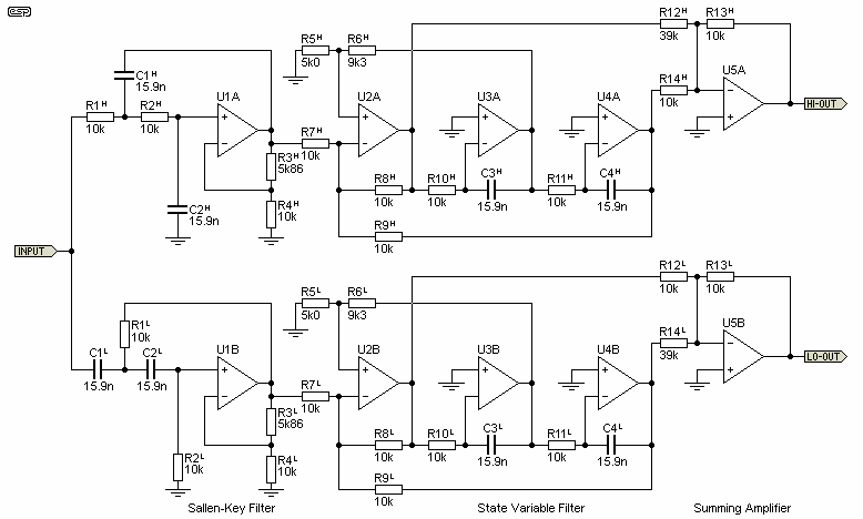
Please note that the diagram shown below is taken directly from my simulation. It is not (and does not purport to be) the actual circuit of an NTM filter, but I strongly suspect that it will be rather similar. I have not seen the actual circuit, nor has it been traced from an actual working NTM crossover, so the 'real thing' could possibly be completely different.
The general principle of an elliptical filter is/should be pretty well known in engineering circles where filters are used extensively, and it consists of a conventional second order filter, followed by a second order state-variable filter.
The high pass and low pass outputs of each state-variable filter are summed to give the response shown above. The values shown are those used in the simulation. The hardest part of implementing a filter such as this is component 'sensitivity' - the requirement for close tolerance is increased compared to (say) a more conventional Linkwitz-Riley crossover network.

Figure 3 - Elliptical Filter Crossover Network Schematic
As you can see, the capacitor values are non-standard, but that was done to obtain a nominal 1kHz crossover frequency. This was selected because it is a defacto standard when showing general filter responses. It is not a useful crossover frequency for real use. Phase response is shown above, and is almost identical for both filters (NTM and L-R), and the ripple in the summed outputs is less than 0.2dB.
The circuit itself is relatively conventional for this filter type, but there are some important variations and points that need some explanation. The first stage (around U1) is what is known as an 'equal component value' Sallen-Key filter. Unlike the standard circuit such as that shown in P09, the Q of the circuit is determined by the gain of the opamp, rather than the filter component values. This allows the circuit to use the same capacitor values as the next stage.
The second filter is a state variable type, using U2, 3 and 4. The filter frequency is set by R10, R11, C3 and C4, and the Q is adjusted by R6. The Q needs to be somewhat higher than for a standard filter, because the summing amplifier (U5) adds a selected amount of (out of phase) high pass to the low pass filter (and vice versa). This creates the notch, and R12 determines the notch frequency.
For such a complex filter, it is remarkably tolerant to component variations, but predictably less so than a fourth order L-R filter of the type used for Project 09.
In case you were wondering, the circuit shown will work, but the frequency determining components will have to be changed to get the frequencies needed rather than the 1kHz shown. In answer to the question (which will get asked at some stage) "How do I change the frequency?", the answer is that you will have to figure that out for yourself. This is not (and is definitely not intended to be) a construction project ... it is an explanation of how the circuit works. No more, no less.
This article has hopefully removed some of the mystery behind the NTM crossover network, and shows what can be achieved using some lateral thinking. The rise in amplitude beyond the notch is rather unfortunate, but at -35dB represents an effective power that is over 3,000 times (3,162 to be exact) less than the maximum applied.
This means that for an applied 100W input power to a loudspeaker driver (via the crossover of course), the worst case out-of-band power level (> 1 octave) is only 31mW. This is further attenuated at a rate of 12dB/octave. At 3 octaves from the crossover frequency, (125Hz and 3kHz), the out-of-band power level is down by 48dB - 1.58mW for 100W input. This is insignificant.
By comparison, the L-R crossover is at -24dB one octave from crossover frequency (400mW), at two octaves it is at -48dB (as above - 1.58mW), and at three octaves it has an output of -72dB (6.3uW) - again, assuming 100W input power to the loudspeaker drivers. For all practical purposes, this is also insignificant.
The end result is that loudspeaker drivers can be pushed closer to their limits, because the out-of-band power is reduced. There is usually no good reason to push any driver that hard in a domestic system, but it can result in a useful improvement for high powered professional applications.
The greatest benefit is obtained at between ½ octave to 1 octave either side of the crossover frequency, with an improvement of around 10dB at the ½ octave frequency, increasing dramatically to the 1 octave point. This represents a significant improvement, but only where drivers are being pushed to their limits. In a domestic system, all drivers will (or should) generally have sufficient 'spare' bandwidth to be able to cope with the out-of-band power levels with no stress whatsoever.
Overall, the circuit is very impressive though - not so much because of the cunning application of elliptical filters, but more because of a complete re-think about the way such filters are normally designed and tuned. The Neville Thiele Method™ certainly delivers a very worthwhile improvement in overall crossover network performance.
Please note that the NTM crossover network is patented, so commercial use of the information presented here will infringe patent rights and may result in a law suit or other potentially expensive unpleasantness.
Also, as pointed out above, the circuit shown is not taken from any literature, service manual, physical crossover or anywhere else. It is my interpretation of a circuit that will achieve the same result as an NTM crossover produced by a licensed manufacturer.
Based on extensive searches, it would appear that this is the first published circuit (for general viewing) that achieves the results claimed for the NTM crossover network. This page has been seen by Precision Audio, and a couple of minor changes made at their request. I have provided them with an undertaking that I will not (under any circumstances) [my emphasis] provide tuning formulae or any additional information that would allow patent infringement.
Note that the patent for this network has expired in Australia, but is still active in the US and elsewhere worldwide (expected expiry date on or around 22 March 2021). However, to retain good faith it will not be published as a project, although I may add some more information here after the worldwide patents have expired. The schematic shown above is not the same as that used in the patent documents, and performance is not quite as good. However, it is still a workable circuit and performs as shown in the graphs.
 Main Index
 Articles Index