
|
|
| Elliott Sound Products | Isolation Transformers |
 Main Index
Articles Index
Main Index
Articles Index
Before I start, I must point out that most common transformers provide isolation. The transformer used for a power amp or preamp will always provide galvanic isolation between hazardous voltage (the mains) and the lower voltages needed by most circuitry. Galvanic isolation simply means that there is no electrical connection between the mains and secondary windings, and power transfer is provided by a magnetic field. Other forms of galvanic isolation include optocouplers, pulse (small, high frequency) transformers and capacitive couplers (using a very low capacitance). While these provide isolation, they are not the subject of this article. All galvanic isolation products will show an open circuit between the mains and secondary (or input and output) when measured with an ohm meter or insulation tester.

WARNING : The information herein describes circuitry that is not isolated from the mains and must never be used as a matter of course. All circuitry must be considered to operate at the full mains potential, and must be insulated accordingly. No part of the isolated circuit should be considered 'safe' when a test point is earthed via an oscilloscope probe or other earthed connection. Do not work on the connected circuitry while power is applied unless you know exactly what you are doing, as death or serious injury may result. The use of an isolation transformer does not make circuitry safe, it allows you to make connections that would otherwise be lethal (to you or your test gear!).
This article is based on the use of a 1:1 mains transformer (120V or 230V), used to isolate the mains input so there is no neutral (earthed) conductor on the secondary side. These are commonly used as a 'safety' measure, but as described here, this is often inappropriate and can be dangerous. It has long been believed by many people that using an isolating transformer on the test bench is a good safety measure, and will somehow protect the service tech from harm. In reality, for most products, this is false. If you always use an isolation transformer, it can let dangerously faulty equipment pass undetected.
There are cases where an isolation transformer is absolutely essential. It's still very common, and circuitry connected directly to the mains is dangerous to work on. An isolating transformer is essential if you need to work on the electronics. In the 'old' days when so-called 'hot chassis' equipment was popular (it was cheaper to build), you couldn't work on the gear without an isolation transformer. These products were common, especially in the US, but also in Australia and elsewhere. TV sets were the most likely to have a hot chassis, but there were also radio receivers that used the technique.
The idea was to dispense with the heavy and expensive mains transformer, and run everything from the rectified mains. Valve heaters were run in series, and there was a complete range of valves that had widely differing heater voltages, but they all drew the same current so they could be run in series.
The most common requirement now is switchmode power supplies, but most aren't designed to be repaired. For those that can be fixed, you definitely need an isolation transformer, but it should be left disconnected and out of circuit for any other gear you work on. While many people think that isolated mains are 'safer', it's an illusion (and a dangerous one!).
The safest way to power mains operated equipment (but where you don't need to work on live mains) is from the normal mains via a safety switch. These go by many names, such as core balance relay, RCD (residual current device), earth leakage circuit breaker (ELCB), ground fault (circuit) interrupter, or just plain old 'safety switch'. A full explanation of how these work is outside the scope of this article, but is easily found on-line via a web search. A brief and simplified description is provided below. Note that I will use the term 'safety switch' as a matter of course.
Of course there are situations where use of an isolation transformer is essential, with one being an unexpected requirement - testing portable safety switches. You may find that when you attempt to test a portable RCD, the main RCD at the switchboard operates either instead or as well as the one being tested. The way to fix this problem is to use an isolation transformer, but wired so that it creates a 'new' neutral and earth connection that is seen by the RCD being tested, but not by the RCD that protects the outlet being used. This is a specialised application, but is easy to do if you need it.
Note: The terms 'earth' and 'ground' are synonymous - in Australia and many other countries, we use the term 'earth' to mean 'ground', but in the US (and some other locales) the term 'ground' is used (almost) exclusively. There is no cause for confusion, as the two terms mean exactly the same thing in the context used in this article.
To be able to work on the hot chassis receivers, it is essential to use a 1:1 isolation transformer. Without it, it's impossible to use an oscilloscope, and simply touching the chassis could be lethal. These 'hot chassis' products have now all but vanished from the mainstream, but many pieces of vintage gear are still restored by hobbyists all over the world. Now, we have SMPS (switchmode power supplies). These (mostly) solve the isolation problem on the secondary side, but of course the SMPS primary circuitry itself is at mains potential. Also, be aware that some LED lighting power supplies are not isolated, so everything is at mains potential! This means that touching the wiring to the LED panel may be dangerous, but fortunately, such light fittings are generally fully enclosed to prevent contact.
If you happen to be servicing a switchmode supply or other mains powered (transformerless) products such as LED lighting fittings or dimmers, then you will need an isolation transformer for the same reasons that existed with hot chassis equipment. However, most are not serviceable, being tightly crammed with surface mount parts, and usually there's next to no chance that you can get the schematic. Most of the time, service of these is a case of total replacement. You can look for bulging electrolytic capacitors, burnt transistors or ICs and/or tracks blown off the board. It's not uncommon to have all three, and unless you are very resourceful, the supply/ dimmer (etc.) will be a write-off. In a few cases, replacing bad caps or a blown MOSFET might be enough to get it working again (if you're lucky).
For additional safety, use a Variac with the isolation transformer if you can. Many switchmode supplies are designed to operate from 90-260V, so using the lowest voltage possible for the SMPS to work means that some of the voltages you are exposed to are lower, and have a lower risk factor. This doesn't always work of course - some SMPS only work over a limited voltage range. Others generate 400V DC or more before it's switched to the transformer (active power factor correction) and the voltage is the same regardless of input voltage within its operating range.
For any other type of service (where the supply is working but other parts of the circuit are not), you should never even contemplate using an isolation transformer. It is wrongly believed that using one is somehow 'safer', but this claim is simply false. Most workshops and houses are fitted with safety switches, and if your workbench doesn't have one, go out and buy one to protect yourself. Preferably right now!
With a safety switch, if you make contact with live parts, the switch operates and turns off the power before you are killed. They rely on the fact that current normally flows between active (line) and neutral, and the current in each lead should always be the same. If you contact a live part of the circuit, some current flows through you to earth/ ground. This unbalances the current (so the current in the active and neutral conductors is different), the switch detects the imbalance, and turns off the power.
The idea of an isolation transformer is that you can touch any ONE part of the circuit and not be harmed, but if you contact more than one point, you may get an electric shock. The safety switch will not operate no matter what is happening to you - you could easily be dead for hours, with the power still on. If you think that's an unpleasant thought, you would probably be right.
Without isolation, you know exactly what is dangerous at all times. It's quite apparent that you can't touch anything that's at mains potential, and the sensible technician will treat the neutral as a live conductor. This is how it's treated in wiring rules worldwide. Once the mains is isolated, everything is 'safe' until it's not. That's not as silly as it might sound at first - any connection you make with test equipment (oscilloscope, signal generator, etc.) makes everything except the earthed point unsafe. It will not always be apparent which parts you can touch, and which parts you can't.
Figure 1 - Mains With & Without Isolation Transformer
In the drawing, it's obvious that the normal mains provides you with an active (live) wire, a neutral wire that's (nominally) at earth potential, and a safety earth that connects to chassis and/ or exposed metal surfaces. The neutral may be earthed at the switchboard (MEN system) or at the distribution transformer. All countries earth the neutral conductor somewhere, and it's uncommon to measure more than a couple of volts between neutral and earth/ ground.
The only time you will get an electric shock is if you make contact with the live conductor - everything else is 'safe'. Should that happen, the safety switch operates and saves you from further harm. With the transformer, you now have two 'live' conductors. Touching either one won't cause harm, but if you get across both you are in trouble. Should the equipment have a mains fault (one or the other mains lead shorted or otherwise connected to chassis via capacitance or resistance - shown with dashed lines), you won't know about it until you touch the wrong thing. Trouble is, you don't even know that there is a 'wrong thing', or where it's hiding.
The instant you connect an oscilloscope probe to a 'common' part of the isolated circuitry, everything else becomes dangerous, and if you touch it, AC will flow through you to earth/ ground via the oscilloscope. It is an extraordinarily foolish move to remove the earth connection of the scope, as that means the oscilloscope itself can become live. I've seen it done, and the risk is extreme to the service tech and (perhaps more importantly) to anyone else who happens by. When people see metal enclosures, it's normally assumed that touching them won't kill or injure them. A floating scope can easily become lethal, and it's one of the most dangerous practices I've ever seen.
One thing that an isolation transformer absolutely does do is provide a false sense of security/ safety. A service tech who routinely uses one will assume that it's perfectly safe to handle any part of the circuit. This is only partially true at best, but if there's a wiring fault then it can easily become a serious hazard to your longevity. Most of the time, nothing will happen, but if that same tech uses someone else's workbench that is not fitted with an isolation tranny, then s/he is at serious risk.
Under no circumstances should more than one appliance be operated via the same isolation transformer. If one has a mains fault, it can easily place the user in great danger. This is why the mains has a dedicated active and neutral, with the neutral conductor earthed either at the distribution transformer, or at each main switchboard. The latter is used in Australia, and is called the 'MEN' (multiple earth neutral) system. Isolating transformers are sometimes used in hospital operating theatres for safety, but they are fitted with monitoring systems that continuously verifies that the impedance between both connectors and earth remain high [ 1 ]. Test bench units don't have that, so great care is necessary.
Despite the fact that some people assume that they won't be subjected to electric shock when using an isolation transformer, it remains quite possible. If you are even a little bit careless or complacent, possible becomes probable, and it's somewhat unexpected when (not if) it happens. As already noted, the safety switch won't operate when a transformer is in the way. You can use a secondary safety switch of course, but in order for it to work, it must have an earth/ ground reference - just like the mains. This makes it completely pointless, because you have simply created exactly the same circuit, but with a transformer in between. The power company already has plenty of those, and they don't help either.
What many people really fail to recognise is that if the equipment being serviced has an earth fault (active or neutral shorted to chassis for example), it will not show up if an isolation transformer is used. The chassis will be at some potential determined by the nature of the fault, but because of the isolation, the service tech won't see anything amiss. It's entirely possible that the service tech could get a severe electric shock as a result, because the chassis (assumed to be 'safe') could be live with respect to other circuitry that is normally safe.
When equipment is serviced for (especially) non-technical customers, it's vitally important that it's tested while connected the same way as the customer uses it. The customer won't be using an isolation transformer (at least in 99.99% of cases), so the equipment should not be tested using one. Any equipment that is intended to be earthed (whether through the earth pin on the mains lead or by any other means) should be earthed while it's being serviced. This is the only way you know that there is (or is not) an earth fault. Yes, you can test with a multimeter, but that's not a satisfactory substitute. It's also far too easy to forget that earth continuity has to be checked if an isolation transformer is always in circuit.
A perfect example of how a short from active (or neutral) to chassis can occur is the so-called 'death cap' installed in many early US guitar amplifiers. These caps are usually 630V DC types, which are completely unsuitable for connection between 230V mains and chassis, and they are called 'death caps' for a very good reason - they can and do short out, and having done so they may or may not explode. Exploding is actually good, because it takes them out of circuit permanently, but the mains wiring may not be safe afterwards.
Look at the schematic for a 1960s era Fender to see an example (or look at the example below). There is usually (but not always) a switch that allows the hapless user to switch the cap between active or neutral to chassis, and the original idea was to select the switch position that gave the least hum - this will nearly always be when the neutral is connected to chassis via the capacitor and switch. Using any capacitor of more than a few nanofarads is now totally illegal everywhere, and even that small value must be a Y-Class (fail-safe) type.
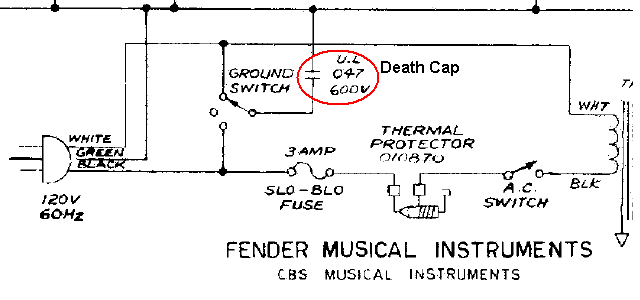
Figure 2 - Fender Death Cap (100W Bassman)
Note that the circuit is quite deliberately not converted to the style that I normally use so its origin is clear. I must also state that the export version of the same amp does not have the death cap. However, that's of little consequence today, since vintage amps are routinely sold all over the world, regardless of origin or intended market. The UL (Underwriters Laboratory) listing for the cap means that it has been type tested for safety, but they still explode, even in the US with only 120V mains. Note that the partial schematic shows a 3-pin (earthed/ grounded) mains lead, but a great many earlier amps used only a 2-pin plug and mains lead. This type of equipment (technically known as 'Class-0') is no longer permitted anywhere in the world.
Fender was by no means alone of course, and some other manufacturers didn't even bother to use a UL listed capacitor! Some included the death cap in their export models - usually a 630V DC 'orange drop' or similar. These will fail with 230V mains! Feel free to look up 'death capacitor', and be very aware that some commentators have no idea what they are doing or talking about, and their opinions should be discounted. There's even a video where the person clearly shows he has no idea (although he thinks he does).
The death cap has not been used in most US equipment since the mandatory introduction of earthed mains plugs and receptacles, but some manufacturers persisted regardless for a while. It's now almost certain that new gear will not have it fitted, but vintage guitar amps don't get thrown away - ever! As a result, you will still find death caps in old amps, and it will take some time before they are all gone. As long as the death cap remains in circuit there is an ever-present risk of a short from mains to chassis. The death cap should be removed - always - no exceptions! A user who insists on 100% authenticity for a vintage amp will be unable to enjoy it if it kills him or her, and this point needs to be emphasised as you remove the cap completely.
If you're using an isolation transformer to run all your tests, you may miss a mains to chassis fault altogether! This is clearly a case where mains isolation is not just 'not required', it should not be used at all.
The 'death cap' is only one of many possibilities that can lead to a chassis becoming live, and is mentioned here because it is one of the more common issues, especially when a US 'domestic' vintage amp is exported and used at 230V. perhaps with a replacement transformer, or an external step-down transformer. There are countless ways to get faults of this nature, and the point is that if you use an isolation transformer and don't test with 'normal' mains and an earthed chassis, you may never know that it's waiting to kill someone.
Something that needs to be mentioned is the isolation transformer itself. Most will NOT be made to medical standards, and the quality of their insulation between windings may only be to 'basic' specifications. In other words, unless specified as double insulated, they cannot be classified as a 'safety' transformer. If you buy a 'medical grade' unit intended for use in an operating theatre or ICU (intensive care unit), it will be fully specified and tested to ensure it meets the highest standards.
Most will not meet this level of protection. This doesn't mean they are 'unsafe' as such, but risking your life on the use of a 'basic' insulation rating may not be a very good idea. Unless you search hard, you are unlikely to be able to find the insulation rating for isolation transformers, because not all are designed specifically for safety. They may be used simply to eliminate any DC component from the mains, or to break an earth loop.
Transformers are classified according to their insulation rating, but the information is not always easy to find. The following table shows the classes that are used in the US, and there are similar classes elsewhere (but they may use different terminology). Although easy enough to find, you have to know what to look for. Most general purpose transformers will probably fail to specify their insulation class, so assume they will be at the lower end of the range (lower maximum temperature). This can be important if your isolation transformer is subjected to an accidental (or deliberate) overload.
| Insulation Rating | Insulation Class | Avg Winding Temp Rise | Hot Spot Temp Rise | Max Winding Temp |
| Class 105 | A | 55° C | 65° C | 105° C |
| Class 150 or 130 | B | 80° C | 110° C | 150° C |
| Class 180 | F | 115° C | 145° C | 180° C |
| Class 200 | N | 130° C | 160° C | 200° C |
| Class 220 | H | 150° C | 180° C | 220° C |
| Note: the maximum acceptable temperature rise based on an average ambient of 30°C during any 24 hour period and a maximum ambient of 40°C at any time. | ||||
You can use a pair of transformers wired together to create a very effective (and safer than average) isolation transformer. You need two identical transformers, ideally with a fairly high secondary voltage. Around 50V or more at the secondary will usually be ok. They are wired as shown below, with the two joined by their secondary windings so the second transformer is a step up transformer from 50V to 230V (or 120V). Because such a transformer is designed to ensure safety, using two means that you have double insulation between the mains and the isolated output. Maximum current is around 1 amp at 230V or 2A at 120V - it's not very high, but more than sufficient for most testing with light loading. The other advantage is that for many hobbyists, it will be somewhere between free and cheap if suitable transformers are available.

Figure 3 - DIY Isolation Transformer
This arrangement is less efficient than a 'real' isolation transformer, but because there are two separate sets of insulation (one on each transformer) it has better isolation between the mains and whatever you are working on. The output voltage will always be a bit less than the input, magnetising current is a lot greater than a single transformer, but it lets you use parts that you can probably get for much less than it will cost for a dedicated isolation transformer. Because you won't use it unless you absolutely have to, the inefficiency and lower voltage won't be an issue.
A primary fuse is essential, and you can add another fuse on the secondary if you like. A neon panel lamp is a good indicator to show that the power is on. I've shown a pair of 200VA transformers, but larger ones will also work. If possible, I suggest that you use E-I type transformers rather than toroidals. They are slightly less efficient, but are more tolerant of the fairly high magnetising current drawn by the second transformer, which is used in reverse to get the required 230V (or 120V with a pair of 120V transformers). With 230V input, the output will be somewhat less. My unit which is built as shown gives an output of ~220V with 230V input.
None of the above means that an isolation tranny cannot (or should not) be used of course. There are (and always will be) perfectly good reasons to use one. I have one that's always at the ready, but it is used only when I need to take measurements of otherwise dangerous voltages on the mains side of equipment. And yes, I have been zapped while using it, and the safety switch did not operate! So much for it being 'safe'. I used it because I needed to use the oscilloscope to see the switchmode waveform, so part of the circuit was earthed. The remainder was waiting to try to kill me.
Use of an isolation transformer should be limited only to equipment (or test procedures) where it's essential. The rest of the time, equipment should always be connected to the mains in the same way that it is when being used normally. While this means that there will be some parts at hazardous (mains) voltages, these are generally inaccessible in a lot of gear. The exception is switchmode supplies of course, but it's common for them to be treated as exchange items only, and most are not designed to allow repairs.
When you do need to use isolation, be extremely careful and ever mindful of the risks and warnings described here.
Your workbench must be fitted with a safety switch, and it should be checked regularly to ensure it's working properly. Most have a 'self test' button, which deliberately unbalances the mains by just enough to cause the switch to trip. If it fails the test, replace it immediately. This is by far the safest way to work on mains powered equipment, but that doesn't mean that you can be complacent. It is still possible to get yourself across the active and neutral conductors in some cases, and if you are wearing rubber-soled shoes there is no connection back to earth, and the safety switch won't operate. This is not a common hazard, but it does exist, and an isolation transformer makes absolutely no difference!
The instant you connect your oscilloscope or other earthed test equipment to a point in the circuit, everything else in the circuit is waiting to try to kill you. Your safety switch won't operate if you accidentally touch a live part of the circuit while using an isolation transformer, and you must be aware of this at all times. It's simply not possible to be too careful, and likewise it's not possible to emphasise this too heavily.
Working on mains powered gear is always hazardous, and valve (tube) amps are particularly nasty if you contact the main high tension supply. 500V DC is very unpleasant, but neither the safety switch nor an isolation transformer makes it any safer. This is because the HT section of the equipment is not (galvanically) connected to the mains, so anything that you do to the incoming mains is immaterial.
Most of the time, and contrary to common 'wisdom', you will actually be far safer without an isolation transformer. The safety switch is your best friend. Experience counts for very little, and electricity really doesn't care if you know all its little secrets or not. If you get between active and neutral, you will receive an electric shock. If you are lucky, it won't kill you. An isolation transformer doesn't change that one iota! 120V mains is much safer than 230V mains, but people die from contact with both at depressingly regular intervals.
Please make sure that you aren't one of them!
In the US construction workplace (and this appears to be common elsewhere as well), electrocution is the second or third most common cause of death, exceeded only by falls (or dropped objects) [ 3 ]. The ranking for electrocution is most likely being reduced somewhat by the adoption of battery powered tools for many applications. If you look up the relevant statistics for the country where you live, you'll find that they are similar in most places. Unfortunately, it can be difficult to find the stats for other industries, and 'DIY audio' information will probably be next to impossible to track down.
Main Index
Articles Index