
|
| Elliott Sound Products | Subtractive Crossover Networks |
 Main Index
 Articles Index
A class of electronic crossover is variously described as a 'derived' or 'subtractive' filter is hailed by some users as the ideal. They have (apparently) perfect transient response, in that the summed output is not only flat, but a squarewave is also passed intact. This implies that they are the 'Holy Grail' of electronic crossover networks. Almost by definition, no other crossover network should even be considered.
So, are they any good? Why aren't they used everywhere?
These questions are best answered by a full examination of the network, so that all the facts are available.
The general idea of the subtractive crossover is quite simple. If we have a filter, and subtract the filtered signal from the input, the result is a filter with the opposite effect (i.e. a low pass filter is 'derived' from a high pass filter and vice versa). Because of the subtraction process, the result must be perfectly in phase, and the sum must (by definition) be flat response.
There have been many variations on the general theme, some of which are claimed to provide better performance than others. Subtractive filters have been discussed in Elektor magazine [ 1 ] and some I have seen are quite complex. While the added complexities may suit a particular arrangement of specific loudspeakers, they generally don't add anything that changes the overall performance.

Figure 1 - Block Diagram of a Derived (Subtractive) Filter
While all circuits shown in this article are configured as shown in Figure 1, the filter itself can be a low pass section. No other changes are needed, but this connection may give rise to performance limitations that at the very least must be classified as undesirable (see below for more information).
In the circuit diagrams below, all buffers are unity gain, and all circuits are driven from a low impedance (voltage) source. This is a requirement for all filters, so the input buffer is not shown for clarity. The voltage source shown is an ideal voltage source - zero ohms output impedance.
Likewise, for clarity, the power supplies are not shown. All the results below are from the SIMetrix simulator, and while somewhat idealised, are representative of reality with any reasonable opamp in a real world circuit - especially within the audio band.
Within this article and for the simulations used to get the graphs shown, the same values were used for filter tuning, regardless of the filter order. While this does change the crossover frequency, as you will see it is actually of little consequence.
There is another method for creating a subtractive filter that cancels out the rather annoying fact that the derived section otherwise always has a 6dB/ octave slope. By adding phase shift networks, the derived filter can have the same slope as the main filter. However, as soon as you do that you eliminate the main (supposed) benefit of a subtractive network - it will not longer pass a squarewave without changing the wave shape! In addition, the tolerance of the phase shift networks (all-pass filters) is such that very good component matching is needed or the summed response will not be flat. An example is shown in Section 6.
Note: In the following circuits, I used the same resistance and capacitance for each filter. This means that the crossover frequency changes, depending on the network. This is of no consequence, as the idea is to show the trend rather than complete working designs. It works out that with the values used, the 6dB/ octave circuit crosses over at 1kHz, the 12dB/ octave at 882Hz and the 24dB/ octave at 708Hz. All frequencies are nominal except for the 6dB filter and the reference 24dB/ octave Linkwitz-Riley circuit, as they are the only circuits that are well defined. Subtractive crossovers are somewhat 'undefined' because of the overlap region and frequency peak. The frequency is based on the output of the filter, not the 'derived' output.
While there is little point looking at a first order (6dB/ octave) network, it is the simplest to examine, and this will make it easier to follow the more complex filters. A first order crossover is already 'phase perfect', so making a subtractive version should give an identical result.
As shown below, this is the case. The only advantage of the subtractive method is that only one reactive element (the capacitor) is used, and this is highly debatable as an 'advantage'. This is especially true with the increase of overall complexity of the circuit.

Figure 2 - First Order Subtractive Vs. 'Conventional' Crossover Networks
Figure 2 shows the schematic of the subtractive filter, and for comparative purposes, a conventional filter is also shown. A conventional high pass first order filter is used, although a low pass filter can also be used and gives identical overall results. The subtraction circuit is simply a common balanced amplifier, which only amplifies the difference between its two inputs. The frequency and phase responses are shown below, and they are identical to a 'normal' 6dB filter response. The summed output is flat, having no peaks or dips at the crossover frequency. Since a straight line is hardly inspiring to look at, this has not been included for this or any of the graphs that follow.

Figure 3 - First Order Amplitude Response
The amplitude response is as one would expect, and requires little or no further comment. As stated above, this is identical to a conventional first order filter response.

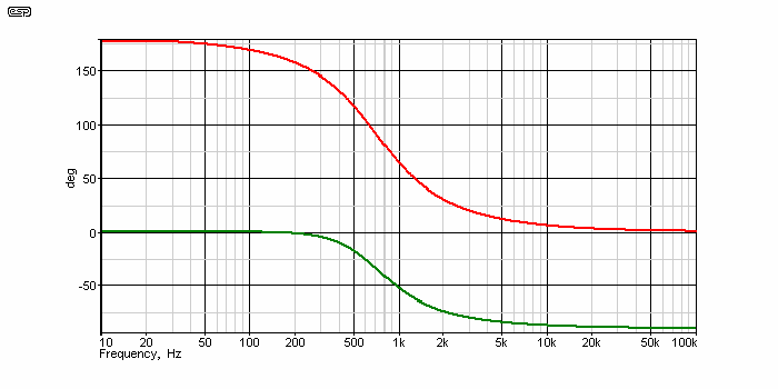
Figure 4 - First Order Phase Response
Phase response again shows the normal behaviour for a first order filter. In all cases in this article, the red curve is for the high pass filter, and the green curve is the low pass. As noted earlier, there is no point using the subtractive method for a 6dB/ octave crossover - the above is by way of example only.
When we look at second and higher orders, we start to see real difference between the subtractive filter and other more conventional crossover networks. Figure 5 shows the schematic, and it must be admitted that it is a little simpler than a standard Linkwitz Riley filter (for example). While the difference in complexity is not great, the summed response is better, and unlike nearly all filter networks above first order, it is not only phase coherent, but the summed signal reproduces a perfect squarewave.
It is at this point that some people get excited - any filter that can pass a squarewave must be better than one that cannot, and in truth, virtually no conventional filter above first order can reconstruct a squarewave. The subtractive versions therefore must be better.
As we will see later on, this is not necessarily true, and the ability to reproduce a true squarewave is vastly overrated. Apart from anything else, we rarely listen to any audio signal that even approaches a squarewave, but there are other relevant factors that will wait until the conclusion of this article.

Figure 5 - Second Order Subtractive Crossover Network
Above, we see the schematic for a second order (12dB/ octave) derived crossover. A single second order Butterworth highpass section is used, with the difference amplifier subtracting the filter's response from the input signal. One would think that by doing this, the derived filter would match the rolloff characteristics of the filter, but this is thwarted by phase shift. It is phase shift that causes the derived rolloff slope to remain at 6dB/ octave, and although it is possible to include a phase shift network to equalise the slopes, this will no longer allow the filter to recreate a squarewave, and it will behave the same as any other filter network.
 |
In fact, various magazines (Elektor being one that I know of - thanks to a reader) have published projects that use a combination of a standard subtractive crossover
with a phase shift (all pass) network. This does equalise the rolloff slopes, but the network behaves in the same way as a conventional crossover network. These are covered
in section 6 below. These filters suffer from high sensitivity to component tolerance. The 'saving' is two capacitors, but you need more resistors and one additional opamp (not much of a saving). The circuit complexity is greater than a conventional filter because the repetition is replaced by a relatively complex phase shift network plus a summing amp. This makes it more likely that a mistake will be made while wiring the circuit. IMO there is absolutely no benefit, and it is far easier to build a conventional Sallen-Key (Linkwitz-Riley alignment) based filter network such as that shown in Project 09. |
Look carefully at the graph below ... as explained above, while the high pass section certainly rolls off at 12dB/ octave, the derived low pass section is indeed only 6dB/ octave. This is one of the greatest disadvantages of the subtractive crossover. The derived filter is always 6dB/ octave, regardless of the rolloff slope of the filter itself. (However, see note above.)

Figure 6 - Second Order Amplitude Response
Potentially of some concern is the peak in the low pass response, just before it starts to roll off. This can be reduced by reducing the Q of the filter. While it is not serious, the expectation is that the tweeter will have sufficient output at this frequency to cancel the acoustic peak, thus restoring flat response. As discussed in greater detail below, this may be wishful thinking.

Figure 7 - Second Order Phase Response
The phase response is shown above. It is seemingly impossible that two outputs with such frequency and phase responses could possibly be summed to a flat response, but they do, and this filter (just like the first order network) can pass a perfect squarewave when the outputs are summed. Likewise, the summed response is completely flat, with no peaks or dips.
It is rather unlikely that the acoustic outputs from the drivers will be able to match an electrical summing network, so it is less likely that the acoustic output will be flat. Electrical and acoustic summing are not the same thing, and although electrical summing is an effective way to find out the ideal response of the system, what happens in reality is likely to be altogether different.
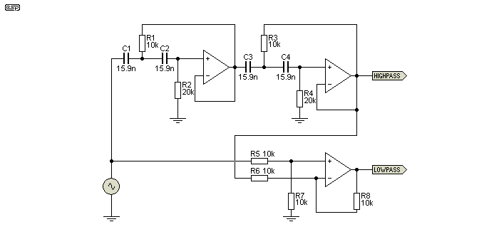
Finally, the circuit diagram below shows a derived 24dB/ octave (fourth order) network. Where this should offer the best response, in fact it is the worst of the three shown.

Figure 8 - Fourth Order Subtractive Crossover Network
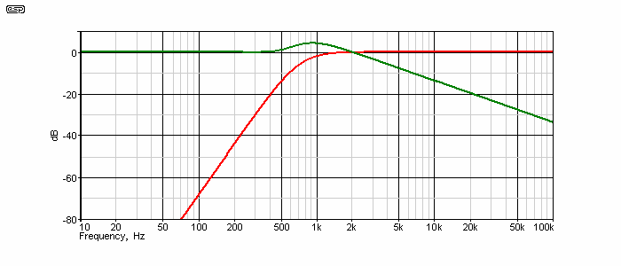
The amplitude response (below) shows that there is a substantial rise in the response of the low pass section (the derived part of the network). If (and that is a very big ask indeed) the drivers sum as flat as an electrical network, then there isn't much of a problem. It is highly unlikely that the drivers will be able to produce a flat response in reality.

Figure 9 - Fourth Order Amplitude Response
The response peak is 4.3dB, and that represents more than double (x 2.7 in fact) the power applied to the driver over that frequency band. The amount of frequency overlap is (IMO) completely unacceptable, and a system built using this crossover would have to use accurate time alignment. Great care would also be needed to ensure that the polar response of the drivers is very similar over at least 3 octaves across the crossover frequency. The high pass filter shown uses the Linkwitz-Riley alignment, because it has a relatively low Q. A more traditional Butterworth filter (Q = 0.707) increases the amplitude of the peak to over 5dB. To add insult to injury, it doesn't even reduce the overlap !

Figure 10 - Fourth Order Phase Response
The phase response also shows a peak, but this is of less consequence than the amplitude peak. Subtractive filters are usually not phase coherent. That is to say that the phase of the signal applied to each driver varies, and the two are not in phase across the crossover region. Unless the phase response of the drivers is very predictable (no phase shift from voicecoil inductance or resonances) the two signals can no longer sum flat - even electrically. Acoustic summing will be worse than electrical summing in all cases.
So that everything can be seen in the one article, I have included a schematic of a 24dB/ octave crossover, along with the amplitude and phase response. The first thing you will see is that there is actually little additional complexity. Rather than a complex circuit, it is simply repetitious. This is the simplest of the topologies that will give the desired overall response.

Figure 11 - Fourth Order L-R Filter Schematic
The high pass section is at the top, with the low pass section at the bottom. This is identical to the circuit used in Project 09, which has been a popular project from the time it was first published.

Figure 12 - L-R Amplitude Response
Amplitude response is exactly as we would expect. A nice steep rolloff for both sections, and a clearly defined crossover frequency. Because of the Linkwitz-Riley alignment, the summed output is completely flat (just like the subtractive filters), but without any of the associated problems of excessive overlap. No, it won't pass a squarewave without changing the wave shape, but the summed output still contains every frequency that made up the original squarewave, and testing by ear reveals that it is not always possible to positively identify the squarewave from the modified version. While there is almost always a difference, it's often below the threshold of audibility, and the nature of the difference has more to do with the loudspeakers than the crossover.
The only valid test with something like this is what I call the "walk out of the room" test. You listen to music, a squarewave or some other audio stimulus, then walk out of the room while an assistant either swaps out one network for the other - or not. When you return, you can then decide if there is a difference - or not. Naturally it's important that your assistant maintains a 'poker face' and provides no clue one way or the other. This is a hard test, and you might be surprised how many things you thought you could identify easily magically disappear when you use this method.

Figure 13 - L-R Phase Response
In case you wondered, no, I didn't leave out the high frequency phase response. It is simply overwritten by the low frequency graph - they are perfectly overlaid. That means that the two drivers remain in phase over the entire frequency range. This filter network relies on proper filtering, rather than hoping that the acoustic outputs of the drivers will complete the job that in reality is only half done by a subtractive filter.
There have been many subtractive/ derived crossover designs that use a phase shift network to make the filter's rolloff symmetrical. This approach certainly works, and gives results that are identical to a 'traditional' filter network. One small point that is rarely mentioned by the authors is component sensitivity - how much the response will deviate from the ideal when component tolerances cause the (mainly capacitor) values to vary a little.
A 'conventional' 4th order filter as shown above can be built using caps that are simply removed from the bag - they do not need to be selected. Measuring and selecting the caps gives a better result, but it's not essential. I've built a great many 24dB/ octave xover networks, and tests have shown that the deviation from ideal is well within normal expectations without having to select the parts. This is not the case with a phase corrected subtractive network! A small variation of one or more values can have a large effect on the overall response, because the final circuit relies on a perfect phase shift to derive the second output.
The circuits that have been published also use more parts overall than a Sallen-Key filter as shown in Project 09, with the majority requiring an additional opamp. This rather defeats the whole purpose, which is to make a crossover network that's less complex and allegedly has 'better' performance. It doesn't happen.

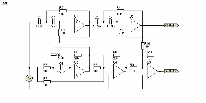
Figure 14 - Phase Corrected Subtractive Crossover
The circuit shown above is fairly typical of a phase corrected subtractive/ derived network. Several versions (virtually identical) have been published by several authors, and it's hard to see why anyone would bother. The necessary phase shift is created by the bandpass filter based on U3, and the summing network (U4) creates an all-pass filter (i.e. phase shift only). Its tuned frequency must exactly equal the -6dB frequency of the main filter network (U1, U2), 707Hz with the values shown. This matches the Figure 11 circuit, which is tuned to the same frequency.
There are more parts overall, an extra opamp, and it has identical frequency and phase response to the circuit shown in Figure 11 (if everything is exact). Some alternatives use a conventional (Sallen-Key) low-pass filter, and derive the high pass. The net result is still the same - greater complexity for no net benefit. There's no symmetry, the circuit is harder to build, and there are quite obviously no advantages.
There is clearly nothing to be gained by using more parts in a circuit that has far greater component sensitivity to produce a circuit that (if all goes well) simply mimics the results obtained from a simple 24dB/ octave high and low pass filter network. The best that can be said for this approach is that it's a flawed concept. At worst, it's just a waste of components.
Just in case you might imagine that the version shown in Figure 14 can pass a squarewave - wrong! Because it has identical frequency and phase response to the standard 24dB/ octave filter, it follows that overall characteristics must also be the same. With any piece of electronics, the frequency and phase response determine what it will do to the incoming signal. If two circuits (however different they may be) have the same response in the frequency domain, their effect on the signal in the time domain must be the same.
If you have guessed by now that I really don't like this approach, then you'd be 100% correct. 
The first - and possibly the most important - thing that must be understood is that electrical and acoustical summing are not the same thing. Just because a crossover network sums flat electrically, this does not imply that it must also sum flat acoustically. With subtractive crossovers, the very worst scenario is presented to the drivers, where there is considerable frequency overlap between the adjacent loudspeaker drivers, and unless they have identical polar response over the entire overlap region (and at least an octave either side), the combined acoustic output will be anything but flat. This seems to have been missed by many of the proponents of these filters.
Unlike conventional filters, where the higher the order sections have less overlap than low order, the subtractive networks present the opposite case. The derived section using a 24dB/ octave high pass section has the greatest overlap, and we can see from the above that the 6dB network is actually the best in this respect. Let us simply say that this is less than desirable (note careful use of understatement).
The next issue is the derived filter section's rolloff slope - 6dB/ octave. All the circuits above derived the low pass section, because that gives the greatest protection for tweeters (and midrange) drivers against excessive excursion. However, the midrange (or mid-bass) driver gets a significant boost at the highest frequency it is expected to handle, and this can lead to distortion due to cone breakup. Adding a phase shift network with an additional filter can make the slopes symmetrical, but the resulting circuit has high component sensitivity and uses more parts than an equivalent circuit using 'conventional' filter networks.
Quite a few published circuits over the years have derived the high pass section, and this places extreme demands on the drivers because of the power delivered below the crossover frequency. In addition, there is the peak at the very frequency where it is least desirable - at the lowest frequency the driver is meant to handle. It gets additional power at that frequency, increasing excursion and hence intermodulation distortion. If used for a tweeter, failure is likely because it gets too much power at frequencies it can't handle properly.
Speaking of crossover frequency, it is almost impossible to predict exactly where it is. It is obvious in the first order example, but as the filter order is increased, so too is the overlap region. One might want to use the -3dB frequency of the actual filter as a guide, but that's all it really is - a guide.
So, it should now be obvious that subtractive crossovers are most certainly not the 'Holy Grail', and in my opinion are virtually useless. Increased overlap at crossover may cause excessive beaming because the drivers are working as a mini-array, poor rolloff slope of the derived filter section can allow cone breakup (or if reversed, will probably cause excessive intermodulation), all because they can reproduce a squarewave. I think not.
The phase shifts caused by conventional crossover networks may seem extreme, but they are generally inaudible. Provided the phase of each driver is controlled and maintained (such as with a Linkwitz-Riley crossover), there are no audible effects. While phase anomalies may be audible if two different speaker systems are operated alongside each other, this is not a problem for home audio systems. The subtractive crossover network still has overall phase shift between drivers, so it doesn't solve that particular problem anyway.
Early in my exploits into electronics I did experiment with the idea, and have done so since as well. The measured results match the simulations pretty much exactly. While there is no doubt that the end result can be acceptable in a non-demanding application and at relatively low power levels, it's simply not good enough for a high grade system. I'd be happy enough to use a subtractive crossover for a background music system if that were the only option (although I'm unsure how that could come about  ), but it only takes a bit more effort to do the job properly. For the sake of a few more parts (or fewer parts if a phase shift network is included), you can have a 24dB/ octave filter that works properly.
So, if anyone was ever mildly curious, now you know why I have not (and will not) publish a project based on what I consider to be a seriously flawed design.
 Main Index
 Articles Index