
|
|
| Elliott Sound Products | Capacitor Characteristics |
 Main Index
Articles Index Main Index
Articles Index
|
It's often said that capacitors provide 'energy storage', but in reality, many used in audio circuits do nothing of the kind. Energy storage is certainly true for caps used in power supplies or to bypass the supply rails of power amps or opamps (for example), but caps that are used for coupling a signal and blocking DC (or simply as a safety measure should DC ever become present) perform no 'energy storage' at all, other than accidentally. The AC presented to one side of the cap is coupled through to the other side, and if the cap is large enough (compared to frequency and circuit resistance), it will never have any appreciable voltage across it. With no voltage, there is no stored energy. There will always be a tiny voltage present, but it's generally small enough to be ignored in an analysis.
In the light of this simple fact, it's very hard to know why such a great deal has been made of the 'sound' of capacitors. In most cases, these debates are centred on coupling caps, which (as noted above) generally have very little signal voltage across them. Dielectric losses (dissipation factor, dielectric absorption) feature heavily, with some fairly outrageous claims made as to the importance of these losses in amplifiers and other audio equipment.
Signal capacitors (as opposed to power supply 'storage' caps) work their hardest when used in filter circuits. This applies for active and passive filters, but caps used in passive loudspeaker crossover networks have to carry high current and often (relatively) high AC voltages as well. These need to be rated accordingly, and although there are bipolar (aka non-polarised) electrolytic caps sold for the purpose, IMO they are suited only for systems where fidelity is not a major concern. It's generally accepted that polypropylene is the optimum dielectric for this (and similar) applications, but for lower powered systems polyester is usually quite alright. Electrolytic capacitors (whether polarised or not) change their value over time, and are simply not suitable for high fidelity systems. In active filters (typically opamp based), the caps generally have very low current (a couple of milliamps at most) and low voltages. There is no need for 'special' caps in this application, but they still should be metallised film types (not high 'K' ceramics - ever!).
There are sites on the Net showing that different caps have different properties, and this is often used a 'proof' by many people that the differences are audible. There are sites that seem to have impeccable credentials, but have managed to create nothing but FUD (fear, uncertainty & doubt) with wild claims of irreparable damage to the signal by using the 'wrong' kind of cap ... even as a supply bypass (yes, it's true - this claim has been made). In some cases you will read things like "listening tests have indicated ... (blah, blah, blah)". But where is the data? Who conducted the test? How was it conducted? Was the test ever really conducted at all? Most claims of this nature indicate that there is a hidden agenda, so beware. Guitarists are one group commonly targeted by snake-oil vendors (this may include famous manufacturers!).
The search for 'tone' often involves esoteric capacitors, with some people imagining that if they could just find the 'right' capacitor they will sound like <insert famous musician of choice>. This is a fool's errand, but is often reinforced by others with the same mindset. The 'right' capacitor simply does not exist. The value of a cap affects what it will do to the 'tone' of a guitar (for example), not its physical appearance or imagined 'magical' characteristics. There is no magic, just physics.
Something that is often missed completely is that capacitors used for signal coupling must have a very low impedance for all frequencies that one expects to pass through the system, and in general, the impedance (capacitive reactance) should normally be less than half the circuit impedance - for the lowest frequency of interest. For example, a coupling cap that is used at the input an audio amplifier may have a value of 1µF, with a following resistive load of 22k (this is fairly common in ESP designs).
The capacitor has a reactance of 7.9k at 20Hz, and 22k at 7.2Hz (this is the -3dB frequency). At this frequency, if 1V is applied to the input, 707mV will be 'lost' across the cap, and the amplifier will get an input signal of 707mV. The reason for the voltages not being 50% of the input voltage is due to phase. This is quite normal, and causes no problems. A double blind test of any two capacitors of the same value and reasonable construction will not reveal any audible difference - even if the music has significant very low frequency content, and the loudspeakers can reproduce it. At 40Hz, the capacitor has a reactance of just under 4k, and at 1kHz this has fallen to 159Ω. At 10kHz, the reactance is only 15.9Ω! These figures apply reasonably accurately at all voltages, impedances and frequencies.
 | Note: Understand that if there is close to zero voltage across any capacitor, then it stands to reason that there will be close to zero distortion 'generated' by the capacitor - including those that are claimed to have high distortion. When used for AC coupling (DC blocking), no properly sized caps will ever have more than a few millivolts/ volt AC across them. This is easily measured or simulated, and the results are quite conclusive. Claims that caps will 'damage the sound' are common, and generally false unless a completely inappropriate part has been used! |
Dielectric losses (dielectric absorption and dissipation factor are lumped together for my analysis) are blamed for 'smeared' high frequencies, thus implying that as the frequency increases, the problem gets worse. However, as the frequency increases, the amount of signal across the cap falls, so at the highest frequencies the capacitor is effectively almost a short circuit. The influence of any coupling capacitor diminishes as frequency increases, and is most significant at the lowest frequency of interest.
These effects are examined by a combination of simulation and actual testing - and to alleviate any concerns, no components were harmed in the production of this article (sorry  ). Simulation features heavily here, simply because most of the effects are extremely difficult (some are almost impossible) to measure. The resolution of the simulator is far greater than any known test instrument, but one has to be careful to ensure the models used act in the same way as real components.

Figure 01 shows the general form of construction for a capacitor. The plates shown may be metal foil, or more commonly for most caps, a metallised film. This is very thin and typically long and narrow, then it is rolled up and encapsulated. In some cases, the cap is made flat, with interleaved plates and dielectric. This allows the maximum capacitance for a given volume.

Figure 02 shows the general construction of a multilayer cap, and is also representative of the cross-section of a traditional wound capacitor. With some capacitors, one end is marked with a band or is otherwise indicated as the outer foil. This can be useful for sensitive circuits, where the outer foil (or plate) end may be connected to earth (ground/ chassis) to shield the capacitor against interference. This is usually only ever needed in very high impedance circuits, or where there is considerable external noise. Note that if the cap is used in series with the signal, the 'polarity' (i.e. outer foil) is usually unimportant. There may be some isolated cases where this is not the case, but they will be few and far between.
Note the way that the edges of the foil are joined. This prevents the signal from having to traverse the length of the plates. Because one edge of each 'plate' is joined in a 'mass termination', only the width of the plates (i.e. between the terminations, plus lead length) is significant for inductance.
The capacitance of a pair of plates is determined by the formula ...
C = 8.85E-12 × k × A / t where C is capacitance (Farads), k is dielectric constant, A is area (m²) and t is dielectric thickness (in metres)
So, for example, a pair of plates of 0.01m² area, separated by 10µm of insulation with a dielectric constant of 3 (e.g. polyester), will have a capacitance of 26.55nF. These plates might typically be a metallised layer of 10mm width, and having a length of 1m [ 1 ]. While this is probably not very useful, it may come in handy one day (or perhaps not). The dielectric thickness is mainly determined by the voltage rating and the withstand voltage of the dielectric material.
Typical values for k (dielectric constant) and dielectric strength (withstand voltages) are as follows ...
| Material | k (Dielectric Constant) | Dielectric Strength |
| Vacuum (reference) | 1.00000 | 20 - 40 MV/ metre |
| Air (Sea Level) | 1.00059 | 3.0 MV/ metre |
| Aluminium Oxide | 7 - 12 | 13.4 MV/ metre |
| Ceramic | 5 - 6,000 | 4-12 MV/ metre |
| Mica | 3 - 6 | 160 MV/ metre |
| Polycarbonate | 2.9 - 3.0 | 15 - 34 MV/ metre |
| Polyethylene | 2.25 | 50 MV/ metre |
| Polyester/ Mylar/ PET | 2.8 - 4.5 | 16 MV/ metre |
| Polypropylene | 1.5 | 23 - 25 MV/ metre |
| Polyphenylene sulfide (PPS) | 3.00 - 5.45 | 11 - 24 MV/metre |
| Polystyrene | 2.4 - 2.6 | 25 MV/ metre |
| Teflon | 2.0 | 60 - 150 MV/ metre |
| Kapton | 4.0 | 120 - 230 MV/ metre |
| Paper | See Note | See Note |
| Snake Oil | Unknown/ Variable | Unknown/ Variable |
Notes:
Paper is never used by itself, and the dielectric constant and strength depend mainly on the material used for impregnation. Foil + paper + oil caps are used for high current and/or high voltage applications.
The dielectric strength can be determined for any thickness of material by dividing by 1 million to obtain the dielectric strength in V/µm, then multiplying by the thickness in µm. For example, PET has a dielectric strength of 16V/µm, and 400V for 25µm (0.001").
This is just a small sample - see references for more. Only a few of the vast number of dielectrics available are useful, and only some of these are listed above. Of the many sites that give this information, there is considerable variation for many materials - this is to be expected because of the range of different material formulations, even within the same chemical compound group. PET (polyethylene terephthalate) is often used or referred to interchangeably with polyester/ Mylar. The term 'PET' is commonly associated with drink bottles, and is in same family (or is an identical) thermoplastic. Mylar is a trade name for PET (owned by DuPont). PPS is common for SMD film capacitors, and is normally limited to relatively low voltages (up to 50V is common). It's claimed to be very stable, and to have a low dissipation factor and ESR.
Note that Kapton® (Polyimide) has been included because it's useful to insulate transistors from heatsinks and because it's something of a benchmark for other insulating materials. It is used for capacitors for specialty applications, in particular those intended for very high temperature operation (up to 250°C) [ 11 ].
The dielectric strength column is a bit of a stab-in-the-dark I'm afraid, as it proved to be very difficult to find reliable information (there are no references because the info I could find came from a wide variety of different places). There are many references to some materials, almost nothing for others, and many are conflicting.
The dielectric strength (also shown as breakdown or withstand voltage in some texts) is typically (but not always) rated in MV/m (million volts per metre of thickness), and 1MV/ metre equates to 1V/ µm. The figures are not absolute, and they can vary considerably depending on temperature, frequency and electrode shape (amongst other factors). Different websites have (often very) different interpretations, and the figure is intended as a guide only. For example, in my search I found polyester (aka Mylar) rated at 7,500V/ mil (1/1,000th inch = 25.4µm) which equates to nearly 300MV/ metre, where the figure I've shown is 16MV/m. It's probable that the higher figure is not correct. Interestingly however, it appears that the dielectric strength actually improves as the material is made thinner. It's almost impossible to get conclusive evidence for this, but it is shown in the occasional data sheet for insulating films.
Snake oil has been included in the table, but there is no actual data associated with it and none can be found on-line. Yes, this is in jest, but as you may discover, there is a great deal of snake oil used in the audiophile capacitor industry.
The generalised equivalent circuit of a capacitor is shown in Figure 03. The nominal capacitance is the value of Cnom, with ESR and ESL (equivalent series resistance and inductance) in series. The parasitic capacitances (C1 - Cn) and their series resistances represent the dielectric loss (resistance) and dielectric absorption (capacitance). These are infinite, with ever diminishing capacitance and series resistance. Figure 1.3 shows values I used for simulation purposes.
It is important to understand the equivalent circuit of any component, because this allows you to simulate or measure the effects with the 'flaws' greatly accentuated. In many cases, it is not necessary to do either, since the effects will be quite obvious once seen for what they are. This excludes non-linearities, because they can't easily be modelled and are (by definition) non-linear in a variety of different ways. These include time, temperature and voltage.
Be aware that capacitors can easily be damaged if the current through them is too high. This comes into play when caps are used in snubber networks in switchmode power supplies, where the average current may only be a few milliamps, but the pulse current can be a great deal more. General-purpose caps (e.g. metallised film) will almost certainly fail because the metallised layer is very thin, and it cannot handle high current. The end termination is another point of failure with high current, so caps expected to survive should be selected based on the maximum ΔV/ΔT or dV/dT (change of voltage over time, in V/µs - volts per microsecond) they can handle. As an example, a 100nF capacitor with a ΔV/ΔT rating of 1,200V/µs will pass 120A during a transition at the maximum rate (assuming a zero-ohm source). Special capacitors are made for this kind of duty, usually with a paper or polypropylene dielectric.
There are a few formulae that you will always need when working with capacitors. They are pretty common, and are shown in many articles and projects on the ESP website. By far the most common is the formula to determine capacitive reactance, written as Xc ...
Xc = 1 / ( 2π × f × C ) Where π is 3.141, f is frequency and C is capacitance in Farads
The capacitive reactance of a 1µF capacitor at 50Hz is 3.181k. With reactive components (capacitors and inductors), the frequency is an essential part of the formula, because reactive components are frequency dependent. The simple formulae only work as expected at low frequencies (e.g. audio), because parasitic inductance, capacitance and resistance will affect behaviour at high frequencies - typically 100kHz to 1MHz and above, depending on physical characteristics of the part(s).
One you don't see often lets you calculate the current through a capacitor, knowing the frequency and voltage. This assumes a sinewave, and it does not work with pulse waveforms. There is a great deal more that you need to know about the waveform and the capacitor itself if you need to calculate the current of any nonlinear waveform (i.e. any waveform that is not a sinewave) ...
Ic = 2π × f × C × V
For example, a 1µF capacitor with an applied voltage of 230V RMS at 50Hz will pass 72.26mA. You get the same answer by dividing the voltage (230V) by the reactance (calculated above to be 3.181k).
If you need all the formulae and the method used to transpose any formula, see Beginners' Guide to Electronics - Part 1. The article is intended for anyone who is starting out and who isn't an expert in (or has forgotten) algebra.
Something else that is potentially revealing is to calculate the worst case rate-of-change (slew rate) of the audio signal. A 150W (8Ω) amplifier has a peak output of a little under ±50V. If we imagine that it must pass full power at 20kHz, the slew-rate is only 6.28V/µs. The slew rate can be determined with the following formula ...
Slew-Rate = 2π × VPeak × f / 106
Slew-Rate = 2π × 50 × 20k / 106 = 6.2831 ... V/µs
This is never achieved in practice with music, and even if it were it's a fairly leisurely rate-of-change. Switching circuits operate at much higher speeds, and the rise/ fall times are often measured in nanoseconds. It's not unusual to measure the rate-of-change in kV/µs, something that no linear audio amplifier will ever achieve. With these very high switching speeds, 'ordinary' capacitors are not suitable, and the dielectric and construction must be considered carefully. Linear audio never comes close, and 'ordinary' capacitors are rarely found wanting.
A Class-D amplifier may have a slew rate of more than 300V/µs, and likewise a switchmode power supply. The only capacitors that can survive that kind of energy are specialised high pulse current types, which may be metallised film or film+foil types. They are selected to have very low dielectric loss, and must be rated to carry the peak current. This is rarely necessary for Class-D amps, but some switching power supplies demand the highest performance or the caps will fail. Audio requires no such thing, but high current capability may be necessary for passive crossover networks in high-power speakers.
When anything 'unusual' is required, read specifications, and select according to the requirements. There should be no guesswork involved, because everything you need to know is available.
The first thing to understand about dielectric loss, residual charge, series resistance and inductance, and all the other ills that afflict capacitors, is that they are quite normal, and appear in all real-world components. What is at issue is whether these cause a problem for normal audio signals at normal levels. There is no point testing capacitors by placing a 70V AC signal across them if this will never happen in the circuit being investigated. There is even less point doing this with multilayer ceramic capacitors that are rated at 50V DC and are designed specifically for supply rail decoupling! (Yes, it's been done as 'proof' of ... something.)
While coupling capacitors are a primary target of the upgrade brigade, these are the most benign because of the very low voltages across them. Capacitors used in filter circuits are deliberately selected so that they cause the signal to roll off at the selected frequency, and this will be examined later in the article.
First, let's look at the voltage across a 1µF coupling cap connected to a 22k input impedance amplifier. At 40Hz, this is only 177mV for a 1V input, and by the time we get to 10kHz the voltage across the cap is down to 723µV. This is shown in Figure 1.1, and Figure 1.2 shows the circuit used for the measurement.
The test circuit is shown below. It is simply a matter of measuring the voltage across the capacitor and the resistor. With a 1V RMS applied signal, each will measure 0.707V when the capacitive reactance is equal to the resistance. This is the low frequency -3dB point.
Now, the caps used in a simulator are 'ideal' in that they do not have dielectric loss, series resistance, insulation resistance (leakage) or any other undesirable parameters of a real capacitor. A simulated cap with these real parameters included is shown in Figure 1.3. The ESR (equivalent series resistance) is much higher than an actual cap, ESL (equivalent series inductance) is about typical, leakage resistance (via the parallel resistor) is much lower than reality at 100MΩ, and the dielectric loss components (the string of smaller caps with series resistance) deliberately exceeds that of most normal capacitors. This sub-circuit behaves like a capacitor with quite high losses - certainly it would be completely unacceptable as a tuning cap in a circuit operating at very high frequencies. In short, this is a dreadful capacitor. Perhaps these shortcomings might make it 'sound better', but it would need to be very expensive and perhaps unreliable to gain true acceptance. Just do a Web search for 'Black Beauty' capacitors - these are notoriously unreliable (especially early 'NOS'), sometimes unbelievably over-priced and should be avoided for anything more technologically advanced than land-fill (and yes, I do have personal experience with them).

This lossy capacitor (which is worse than any typical real-world component) is next used in the same circuit shown in Figure 1.2. When we look at the amplifier signal (across the 22k resistor) the frequency shifts up by 11mHz (milliHertz) and there is a loss of 3.3mdB (yes, milli decibel) at 10Hz, with a loss of 4mdB right through the audio band and up to 1MHz. This can be considered utterly insignificant. The vast majority of all loss is caused by the series resistance (which is exaggerated for clarity). Lest anyone think that the dielectric loss or leakage resistance may cause a phase variation, that too is insignificant. The phase angle at 10Hz is just under 36°, with the lossy capacitor being 0.047° different. Again, at higher frequencies there is no significant difference.
Ok, so there is very little change in overall performance when the lossy cap is used for coupling, but the losses should really mess up a filter circuit, right? Wrong! There is virtually no difference at all. Although the difference can be seen with the simulator, most affordable real instruments don't have sufficient resolution to be able to see it. The difference between a 24dB/octave crossover filter built using ideal and lossy capacitors is so small as to be insignificant. The frequency changes by 1Hz, and the voltage difference at the crossover frequency is 0.044dB (44mdB). Many times this variation will result from normal component tolerances, and even stray capacitance on the PCB itself could easily exceed the variation seen by the simulator. There is little to be gained by showing graphs with perfectly overlaid curves, but should anyone want to do their own simulations there is more than enough information here to allow that.
It is important to understand that the lossy capacitor appears (electrically) as an infinite number of small capacitors, each with its own series resistance. This can be built using real capacitors, with a lumped parasitic capacitance of perhaps one tenth of the value of the actual capacitance. Use a 1 megohm resistor in series with the 'parasitic' cap, using the general scheme shown in Figures 03 and 1.3. The 'losses' in this capacitor are far greater than any metallised film cap, yet using it in a circuit will not degrade the performance one iota. Dielectric absorption simply does not affect the way a capacitor passes the signal. Dielectric loss becomes a problem when significant (high frequency signal) voltage appears across the capacitor, but is rarely even measurable as a loss at audio frequencies and at levels typical of audio systems.
Dielectric loss/ absorption becomes very important for capacitors used in RF (radio frequency) circuits, and likewise for switchmode circuits. The losses accumulate and can easily reach the point where the cap gets very hot and fails. These issues are of no concern for audio because the frequencies (and amplitudes) are simply too small to cause problems.
So, we can conclude from this that the dielectric losses do not cause massive variations - in fact the variations are infinitesimal. But ... what of the charge storage of the dielectric? This is the phenomenon that allows a cap to recover some of its original charge due to 'dielectric absorption' (also known as 'soakage' [ 6 ]). This is part of exactly the same phenomenon that creates capacitor 'losses'. The lossy cap shown above has that effect too, and this is shown in Figure 1.1.1.
The test circuit is shown below. This is a fairly standard test, but unless you are building a very low frequency filter or high accuracy sample and hold circuit, the effect is rather meaningless. It is interesting though. The simulated capacitor is the same as the lossy version shown in Figure 1.3. The official military specification test circuit for MIL-C-19978 (the test for dielectric absorption) uses an opamp wired to give almost infinite input impedance, because standard digital multimeters will not allow a useful measurement. The typical input impedance of a digital meter is 10 or 20MΩ, and normal audio circuit impedances are much less than that - consequently any 'problems' caused by dielectric absorption will also be much lower than specifications indicate.

The capacitor is charged for 500 seconds using SW1, then discharged (for one second) by SW2. After the discharge, the voltage is seen to rise again, even though it was obviously zero for the duration of the short. Real caps do exactly the same thing, and if they were used in circuits having close to infinite impedance, it would be a problem. In long period sample and hold circuits, dielectric absorption is a problem, but in audio circuits it causes an almost immeasurably small loss of signal. Nothing more.
Once the cap is loaded with normal circuit impedances, the effect goes away almost completely. This assumes that caps will be charged then discharged in an audio system, but as covered above, that does not happen in normal audio circuits. Even in filter circuits, the effect is negligible - dielectric absorption does not magically create reverberation, sub-harmonics, background 'glare', 'whiteness' during silent passages, image smearing, ingrown toenails or cardio-vascular disease. Again, all this particular 'audio nightmare' (as some might have you believe) achieves is a tiny loss of signal level (at all frequencies).
With a 22k load resistor, the maximum 'recovered' voltage is 4.45mV, at 1.2ms after the short is removed (-81dB). Remember that this was after charging the cap to 50V for 500 seconds, then shorted for one second. This is not a normal audio circuit, and no audio circuit will subject a capacitor to anything even approaching the conditions used here.
Caps in audio circuits are simply not charged and discharged in this manner. To do so would cause signals to be generated that, after amplification, would mean instantaneous speaker disintegration. These tests are silly - they prove nothing, but are regularly hailed by some audiophiles as some kind of 'proof' that they can hear a difference because it can be measured. It is forgotten in the excitement that the signals and tests that form such proof will never occur in a real audio system that is not in the process of blowing up.
I have even heard a claim that the voltage recovery characteristic causes distortion similar to reverberation. What complete rubbish! If it were that simple to create reverb, one can be sure that no-one would have ever bothered with reverb springs, plates, or digital delays. Utter nonsense - it simply does not (and cannot) happen.
Electrolytic capacitors are definitely a problem though - there is any amount of proof ... Or is there? Again, often claims are made based on tests that are irrelevant for audio. A popular myth is that electros have considerable inductance because of the way the foil is wound inside the can. This is nonsense - the foils are usually joined at the edges in the much the same way as with film caps. High frequency performance usually extends to several MHz [ 2 ], even with standard off-the-shelf electros and bipolar (non-polarised electrolytic) caps.
Electrolytics do have ESR (equivalent series resistance) as do all capacitors, but because of the nature of the internal chemistry of electrolytic caps it is non-linear. What is important here is not the non-linearity itself, but just how much signal is developed across the cap in normal (properly designed) circuits. We would be foolish to use electros in filter circuits, because they change their capacitance, ESR and inductance with varying temperature, frequency and age.
Electrolytics are not usually a problem with audio circuits, provided they are used only for coupling and decoupling applications. Because the AC voltage across the cap is so small (by design), the component's contribution is negligible. If you use electros for coupling, I recommend that you use a value 10 times greater than needed for the design rolloff frequency. For example, if you were to exchange a 1µF film+foil coupling cap for a bipolar or polarised electro, the electro should be 10µF. This keeps the voltage across the cap to the absolute minimum at all frequencies.
A word of warning about electrolytic caps is in order. When soldering, make sure that you don't exceed the maker's recommendations for time and temperature. Likewise, if it's at all possible, never operate an electro at (or near) its maximum operating temperature, unless you accept the manufacturer's rated life at full operating temperature. For most caps, this ranges from 1,000 to 2,000 hours. That's not very long! In reality, most electrolytic caps exceed their claimed lifetime by a wide margin, even if they are operated at close to the maximum rated temperature. For every 10°C reduction of operating temperature, life approximately doubles, so a 105°C cap operated at 55°C should last for at least 128,000 hours - close to 15 years of continuous operation. A 'golden rule' is that you never locate electrolytic caps close to a heat source.
There is an exception though - low value high voltage electros have an appalling failure record. You won't find a lot of definitive info on this, but many service techs know the problem only too well. I have recently been diagnosing a problem with a commercial product that doesn't make it past the warranty period, and every single failed unit tested had a 1µF 400V electro that measured around 1nF. Operating voltage is around 250V DC. The caps are rated for 105°C and are subjected to around 75°C (worst case), yet haven't lasted anything like the 3½ years one would expect. There is evidence of electrolyte leakage in all the failed caps, so either the seal was damaged by an excessive soldering temperature, or the caps are simply showing the standard unreliability expected of all low-value, high-voltage electrolytic capacitors.
Bear in mind that many very expensive and highly regarded loudspeakers use bipolar electrolytics in their crossover networks, because they are considerably smaller (and cheaper) than film/ foil types. This is one place that electros (bipolar or otherwise) should not be used, because distortion can be easily measured when there is a significant voltage across any electrolytic (bipolar or otherwise). No-one would dream of using electros in the filter circuits of an electronic crossover, but they are standard fare in passive crossovers. Strangely, no-one seems to mind that their crossover network uses electrolytic caps, yet there will be much howling and wailing if one is seen in a preamp or power amp. I find this very odd.
Modern polarised aluminium electrolytic capacitors will generally provide many, many years of reliable service with zero polarising voltage. The only thing you need to ensure is that the voltage across the cap never exceeds around 1V (AC or DC), and preferably less than 100mV. If these conditions are met, distortion is close to immeasurable at any frequency, except where the signal voltage across the cap starts to increase. If this frequency is well below the lowest frequency of interest, you will be unable to measure any distortion even at low frequencies, unless you have extraordinarily sensitive equipment.
Then of course we have tantalum electrolytics. While many sing their praises, I don't recommend their use for anything, other than tossing in the (rubbish) bin. There might be the odd occasion where you really need the properties of tantalum based caps, but such needs should be few and far between (for example, some LDO [low dropout] voltage regulators require the odd performance of some tantalum caps). They are unreliable, and have a nasty habit of failing short-circuit. They cannot tolerate high impulse currents and/or rapid charge/ discharge cycles, and especially don't like being shorted when charged. Tantalum caps announce their failure by becoming short-circuited, and it can be extremely difficult to track down a (possibly intermittent) short across a supply bus that powers many ICs. I never use tantalum caps (once bitten, twice shy!), and don't recommend them in any of the published projects. Personally, I suggest that you don't use them either. As noted above, sometimes there is no choice - LDO voltage regulators often need the specific characteristics provided by tantalum capacitors or they will oscillate. I must add that most modern tantalum caps seem to have no issues when used appropriately, but I still don't use them.
You also need to be aware that much of the world's tantalum supplies qualify as a 'conflict' product, where the mining (in particular) is carried out by people who are essentially slaves [ 13 ]. The ore (Coltan) is used for tantalum and niobium, and avoiding materials that exploit workers is important. Sometimes, there's no choice, but if there is an alternative then I will use that instead.
Two of the new 'solid' dielectric materials are niobium metal and niobium oxide, but I don't have any experience with them so can't make any educated comments. I suggest that anyone interested looks up the data for themselves. They are claimed to be (more or less) equivalent to tantalum caps, but I don't have much real information at the time of writing. Niobium oxide apparently has a high resistance to ignition (i.e. catching on fire), so that can't be a bad thing - they are much harder to ignite and don't burn as easily as tantalum or niobium metal.
Electrolytic polymer capacitors are now making serious inroads into areas that were dominated by 'conventional' aluminium electrolytic caps. They use a conductive polymer as their electrolyte material within a layered aluminium design. These capacitors combine unique properties from the polymer material in terms of high conductivity, extended temperature range and no risk of drying out. This makes a capacitor with high capacitance and very low ESR, with high ripple current capability and a longer operating life. They are not available for high voltages (100V seems to be the maximum), and are at a cost premium compared to standard electros.
Because these caps have relatively high leakage current, they are not recommended for timing circuits or anywhere else where low leakage is needed. They are not recommended for AC coupling where a DC voltage is present, because leakage current will disturb the operating conditions of the following circuitry. A 'standard' aluminium electro has a leakage current of perhaps a few microamps, depending on capacitance and rated voltage (calculated as ≤0.01 ×CV or 3μA ¹), compared to over 200μA for polymer types. Their low ESR makes them a good choice for low voltage supply bypass applications.
¹ ≤0.01 ×CV or 3μA Where V is rated voltage and C is capacitance (in μF), at rated voltage, or 3μA (whichever is greater)
As an example, a 10μF, 25V cap works out to 2.5μA by the first part of the formula. The expected leakage current is therefore 3μA, as that's greater than the calculated value. If the cap is operated well below its rated voltage, leakage diminishes (although not necessarily in direct proportion). Leakage current rises with temperature, so keep electros well clear of anything that runs hot. This also extends the life of the part. The formula is (deliberately) conservative, and a 10μF 63V cap operated at a few volts (say 12V DC) can be expected to have leakage well below 1μA. I ran a test on a 10μF, 63V cap (at 12V) that's been sitting in my parts drawer with ~100 of its mates for at least 5 years. After 10 minutes (more or less), the leakage current was measured at 420nA (0.42μA). The effective dielectric resistance was therefore over 28MΩ. The current was still falling when I terminated the test and I'd expect it to 'bottom out' at around 250nA (48MΩ). This was an 'ordinary' electro, not a low-leakage type.
Imagine an electro, whose characteristics are so poor that it develops almost 10% distortion internally, with an applied voltage of 1V. This is a particularly bad capacitor, but it is sized so that the AC voltage dropped across the cap is 1% (10mV) of the applied voltage. This means that there is only 10mV AC across the cap, and the distortion across the load will be less than 0.1%. In reality, no electro will be that bad, so provided the voltage across it is kept to the minimum, distortion is not a problem.
Upon testing some 1µF 63V electros (polarised), the readings were interesting. My signal generator has a residual distortion of 0.02%, nearly all third harmonic. Connecting the 1µF electro directly across the output reduced the output voltage from 10V to about 5.5V RMS. This is because the generator has an output impedance of 600Ω, and the cap was acting as a low pass filter. Figure 1.3.1 shows an equivalent circuit of the test setup.

The electro under test was unbiased, and with 5.5V AC at 400Hz across the cap, the distortion rose from 0.02% to 0.022% - a definite increase, but only small. At lower voltages such as 3V open circuit (about 1.6V RMS across the cap), the distortion fell to just over 0.015%. The reason the distortion appeared to fall is simple - the connection shown forms a low pass filter, which helps to remove the harmonics that make up the distortion component of the signal. A first order low pass filter will reduce the third harmonic sufficiently to make reading the difference quite easy. Based on a very similar test done using the simulator, the distortion should be about ½ the generator value, so the cap is still introducing some distortion. As the voltage (across the real capacitor) is reduced, so is distortion, until the noise limit of the distortion meter is reached.
Now, remember that this was using the electro in a way that was never intended. I subjected it to a relatively high applied AC voltage (where as a coupling cap it would have a great deal less - millivolts instead of volts), and it was unbiased as well. Even so, the increase in distortion was small, even with 5.5V AC applied, and it is safe to say that distortion was negligible below around 1.5V, and rapidly fell below the threshold that I am able to measure.
Attempting the same test described above with a polyester cap was a dismal failure - I was not able to measure the cap's distortion, only the attenuated distortion of the signal generator. As predicted by the simulation, measured distortion was about half that of the generator alone, using a 1µF cap at 400Hz, with 5.5V AC across the cap itself. I am satisfied that the polyester capacitor's contribution to measured distortion was well below my measurement threshold.
Various ceramics were a completely different matter though. A 0.22µF (220nF) ceramic was tried, as was a 100nF multilayer bypass cap, along with a few others. At any reasonable voltage, distortion was measurable - the worst measured distortion being 3% with 9V RMS across the cap. This was measured across the capacitor, so the actual distortion was far worse than indicated because the capacitor was attenuating its own harmonics. I was unable to measure any distortion contributed by a 220pF 50V ceramic, even with 10V RMS at 100kHz across it.

The graph above shows the distortion measured (using the 'Test #2' circuit in Fig 1.3.1) with the low impedance output of my test set (see Project 232), terminated with a 100Ω resistor. This forms a reference, so that when a capacitor is installed between the generator output and the 100Ω resistor, we can see how much distortion is added by the capacitor. The reference level is actually 0dBV, because I had to engage the 20dB attenuator for the input. The test frequency was set for 110Hz to avoid mains harmonics.
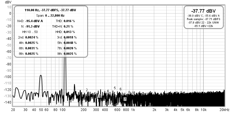
The above shows the distortion with a series 2.2μF polarised electro between the output of the test set and the 100Ω resistor. Admittedly, I'm unable to get accurate levels below about -120dB because the system noise floor won't let me. Unlike the test described above, the distortion is not attenuated by the capacitor, so what you see is the distortion contributed by the capacitor with 980mV across it. This is well beyond what anyone would use for coupling, as 17dB is dropped across the capacitor at 110Hz. Normally, a much higher value would be used, between 100-220μF. Very little voltage appears across the capacitor. As noted earlier, if there's almost no voltage across a capacitor, then it can contribute almost no distortion. Even in this test, the THD is much lower than you'd expect. It's actually hard to see just how the cap has increased the distortion, as the harmonic levels are similar to those measured without it in circuit. However, the harmonic levels may be much the same, but the fundamental (110Hz) is 17dB lower, so the relative harmonics have increased (the distortion measurement shows 0.016% excluding noise).
This is not a definitive test, simply an example of a couple of measurements I took on a randomly selected capacitor. If you need proof for yourself, you'll have to take your own measurements, using a selection of different capacitors, and at a range of AC signal levels. You may wish to add DC bias or drive the cap(s) with a higher voltage, or conduct other tests based on your requirements. If you want definitive, read the series of articles by Cyril Bateman (See Reference 3.
Ceramic caps deserve a section to themselves, because they are quite specialised and cannot be treated as 'any old cap'. Low value NP0 (negative/ positive/ zero aka C0G) types are often used as a Miller capacitor in power amplifiers, and are also common for stabilising uncompensated opamps and for HF rolloff (to prevent RF interference for example). Values used are were almost always below 1nF, with the most common range being between perhaps 10pF up to 220pF. Most are rated for 50V, but I've tested them at 500V and have never seen one break down.
NP0 (and C0G) means that these caps have close to zero temperature coefficient, and they are traditionally very stable because their main purpose in life is for tuned RF circuits. Continuous use with an AC voltage of up to 50V RMS has never caused a 50V NP0 cap to fail in my experience. This class of ceramic cap is very stable with both voltage and temperature, and they can be used anywhere within the signal path. Temperature stability is typically ±30PPM (parts per million).
Multilayer ceramics are now separated into three classes, Class I (NP0, U2J) which are stable but have relatively low capacitance for their size, and Class II, being higher capacitance but with relatively stable performance, and Class III, having great sensitivity to voltage and temperature. In general, avoid Y5V and Z5U dielectrics if at all possible.
Multilayer ceramics (aka MLCC - multilayer ceramic capacitors) are commonly referred to as 'high-k' types, because the ceramics used have a very high dielectric constant. Unfortunately, this high 'k' value is not stable, and the dielectric constant varies with applied voltage and temperature. A 100nF bypass cap with 15-30V DC across it (very common with opamp circuits) may have an actual capacitance of perhaps 80% the claimed value, so might only be ~80nF. Fortunately, this is almost always more than sufficient to ensure that opamps don't oscillate due to power supply track inductance. High-k ceramics caps also have a high temperature sensitivity, and all parameters (insulation resistance, capacitance and dissipation factor) are affected.
You could be forgiven for assuming that the voltage sensitivity could be put to good use, and you could make a tunable filter or oscillator by using a high-k cap as a 'varicap', and you could tune the device by changing the voltage across the cap(s). Unfortunately, while this will actually work, the temperature coefficient is such that the tuning frequency will vary too much as the ambient temperature changes.
You also need to consider that if any high-k ceramic capacitor has significant signal voltage across it, the capacitance will change and will be different for different signal amplitudes. This means that distortion is inevitable! It might not be very much, but it will be easily measurable and will have an effect on the sound. Whether you'll actually hear the distortion is another matter.
Some of the issues with ceramic caps include instability (capacitance varies with applied voltage and temperature) and, of considerable importance to audio, many are also microphonic (see next sub-section). Microphony is not an issue with very low values used for amp (or opamp) stabilisation, but it could be a disaster for higher values that might be used as coupling caps. Well over 40 years ago, I discovered this problem in an amp that I manufactured, where a 19mm diameter 220nF ceramic was the only economical alternative at the time. The caps had to be glued to the back of a pot to damp the microphony (they were part of the tone control circuit). The extra mass of the metal pot and the resilient contact adhesive was a success.
Microphony is due to the ceramic itself, which becomes (slightly and accidentally) piezoelectric, so the ceramic flexes with signal and generates a signal when flexed. The sum total of the problems with ceramic caps is such that they are not recommended at all for any audio signal coupling or filtering application.
| 1st Char Tempco - ppm/°C | 2nd Char Multiplier | 3rd Char Change Over Temp °C | |||
|---|---|---|---|---|---|
| Char | Temp | Char | Temp | Char | ppm /°C |
| C | 0 | 0 | -1 | G | 30 |
| B | 0.3 | 1 | 0.3 | H | 60 |
| L | 0.8 | 2 | 0.8 | J | 120 |
| A | 3 | 0.9 | K | 250 | |
| M | 4 | 1 | L | 500 | |
| P | 5 | 1.5 | M | 1,000 | |
| R | 6 | 2.2 | N | 2,500 | |
| S | 7 | 3.3 | |||
| T | 8 | 4.7 | |||
| U | 9 | 7.5 | |||
Class I caps are considered to be stable, although compared to film caps that might be debatable. The dielectric is generally calcium zirconate, with a relatively low dielectric constant and low capacitance per unit volume. These types have a temperature range from -55°C to 125°C. High dielectric constants invariably lead to higher sensitivity to temperature and voltage. Class II ceramics use barium titanate dielectrics, leading to higher capacitance (×1,000 up to ×10,000!). Of these, the Y5V and Z5U give the most capacitance, but show very high temperature sensitivity. These are in a class of their own - Class III.
| 1st Char Low Temp °C | 2nd Char High Temp °C | 3rd Char Change Over Temp °C | |||
|---|---|---|---|---|---|
| Char | Temp | Char | Temp | Char | % Change |
| Z | +10 | 2 | +45 | A | ±1.0 |
| Y | -30 | 4 | +65 | B | ±1.5 |
| X | -55 | 5 | +85 | C | ±2.2 |
| 6 | +105 | D | ±3.3 | ||
| 7 | +125 | E | ±4.7 | ||
| 8 | +150 | F | ±7.5 | ||
| 9 | +200 | P | ±10 | ||
| R | ±15 | ||||
| S | ±22 | ||||
| T | +22, -33 | ||||
| U | +22, -56 | ||||
| V | +22, -82 | ||||
The table shows the various dielectric designations for high-k ceramic caps. Not all are available, and the most common are X7R and Z5U. Of these, X7R is preferred as it has a much lower thermal and voltage coefficient than the Z5U, and also works over a wider range of temperatures. Volumetric efficiency isn't as good so they are larger, but have fewer problems. Note that there is no specification for voltage coefficient, and some high-k dielectrics (particularly with the smaller SMD parts) can have such a high voltage coefficient that a 100nF cap may be reduced to less than 10nF at little over half the rated voltage! These high-k (Class III in particular) ceramics also have a problem with ageing - they will lose capacitance as they get older, with most of the loss occurring early in the cap's life [ 7 ].
The above is adapted from a paper by Kemet (Here's What Makes MLCC Dielectrics Different) [ 15 ], and it shows the relative characteristics of the various dielectrics. It's quite apparent that Y5V and Z5U are in a class of their own. These should be avoided when possible, but you may not be aware of the dielectric material unless you read the datasheet. This is always available from reputable suppliers, but if you shop for parts on eBay or the like, be prepared for the worst.
Most of the large capacitance values you see in modern equipment (e.g. 10μF to over 100μF) are X7R, and these are considered to be fairly stable and have low ESR. They are available with up to 500V rated voltage, and can handle reasonable ripple current (up to 4A in some cases). These are smaller than an equivalent electrolytic capacitor, but are more expensive. They've become popular because of ever-increasing power density in switchmode power supplies, where their small size reduces overall volume. They are not recommended for audio coupling, and are definitely not suited to filters, as their distortion becomes easily measurable (and may be audible).
An article recently came to light that looked at capacitance loss when X7R MLCC caps are subjected to a continuous bias voltage [ 16 ]. The material I saw was originally from Vishay, and (as expected) it showed them to be superior to other makes. However, if a 50V cap is subjected to 50V for 1,000 hours, expect its capacitance to have fallen by up to 25%. When the DC is removed, there is some recovery, but it takes time (typically 1,000 hours of operation needs 1,000 hours to recover). This should disabuse people of the idea that leaving equipment powered 24/7 is somehow 'better', as this is clearly false for MLCC caps. Naturally, all other parts that are stressed continuously will have a shorter life as well.
There are special ceramic types that are marked as 'Y' class (in particular, 'Y1'). These are intended to decouple hazardous voltages to SELV for EMI reduction, and are supposed to carry safety certification. All 'Y' class ceramic capacitors must have all the approvals required for countries around the world, and they are usually covered in approval logos. Common values are 1nF or 2.2nF (the range is typically 10pF to 4.7nF), and they are rated for continuous use at 250V AC, and are tested at up to 4kV AC. These capacitors are special purpose, and are not applicable to normal audio circuits, other than in switchmode power supplies. See X And Y Class Capacitors below for some detailed info on specialised EMI capacitors.
Indeed, 'Y' caps were very uncommon until double insulated (no earth/ ground connection) switchmode power supplies became popular, and they can be found in almost every (approved) switchmode plug-pack (wall-wart) or in-line power supply available. Be very careful when buying such supplies (especially very cheap ones from China), and make sure that they carry the proper approvals. Be aware that just because there are approval marks on the supply, that doesn't mean they are legitimate! I have seen such supplies where the 'Y' cap is no such thing - it's a normal high voltage ceramic, and has zero safety certification! Although there is no direct evidence at the time of writing, don't be surprised to find that fake Y1 caps are being used - most likely normal high voltage ceramics with the required logos added later by unscrupulous resellers.
So, ceramic caps have their uses, NP0/ C0G types are perfectly alright as Miller caps on power or opamps (and do not add distortion). Multilayer X7R or Z5U dielectric caps are perfectly suited for bypassing/ decoupling opamp supply rails, and don't believe anyone who claims otherwise. They were designed for just this purpose!
However, never use any multilayer or other high value (high-k) ceramic capacitor for audio coupling, in filters (such as electronic crossovers, tone controls or infrasonic filters) or anywhere else in the signal path. These caps are designed for supply rail decoupling, and not to replace film caps.
There's quite a bit of information available on this topic, but fortunately (at least for audio applications) it isn't usually a problem. High-k ceramic caps will almost always have a piezoelectric effect, meaning that they will vibrate when subjected to an alternating current and will generate a voltage if vibrated. Of particular concern are high-value ceramic caps (10µF or more), as they are physically larger. The capacitor itself will normally be silent, but the PCB may act as a 'sounding board', amplifying the noise to the point where it can become audible [ 14 ]. As noted in the reference, there are solutions.
No purely analogue solution (using opamps or discrete components) will have a problem, especially if built using through-hole parts. I never specify high capacitance multilayer caps in any design published, with the largest normally suggested being 100nF. Since these are used in parallel with opamp supply pins, they have an electrically quiet environment to start with, and as they are through-hole the opportunity for noise is negligible.
Where this issue becomes problematical is with SMD caps, subjected to a noisy supply, and especially in small 'personal' devices where size and cost preclude the use of 'acoustically silent' capacitors. Many of these may also utilise thinner PCBs than more traditional circuits, allowing the PCB to flex more easily. In general, this isn't something you'll need to worry about with any of the ESP projects, but it is something you need to be aware of.
Electronics World did an epic series of articles written by Cyril Bateman [ 3 ], where he went to extreme measures to develop equipment to be able to measure the distortion of common capacitors. Again, this was done with an AC voltage applied across the cap, so the results are generally of far less importance for a coupling cap. The findings are useful for determining the usefulness of various caps in filter circuits (especially passive crossover networks) though, and he quickly disposes of a number of persistent myths, including (but not limited to) the following:
For anyone who wants to examine these findings in greater detail, I strongly suggest that you get hold of the original series of articles. In general, it was found that the distortion of capacitors was generally very low - well below that contributed by the majority of active circuits. There are very good and valid reasons not to use certain capacitor types in some applications, and equally good reasons to insist on their use in others.
As described above, for bypassing, so-called monolithic (multilayer, high-k, etc.) ceramics are very good, having a low impedance up to hundreds of MHz, assuring good supply bypassing at the highest frequencies. As frequency increases further, standard ceramics are usually preferred. Using them in an audio active crossover network would be a very bad idea though, because their capacitance tolerance is not good, and the value can also change with applied voltage and temperature. Some ceramics (high k types being the worst) may be microphonic due to the piezoelectric properties of the ceramic substrate. Modern multilayer caps are much smaller than early high-k types, and are less likely to suffer from microphony, it is well worth bearing this potential problem in mind. As with dielectric absorption, microphony is more likely to be a problem in high impedance circuits. In most audio applications it will rarely be an issue, but ceramics in general are not recommended for filters, or as coupling caps in audio circuits. This is because of wide tolerance and capacitance variations with frequency and temperature.
G0G or NP0 ceramics have very low temperature coefficients, and are generally useful in many areas of audio where small values are needed. In particular, they can be used as RF suppression, or as the Miller cap in power amplifiers. While it is generally thought that polystyrene or silvered mica (for example) would be better, this may be more of an expectation than a reality. This is something I have tested, and have been unable to measure any difference in distortion between a polystyrene and ceramic cap. Frequency response is essentially unchanged, as is slew rate.
Electrolytics are excellent for power supplies, and most other places where high values of capacitance are needed. They are unsuitable for filters, because they have wide tolerance, should be biased, and may change capacitance depending on applied frequency. Bipolar electros are ok where high values are needed, and no polarising voltage is available. Because of wide tolerance, they too are unsuitable for filter circuits. The distortion caused by electrolytic caps used for signal coupling (including their use in feedback networks to ensure unity DC gain) is low to immeasurably low if they are selected to have minimum AC signal voltage developed across them at all frequencies of interest.
While it is a widely held belief, it is not essential to maintain a polarising voltage across an electrolytic cap. However, the capacitor value must be high enough to ensure that no more than ~100mV peak AC voltage (70mV RMS) ever appears across the cap in normal use. Provided you follow this recommendation, polarised electrolytic caps will last for many, many years with no DC voltage across them. Distortion is measurable with very sophisticated equipment, but is generally so low that it can be ignored.
When it comes to high current applications (such as passive loudspeaker crossover networks), there will be significant voltage across the cap and current through it. It pays to use high quality capacitors that can withstand the voltage and current that the caps will be subjected to - this generally means polypropylene, polyester, or perhaps paper-in-oil (if you must). This is an area where dielectric loss may cause the caps to heat up with sustained high power, and the devices used need to be stable with time and temperature. Do not necessarily expect to be able to hear any difference between these (high quality) types in a blind test though, as you may well be disappointed.
One thing that may be very important for passive crossover networks is the material used for the 'plates' of the capacitor. Metallised film caps may not be the best choice because of the resistance of the film itself. The film is usually extremely thin, and it may not have a low enough resistance to allow the full current required. I have not experienced any problems with this, but a film and foil type is more suited to high current operation than a metallised film construction. This topic is mentioned on capacitor manufacturers' websites, and I recommend a search if you want more information about current handling capacity.
Bipolar (non-polarised) caps are (IMO) simply unsuitable for use in passive crossovers. They are very small for their capacitance so self-heating likely ... either because of power lost in ESR or dielectric losses. Wide tolerance also means that the network will probably not be right unless it is tweaked, and it will change with time anyway. Distortion is easily measurable when there is a significant voltage across the capacitor.
The standard (subjectivist) test method with capacitors (indeed, with many electronic components) seems to be to exchange a standard unit with one often costing a great deal more, then to proclaim that ... "Yea indeed, behold the huge difference", and "Lo, hear how great is the improvement". As I have noted many times, this is flawed reasoning, and any such test is utterly invalid. Nothing can be gained from this except a continuation of the 'pure subjectivist' dogma.
In a properly conducted test, the test methodology will force the listener to determine if there is a difference between two pieces of equipment (or even any two components), and do so without knowing in advance which is which, and, to do so with statistically significant accuracy. This is usually taken to be around 70% - the listener must pick 'Part A' from Part B' correctly at least 70% of the time.
According to the claims one might hear from some people regarding their favourite capacitor (or anything else), any blind test should score 100% accuracy, such is the difference heard. Sadly, it seems that in any blind (or ABX) test, the difference fades to nothing, and test results are nearly always inconclusive - it cannot be said with certainty that a difference was heard or not. I cannot understand how something can be claimed on one hand to be 'chalk and cheese', yet cannot be reliably identified as soon as the visual cues are taken away. This should alert everyone to the fact that experimenter expectancy and/or desirability are the overwhelming factors, and that the components themselves are sonically virtually identical.
The actual testing of components must be done with care. The components must be tested in a manner that reflects the way they will be used in practice, or, if this fails to yield any measurable result, the degree to which the part is pushed beyond its ratings must be explained. The report should then extrapolate (in as far as practicable) the measured results at elevated operating conditions to the expected result at normal levels. That this is rarely (if ever) done is fair warning of the likelihood of erroneous data being propagated.
I have never been able to measure the distortion of a capacitor that is used sensibly in a real circuit. This is partly because the equipment I have does not have the extraordinary resolution needed to be able to measure such low levels of distortion, and partly because the active circuitry and system noise will usually predominate. There is little point trying to measure signals that are -100dB below the 1 Watt level, or even worse, at -100dBu (i.e. referred to 775mV).
For example, let's look at distortion at -100dB referred to full power of an amplifier. Assume that the loudspeakers are 90dB/W/m and the amplifier is 100W. The peak SPL is 110dB (unweighted) at 100W, and you might be blessed with an exceptionally quiet listening room - let's say 30dB SPL. If you have distortion artifacts at -100dB, then with a peak SPL of 110dB, the distortion will be at 10dB SPL unweighted (110dB - 100dB). Your very quiet listening room is a full 20dB noisier than the loudest distortion components!
Based on my own observations, as well as those from many others (Bateman, Self, et. al.), capacitor distortion in any real circuit will generally be (much) less than 0.001% ... that's a level of -100dB. Testing and obtaining good results at these levels is highly problematical. Circuit noise, residual distortion and even a tiny bit of corrosion on a connector will increase the measured distortion dramatically. Cyril Bateman was forced to build specialised test equipment to measure the distortion, and while anyone can do the same, it is time-consuming and expensive to do so.
Returning to the use of a cap for signal coupling ... let's assume a seriously non-linear capacitor as shown in Figure 2.1. when used with significant current through the cap (A), the simulated distortion is 1.26% at V1. When used for coupling, distortion is zero - there is simply not enough current through the non-linear circuit to cause a problem. Real tests show the same behaviour - the 1µF polarised cap that so happily gave measurable distortion before shows none that I can measure. The simulator also shows zero distortion at V2 when the non-linear cap is connected as a coupling capacitor (B). It is not until the load resistor (22k) is reduced sufficiently to cause significant voltage across the cap that distortion becomes measurable. For example, when the 22k resistor is reduced to 1.5k, distortion rises to 0.0076%. At 600Ω, distortion is 0.85%. The diode shown is 'ideal', so it will conduct at very low voltages.
Although this is obviously a simulated experiment to show the general principle, reality (including test results on the same electrolytic cap that produced measurable distortion before) is very close. If a capacitor is going to cause measurable distortion, then the signal voltage across it must be significant. If this is not true and there is negligible voltage across the cap, then it is quite reasonable to expect that the contribution of the component at that frequency is also negligible. Any inherent distortion it produces must be considered in combination with the voltage across it. A capacitor (or any other component) with zero volts across it contributes zero distortion, so extrapolate from there, and not from the silly and pointless claims that "capacitors cause distortion".
When used in filter circuits, capacitors no longer have next to no voltage across them, so some distortion is inevitable. However, your test methodology had better be very robust to ensure that any distortion measured is actually from the capacitor, and not due to anything else. It's all too easy to jump to conclusions that don't hold up to scrutiny.
All capacitors have some inductance, but what is often overlooked is that the leads are the primary cause for this. To minimise the inductance, keep the leads as short as possible, and keep them as close together as possible. When two conductors are run in parallel, they form a capacitor. By maximising the (capacitive) coupling, you automatically reduce the inductance. Loudspeaker cables have been produced that have extraordinarily low inductance, despite the fact that they are quite long, and should (in theory) have high inductance as well. Not so. They have high capacitance (sufficient to give many amplifiers severe heartburn), but inductance is low. The closer the conductors are spaced and the greater the physical area, the greater the capacitance and the lower the inductance.
Now, consider a conventional wound film and foil (or metallised foil) capacitor ... even if the plates were not joined at each end to form a (relatively) solid block (see Figure 02, or do a Web search for capacitor construction), the capacitance would be at the required value, and inductance would still be negligible. The mechanism that supposedly causes internal inductance has never been demonstrated for film caps, but a great many measured results have neglected the capacitor lead length, resulting in erroneous figures. The errors can easily exceed an order of magnitude with a poorly set up experiment.
The measurement must be taken from a point as close as possible to the capacitor. If the measurement is taken even a few millimetres away from the capacitor itself, it will include the lead inductance. This is made worse by spreading the legs of the cap to allow convenient connection. The inductance of the leads can be calculated by [ 4 ] ...
LDC = 2 × L × [ ln ( 2 × L / r ) - 0.75 ] nH where LDC is the low-frequency or DC inductance in nanohenries, L is the wire length in cm, r is the wire radius in cm, and ln is the natural logarithm
The inductance is not great ... about 5-10nH per cm (centimetre) depending on wire size, but it is still significant at very high frequencies. With a 1µF cap (hardly massive), a mere 6mm of lead length (6nH assumed) creates a series resonant circuit at close to 2MHz. Increase the capacitance to 10,000µF, and it is now 20kHz. This is not capacitor resonance, it is a resonant circuit formed by the capacitor and the external inductance of the capacitor's leads. For bypassing applications, the resonant circuit so formed does not reduce the effectiveness of the bypass capacitor if it is 'too big'. In reality, power supply bypass capacitors will supply the current required by the circuit regardless of the 'self resonant' frequency, so small values of capacitance do not mean better bypassing.
Figure 3.0.3 shows a simulated power supply and switching circuit, with inductive leads to the MOSFET and its load. Given the 'self resonant' frequency of the capacitor and lead inductance (about 35kHz with a 1,000µF cap), one would expect that the pulse performance would be woeful, but it is essentially unchanged as C1 is changed from 1µF up to 10,000µF. If the value is reduced (less than 1µF), then performance does suffer. Lower capacitance does not give better bypass performance.
In Figure 3.0.3, you can see the waveform of the switching pulse with (red) and without (green) the series inductance and resistance - a comparison between a real and a perfect (ideal) capacitor. Note that there is very little difference. This, despite the fact that in theory the 'combination' capacitor has a series resonance of 35kHz, and the switching speed is many, many times that. Using a much smaller capacitor (such as 100nF) is a disaster, allowing the circuit to ring, and develop excessive back-EMF. Feel free to perform the test using real components - you will get very similar results!
The bypass capacitor equivalent circuit as shown is rather pessimistic. The 20nH inductor is actually a low Q component because of many system losses, and would normally be shown with some parallel resistance. The following plots were done with the high Q inductor as shown, hence the much sharper than normal impedance dip shown in Figure 3.0.5. In reality, this is a very broad notch because of the low Q of everything involved. For bypass applications, the low Q is a good thing and works in our favour.
An important thing that is often missed is that the resonance formula ( fo = 1 / 2 π √ L C ) only implies that higher capacitance values cause lower 'self-resonance' and worse high frequency performance. This is largely untrue - the ability of the larger capacitor to supply instantaneous current demands is not impaired, so the idea of using a small cap ("well, they have a higher self-resonant frequency don't they?") in parallel with a big cap is essentially nonsense - more capacitance equals more energy storage. The concept of 'self-resonance' in this context is flawed thinking, and leads to silly designs (100nF caps in parallel with 10,000µF electros for example) that generally achieve nothing useful, other than using more components.

In Figure 3.0.4, you can see the difference between using a 1,000µF (red) and 10µF (green) non-ideal bypass capacitor, measured at the positive supply to the switching circuit. The 1,000µF cap should show a sluggish response because its 'self resonant' frequency is so low. As power is demanded (MOSFET switched on), there is no difference at all, although recovery is a tiny bit slower. Not fully visible is the fact that the low value cap causes a damped oscillation, whereas the higher value does not. So, do low value caps 'work better' as bypass? ... No, in general they do not.
Figure 3.0.5 shows the impedance of a simulated 1,000µF capacitor with 20nH series inductance and 10mΩ series resistance. The 'self resonance' frequency is 35kHz, with a minimum impedance equal to the series resistance (ESR). Even at well above the resonant frequency, the cap still provides capacitive energy storage - it is not an inductor, despite appearances. This is commonly claimed, but is generally untrue. The impedance is increasing, but until such time as the inductive reactance becomes significant (with respect to the circuit impedance) the composite circuit is still a capacitor. Even at 1MHz, the total impedance is only 125 milliohms. Although the 125mΩ is almost all inductive reactance, it cannot be considered 'significant' (a somewhat vague term that is usually taken as around an order of magnitude compared to the load). In this case, the load is 10Ω, so 1Ω is 'significant'. This occurs at 8MHz. It is very important to understand the difference between a supply bypass application and a tuned circuit or other electronic function. Note that self resonance in electrolytic caps is very broad because both internal (large) capacitance and (small) inductance are low Q.
At least one person has declared that the above is garbage, but only after taking the material out of context and deciding that I also include RF transmitters as part of 'audio' (strangely, no, I don't). The simulations are accurate, and if the silly claims of self-resonance were true, no-one would be able to use 100,000µF filter caps (for example) because the self resonant frequency would be well within the audio range. Strangely, most amps work perfectly well at all frequencies with very large filter caps, even where the theoretical self resonant frequency of the power supply is within the audio band because of very large capacitance.
In a normal circuit (such as a series tuned circuit for example), when the applied frequency is the same as the resonant frequency of a capacitor and inductor (including leads, PCB tracks, etc.) the tuned circuit is no longer reactive - it is resistive! The resistance is equal to the sum of all component and lead resistances (including ESR). Below resonance, the circuit is capacitive - above resonance, inductive. Series resonance in a capacitor may result in rather unexpected behaviour in high frequency circuits (including digital), depending on the specific application.
It is obvious that capacitor leads should be kept as short as possible, and it might be an advantage if manufacturers stopped spreading and kinking the leads of monolithic ceramics in particular, as this introduces a (small) additional inductance because of the lead length and reduces the maximum operating frequency. (It's usually done so that soldering doesn't damage the cap.) It is quite obvious that lead (and PCB track) inductance must be considered for very high frequency circuits - or for circuits that are capable of very high frequency operation even though they are used at much lower frequencies (audio amplifiers come to mind). Where very high frequencies are involved, there will be a significant advantage if SMD (surface mount) capacitors are used, as they have zero lead length and are very short, so have extremely low inductance.
Some interesting observations are made by Ivor Catt [ 5 ], where it is maintained that the vast majority of capacitor claims are false. His information on bypass caps (in particular) goes against all 'conventional logic', yet the simulation described above validates his theory. A couple of his more notable quotes are ...
Ivor is considered eccentric to many in the electrical/electronics fields (some may say that is an excessively generous description), but his data cannot be dismissed out of hand. Particularly when a simulation shows that a capacitor, even with series inductance, can supply the instantaneous demands of a switching circuit. This is despite that fact that the switching occurs at a frequency that is well above the 'self resonant' frequency of the capacitor.
Another of Ivor's contentious claims is that a capacitor is a transmission line. Based on the tests conducted (see ESL & ESR below), there is much to commend this model, even though it has been scoffed at by many who (in my opinion) should have been thinking more clearly. A length (any length) of coaxial cable appears to be capacitive at low frequencies, and at a frequency determined by its length, shows series resonance - it becomes (almost) a short circuit for that frequency. Above the resonant frequency, the cable is inductive. The primary difference is based not on any of the counter-claims that I saw to the suggested model, but because the very construction of a coaxial cable is such that it has vastly lower capacitance than any real capacitor. Because of the low dielectric losses, the resonance is very high Q. In addition, the cable's capacitance and inductance are optimised for the circuit impedance. Capacitors are optimised for capacitance (what a surprise), so generally use a dielectric that is far thinner and has somewhat greater losses than coax. That does not change the basic model though - it simply means that the characteristic impedance of any given capacitor is dramatically lower than that of any 'normal' transmission line.
It is probable that if a capacitor were to be laid out flat rather than rolled up in the normal way, its inductance will not increase by anywhere near as much as the pundits might imagine. This, despite the fact that when it is rolled up, the entire edge of each plate is joined, so the 'length' of this transmission line is the width of the metallised film (or separate foil). This agrees quite well with the measured or calculated internal inductance of almost all capacitors, and this is easily verified by anyone with access to basic RF test equipment.
One claim that is even described as "as everyone knows" is that large caps are 'slow' and small caps are 'fast'. This is (of course) unmitigated drivel. If you want proof (possibly at the expense of the test cap), charge a 100,000μF (100mF) cap to it's maximum rated voltage, then short the terminals together with a short piece of wire. If possible, monitor the voltage across the piece of wire with a scope. The reaction is instant, violent and very fast.
The series resonance of an electrolytic (or any other capacitor) has to be considered in conjunction with the circuit impedance. In real life devices, it is actually quite a broad null, often extending over several decades of frequency. This is readily apparent from looking at manufacturers' data, or by measurement. Measurement is actually quite difficult, since a significant current must be applied to be able to see the results. This requires an amplifier with very wide bandwidth indeed, and although some esoteric audio amps may be capable of providing sufficient current to obtain a worthwhile reading, most cannot.
It is notable that series resonance frequency for large electros is usually quite low, and it's easy to imagine that this is due to the cap's ESL - allegedly massive by some accounts. Not so at all. The answer is simple - the frequency is low because the capacitance is huge. Inductance is generally low as can be seen in Figure 3.1.1, where adding just 20nH (~20-25mm of straight wire) makes a significant difference. If the internal inductance were huge as claimed, adding 20nH would make no difference at all because it would be negligible by comparison. For the following, I've assumed 10nH for each 10mm (1cm) of wire.
Something that is somewhat easier is to apply a squarewave at (or near) the approximate series resonant frequency. Although the graphs in Figure 3.1.1 are simulated, the simulation is based on actual measurements, using a 15,000µF 35V electrolytic capacitor. This component has a series resonant frequency of around 40kHz, however, this comes with caveats. It is a very broad resonance (as expected), and with 10V RMS applied via a 10Ω resistor, I was able to obtain a readable trace on the oscilloscope.
The following graphs show two traces ... the first (red) is the waveform across the cap with 20mm of lead between the cap and the measurement point. The second (green) is with the frequency analyser probes placed as close to the capacitor as possible. A mere 20mm of lead equates to approximately 20nH of inductance, but as seen in Figure 3.1.2, that is enough to double the amplitude of the spike at the leading edge of the waveform. It is also enough to lower the 'self resonance' quite dramatically - the low frequencies are unchanged, but the high frequency (where the impedance starts to rise) is moved down by nearly 400kHz. The minimum amplitude difference is because of the lead resistance (simulated as 10 milliohms).

These simulations agree quite closely with the measured results, so even though there will be some variance, it will be less than that obtained from different samples of real-world components. As with the pulse response, there was exactly zero measurable difference when a 220nF film cap was added in parallel - either with the extended leads or without. The simulation agrees for the most part (but only if a 'real world' capacitor with losses is used), and I have not included these data.
In a real circuit, there is a possibility that a small film capacitor in parallel with a large electrolytic may cause ringing (damped oscillation) at a frequency determined by the series inductance of the electro (and any leads connecting to it) and the capacitance of the additional film cap. This is more likely to degrade performance than improve matters. It is possible to simulate this easily, but it is not so easy to measure because the frequency will be very high, and the impedance still very low. Because this possibility is rather remote, if it makes you feel better, by all means add a parallel film cap with minimal lead lengths between the film cap and the electro. Don't expect to hear a difference in a blind test though, because you almost certainly will not.

The pulse response is interesting. This is as close as I could get to the actual measured waveform, and contrary to common belief, adding a parallel capacitor (in this case 220nF) did not change the measured pulse waveform one iota. The impedance of the film cap is simply much higher than that of the electro, so it cannot have any significant effect on the end result. There is an effect, but it is immeasurably small. The impedance (capacitive reactance) of an ideal 15,000µF cap at 1MHz is 10mΩ, but we must add the ESR to that result. According to the simulation, the total impedance is 134mΩ at 1MHz - inductive reactance is responsible for most of that. By comparison, an ideal 220nF capacitor will have a reactance of 723mΩ at the same frequency - more than 5 times that of the electro.
Earlier, I made the comment that for resonance to actually work as expected, the circuit impedance must be 'significant' compared to the resonant impedance. It is time to examine exactly what is significant, and what is not. The resonant frequency of a capacitor and inductor is given by the equation ...
fo = 1 / ( 2π × √( L×C ))
This is a general formula, and while it holds true in all cases, the Q (quality factor) of the resonance is dependent on the circuit impedance and component losses. In the case of electrolytic capacitors (especially large ones, where the resonant frequency is comparatively low), the capacitance is massively dominant compared to inductance. For this reason, electros will rarely (if ever) appear as a resonant circuit in any power supply or coupling capacitor application.
The coupling cap is a good one to examine, because this is an area where it is often thought that a parallel capacitor will assist with high frequencies. If we assume a 4,700µF capacitor, having 100mΩ ESR and an inductance of 100nH (this is much muchworse than any real capacitor), its 'resonance' is at 7,341Hz. The test circuit is shown in Figure 3.0.1. As a coupling capacitor, it might appear to have inductance above the self resonant frequency, or so it would seem. Not so, as Figure 3.1.2 shows. In fact, the frequency response into an 8Ω load remains substantially flat up to 4.5MHz (0.5dB down), and is -3dB at 12.7MHz, despite the gross exaggeration of ESL.
In Figure 3.1.3, you see that the 100nH of inductance in the capacitor is totally insignificant compared to the circuit impedance (8Ω) and the capacitance. The speaker and lead will have a great deal more inductance than the capacitor, so the high frequency limit will be lower than calculated. 'Limitations' caused by ESL don't happen ... well, actually they do happen, but the effect is so infinitesimally small that it can only be measured by simulation. In the example given, the difference between the voltage across the load resistor at 100kHz is reduced by less than 250µdB (micro decibel), compared to the 7.3kHz 'self resonance' frequency. Any effect seen is well outside the audio frequency range, and is completely swamped if a series inductor is included in the circuit to isolate the amplifier from high capacitance (low inductance) speaker leads.
However, should you want to test the capacitor itself (highly recommended if you can), the connection of the measurement instrument (most commonly a scope) is critical. It must be connected to the cap with as close to zero lead-length as you can manage. You can then experiment with the lead length to see for yourself how even a short length of component lead changes everything. You will need a signal generator that can get to at least 10MHz for meaningful results (I used up to 25MHz for bench tests). For a given ESL, a larger cap produces a lower frequency.
For example
f = 1 / ( 2π × √( 10nH × 10µF )) = 503kHz
f = 1 / ( 2π × √( 10nH × 100µF )) = 159kHz
f = 1 / ( 2π × √( 10nH × 1mF )) = 50kHz
Despite claims to the contrary you may find, the capacitor does not stop passing current above resonance, because the inductive reactance is so low. As noted further below, 10nH of inductance only has 1.57Ω of reactance at 25MHz. The capacitive reactance is 6.37µΩ at that frequency, and ESR will be between 0.5 and 1Ω for a 1mF (1,000µF), 10V electrolytic cap (I measured 600mΩ).

For self resonance to be noticeable, the circuit impedance needs to be in the same general range as the capacitor's inductive impedance at resonance. As can be seen from the graph, the inductive reactance only reaches 8Ω at 12.7MHz (the upper -3dB frequency). Will a 100nF polypropylene cap (or any other type) in parallel be of any use whatsoever? From the above, we can safely say "No". Its reactance will be equal to the 8Ω load at 198kHz, but at that frequency, the electro has a total impedance of about 200mΩ, making the influence of the small parallel cap insignificant.
A further test was done, using a 220µF 25V electrolytic capacitor, connected directly to the output of a 50Ω digital function generator, with an output level of 6V RMS (open circuit). Oscilloscope leads were right at the base of the capacitor, so that (almost) no series inductance was present to ruin the test. At around 1MHz, the measured voltage across the capacitor was a little under 50mV peak (35mV RMS). I measured the frequency where the output had risen by (roughly) 3dB, and it was at 8MHz (that's not a misprint). When I moved the oscilloscope probe 25mm along the lead, that frequency fell to only 3MHz. The tiny amount of inductance of a 25mm length of straight wire was enough to reduce the upper +3dB frequency by 5MHz - that is significant in anyone's language.For anyone who has the ability to generate a waveform from 1-10MHz with an output impedance of around 50Ω, this is a test that will demonstrate once and for all that capacitor 'self resonance' is rarely a problem. If your circuit has issues at high frequencies, you'll probably need to look elsewhere. I must admit that I did not expect that result, and the capacitor's overall impedance was such that attenuation was in excess of 45dB, meaning that the capacitor has an ESR of about 0.3Ω, even at 1MHz. In this case, something in the vicinity of 20nH of inductance was added by the lead, and a simulation bears out the measurement. Note too that the calculated ESR is in agreement with the 'typical' values shown in Table 4.1 - 0.3Ω is about right for a 220uF capacitor.
As a test and to prove (at least to myself) that there's no point adding a film capacitor in parallel with an electro, I set up a small experiment. Using a 6,800µF 50V electro with a 100Ω load, I applied a squarewave to the capacitor and measured the voltage across the load resistor. At 1kHz, there was no discernable difference, other than a small difference in the bandwidth of the oscilloscope between Channel-A and Channel-B. This became more pronounced at 5MHz (yes, 5MHz!), but the capacitor's response was perfect. One would expect such a large capacitor to have a fairly low self-resonance, certainly well below the 50MHz that my oscilloscope can resolve.Adding a 100nF film cap in parallel with the electro achieved exactly ... nothing. Not even the smallest difference was seen. Swapping scope channels (because Channel-B is a wee bit worse than Channel-A) showed the same. No change whatsoever - film cap on/ film cap off - no difference (this was done in 'real time'). This is what I expected, but it was rather satisfying to actually (not) see it in action. Since the voltage on either side of the 6,800µF capacitor was identical at all test frequencies (from 1kHz up to 5MHz), it's obvious that the film cap can't make it more identical. This is all the proof I need to be able to say that the simulations and calculations shown above are valid, and that the addition of a film cap is simply a wasted component.
However, it's a cheap wasted component, and if adding it makes you feel better then use it by all means. Do not claim to others that you can hear the difference unless the comparison has been made in a properly conducted double-blind test.
Update: Feb 2023
Recently I performed a few additional tests along the same lines as those described above. I tested un-bypassed 1,000µF, 10V electros in the Project 236 AC millivoltmeter, and one of the modules was tested out to 25MHz. The module with the 220µF caps used LM4562 opamps and was verified as dead flat to 4MHz - the upper limit is set by the opamp, not the capacitors. I subsequently ran tests on 1mF caps (1,000µF), extending the test to 25MHz. The scope was connected as close to the cap's body as I could manage, with no more than 1mm of lead between the cap and the probe + ground lead. The results were pretty much exactly as I expected, with ESR being dominant from 1kHz up, and an (estimated) 10nH of ESL causing the impedance to rise beyond ~6MHz. At 25MHz, moving the scope probe just 20mm down the capacitor's lead (adding another ~20nH inductance) increased the residual output very noticeably. 20mm of component lead almost tripled the voltage across the capacitor. Remember - the cap's internal inductance is 10 nano-Henrys, an almost inconceivably low value. Just 10mm of 0.7mm diameter wire raises that to 20nH.
I suspect that most readers won't have a low impedance generator (50Ω) that can extend to 25MHz or more, so you'll have to take my word for it. These results are perfectly in keeping with all other tests I've performed, but were taken to the maximum I could achieve. Electrolytic caps perform flawlessly - even at frequencies that are quite ridiculous for audio. At 25MHz, a film cap does make a small difference, but it's really hard to keep all lead lengths short enough to prevent the leads from adding so much inductance that the results become hard to quantify. It's not easy to consider 10nH of inductance as a problem, as it's such a low value. The reactance of the extra 20nH is only 3.14Ω at 25MHz!
The ESR of the 1mF cap I tested was 600mΩ, the reactance of the intrinsic 10nH ESL is 1.57Ω. Theory and practice are perfectly aligned, and a simulation of the test circuit gives almost identical results (but easier to measure because there's no noise to worry about). If you do have the ability to run a similar test, I suggest that you do so. There's nothing quite so satisfying than running an experiment like this and seeing just how sensitive it is to lead placement.
Many tests that have been conducted over the years have come up with fantastical results that 'prove' otherwise, and almost without exception the reason is excessive capacitor lead lengths. If just 10mm of wire makes so much difference, it's not hard to imagine extraordinarily poor results if there's somewhere between 100mm to 1 metre of test leads in the way. This has been missed many times, by many experimenters.
ESL - Equivalent Series Inductance
Claims have been made that most capacitors must be inductive, because they are made from a wound sandwich of film and foil, or metallised film. Because it is usually wound (in a flat coil), logically, this leads to inductance. The problem with that theory is that it assumes that the termination is made to the foil at the end only, but a quick check of manufacturer data will show that this is generally not the case. The vast majority of capacitors are made so that the foil or metallisation projects from each side (one 'plate' on one side, the other 'plate' on the other side). Each end is then connected so that all sections of the plate are joined together. This is shown in Figure 01. There is no longer a 'length' associated with the plate, and only its width becomes significant for inductance. When distortion is measured in a film capacitor, it is almost always the method used to connect to the foil that causes the problem, rather than the dielectric or foil material.
Aluminium is the most common metal for both foil and metallisation, and aluminium is notoriously difficult to attach to anything with good and reliable conductivity. That cap makers have made them as good (and as reliable) as they are is testament to the effort that goes into capacitor manufacture.
The ESL (equivalent series inductance) of any given capacitor is related more to its physical size than anything else. A larger capacitor will almost always have a greater inductance than a smaller version of the same capacity. Usually, the lead length is of far greater importance for high frequency operation.
To check the general principle, I decided to test a roll of telephone jumper wire as a capacitor. This is a fairly large roll of twisted pair (Cat-3), with the diameter of the roll being about 130mm, and 51mm high. The wire is twisted (as you would expect for twisted pair), and the roll contains about 80 metres of wire. Insulation is 0.25mm PVC, and wire diameter is 0.5mm. All in all, this should be an appalling capacitor.
Being a coil of wire, one would expect a high inductance and therefore low self resonance. The measured values were ...
Capacitance 9.67nF Dissipation Factor 0.059 Self Resonance 303kHz Inductance 28.5uH
The capacitance was measured at 9.67nF with two different meters, and DF (dissipation factor) was 0.059 ... not especially wonderful, but far better than I expected. Remember, this is a coil of twin wire, with the connection made at one end only. Inductance is calculated based on the self-resonant frequency - it is obviously much greater than a normal capacitor, but that is expected due to the physical size of the 'capacitor'. Needless to say, the fact that the connection was made at only one end doesn't help matters, but remember that this is a physically large coil of wire - one would expect that self resonance (and inductance) would be far worse than was the case.
Joining the (start and finish) ends together gave the following ...
Capacitance 9.73nF Dissipation Factor 0.059 Self Resonance 1.0MHz Inductance 2.6uH
This is a significant improvement to the inductance (roughly an order of magnitude), and also gives a small increase in capacitance. As you can now well imagine, by joining the entire edge of each capacitor plate, inductance is reduced to almost nothing, and only the physical size of the cap will influence the inductance. This can't be applied to my 'coil capacitor', because I only have access to each end, rather than the edges of the 'plates'. I think it is safe to assume that the wire coil performs far better than might have been expected, especially with the ends joined together. It also has far thicker insulation and smaller plate area than any real capacitor, both of which increase inductance and reduce capacitance.
In case anyone was wondering, the inductance of the coil that was used as a capacitor for the test just described is 15.6mH, with a series resistance of 6.4Ω. This was measured with the two wires connected in parallel. Self resonance is at 27MHz. Not useful in the context of this article, but worth including.
ESR - Equivalent Series Resistance
While inductance is not affected by the dielectric material, ESR is - it is dependent on the dissipation factor (DF) of the insulation material, as well as the resistance of the leads, plate material/ metallisation layers and plate terminations. Because DF varies with frequency and/or temperature in most common dielectrics, so too does ESR. However, ESR is rarely a problem in most audio circuits. It may be important in passive crossovers used in high powered systems, or for other applications where capacitor current is high. ESR (like all resistance) creates heat when current is passed, so for high current circuits the ESR is often a limiting factor. High ESR is a major cause of failure with SMPS (switchmode power supplies), because it reduces the damping of high-energy pulses that are characteristic of these circuits. Should transient voltages exceed the breakdown rating of switching MOSFETs, failure is inevitable.
ESR is very difficult to measure with low value capacitors, because the capacitive reactance is usually a great deal higher than the ESR itself. In general, it is safe to ignore ESR in most electrolytic and film caps used in signal level applications (such as electronic crossovers, coupling capacitors and opamp bypass applications). ESR becomes very important in high current power supplies, switching regulators/supplies and Class-D amplifiers, many digital circuits and any other application that demands high instantaneous currents that are supplied by the capacitor.
| µF / V | 10 V | 16 V | 25 V | 35 V | 63 V | 160 V | 250 V |
| 1.0 | 5.0 | 4.0 | 6.0 | 10 | 20 | ||
| 2.2 | 2.5 | 3.0 | 4.0 | 9.0 | 14 | ||
| 4.7 | 2.5 | 2.0 | 2.0 | 6.0 | 5.0 | ||
| 10 | 1.6 | 1.5 | 1.7 | 2.0 | 3.0 | 6.0 | |
| 22 | 5.0 | 3.0 | 2.0 | 1.0 | 0.8 | 1.6 | 3.0 |
| 47 | 3.0 | 2.0 | 1.0 | 1.0 | 0.6 | 1.0 | 2.0 |
| 100 | 0.9 | 0.7 | 0.5 | 0.5 | 0.3 | 0.5 | 1.0 |
| 220 | 0.3 | 0.4 | 0.4 | 0.2 | 0.15 | 0.25 | 0.5 |
| 470 | 0.25 | 0.2 | 0.12 | 0.1 | 0.1 | 0.2 | 0.3 |
| 1k0 | 0.1 | 0.1 | 0.1 | 0.04 | 0.04 | 0.15 | |
| 4k7 | 0.06 | 0.05 | 0.05 | 0.05 | 0.05 | ||
| 10k | 0.04 | 0.03 | 0.03 | 0.03 |
The table above shows the worst case ESR for new (standard, not low ESR) electrolytics for a range of capacitor values and voltages. If any cap with the value/ voltage shown has a measured ESR significantly exceeding that in the table, it is on the way out and should be replaced. The table was compiled using the details printed on my ESR meters, and is representative - some new caps will be much better than shown, some may not be quite as good, and ultimately you need to use your own judgement as to whether the measured ESR will cause a problem or not.
Some people have wondered why ESR is usually tested at 100kHz. The reason is simple - at that frequency, the capacitive reactance of a 1µF cap is only 1.6Ω, and any 'resistance' measured is therefore predominantly the ESR of the capacitor. This is why it's rather pointless to try to measure the ESR of any capacitor below 1µF - it can be done, but the measurement frequency must be much higher than 100kHz. Larger values have much less reactance, and the capacitive reactance is negligible.
Another way to measure ESR is to apply a very short pulse with a known current, and measure the voltage across the cap. This can only work with larger capacitors (typically greater than 10μF or so), using a 1μs pulse. The pulse amplitude, duration and current must be insufficient to cause the cap to charge by any appreciable amount. The measurement parameter have to be tightly controlled, because the ESR value is only valid for perhaps 100ns after the pulse is applied, and the measurement must be terminated before the pulse turns off. ESL will mess up the measurement, but greater errors are probable due to the inductance of the test leads.
I suggest that you invest in a dedicated ESR meter. Good ones aren't especially cheap, but if you're doing service work a decent ESR meter will pay for itself in no time.
Much of the information shown above is food for thought. I have had several e-mails from readers (some within a day of the article first being published), and further comments should be made to clarify a couple of important points. Much ado was made above about coupling caps, and these are a favourite of the upgrade brigade. It is not uncommon to see circuit boards where the constructor (or 'upgrader') has used caps for which the PCB was never designed. As an example, look at Figure 5.1. This is not at all uncommon, but what is not understood is the potential for possibly major problems to be introduced.

At first glance the diagram looks alright. Everything is connected where it should be, so where's the problem? Notice that the input signal is connected to the PCB via a shielded lead. The PCB may have a ground plane, but even if not, the connection between the shielded input lead is nice and short, and connects to C1 on the board. The space allowed is sufficient for a cap as originally designed.
Now, someone comes along with a massive (physically) cap that was sold as polypropylene (but could easily be polyester). It won't fit on the board, so is installed as shown. Look at the length of unshielded lead between the input terminal and the rest of the circuit on the PCB. Remember that the entire capacitor is part of the unshielded circuit, not just its leads. Even if the cap is marked so you know which is the outer foil, that doesn't help either, as any noise picked up will be coupled through regardless (this is what the cap is for!). This arrangement has the potential to pick up considerable noise, and if part of a power amplifier it may even provide sufficient coupling from the output to cause oscillation. It goes without saying that noise or oscillation will not improve the sound, even though the owner may think that it has done so.
The likelihood of noise or oscillation depends on many factors of course, and these may not be an issue (or not at a level that is audible). The mechanical reliability is also highly suspect, especially if the oversized cap has not been fastened such that it cannot move relative to the PCB. Had the on-board cap been installed in the position shown, its size is much less, and the board would have been tested with it in position - any problems would be immediately obvious.
It doesn't help anyone when (supposedly) reputable outlets make comments along the lines of "capacitors are one of the most destructive electronic components to sound quality" (and yes, that is a direct quote. No qualification was provided, just that blanket statement which was presented as a 'fact'. Well, it's not a 'fact' - it might apply to some degree in some specific circumstances, but since these were not disclosed it's simply nonsense sales-speak. Yes, as discussed earlier in this article, there are some instances where capacitors can 'harm' sound quality. However, in most cases this means using a type that's inappropriate for the intended usage, or operating the cap outside of its design capabilities.
Another point made is that series resonance can be used to your advantage. In the presence of a strong RF signal, normal bypassing may be insufficient to prevent the RF signal from getting through an audio system. If you know the frequency, then it is not difficult to tailor a ceramic cap and appropriate lead length to create almost a dead short for the interfering signal.
For example, if there is an AM CB transmitter (these operate in the 27MHz band) nearby that insists upon interfering with your audio system, you need to know exactly where it is getting into the audio path. Once this has been determined (not easy, but certainly possible), you can deduce the necessary capacitance and inductance using the standard formula ...
fo = 1 / ( 2π × √L×C )
If we assume (say) a 1.2nF capacitor, then it works out that a series inductance of 28nH is needed. With between 4-7nH/cm depending on lead configuration and diameter, the cap needs to have leads about 60mm long, and with two leads that means 30mm each. The leads need to be as widely separated as possible, and some adjustment of the frequency is possible by pulling the leads wider apart or pushing them closer together. In its basic configuration, the combination of cap and leads has an impedance of less than 1Ω between 25MHz and 30MHz, and is resonant (effectively a short circuit) at about 27.5MHz.
Maximum effectiveness is achieved when the circuit is tuned as accurately as possible, but this normally requires specialised RF test equipment. In general, a calculation will get you close enough for the circuit to be effective, and a bit of tweaking should enable you to get almost total rejection of an unwanted signal. Will this arrangement work? Probably, but the difficulty of maintaining the exact lead spacing needed means that it can't be recommended other than as an experiment.
RF is by its very nature sneaky, and deliberately using capacitor+lead resonance to solve a problem is just one of many techniques that need to be tried to solve an RF interference problem. No one method will work in all cases, and serious problems may need a combination of different suppression tricks. This applies both for preventing RF getting into a circuit, or preventing it from getting out (and therefore causing interference elsewhere). Unintended tuned circuits caused by stray capacitance and PCB tracks can cause an otherwise well behaved digital circuit to 'transmit' one or more harmonics of the operating frequency, meaning it may fail mandatory RF interference testing.
Another piece of 'food for thought' is the idea that capacitors can be 'slow' (by inference). There is one manufacturer (which shall not be named) that offers something they call a 'fast' capacitor. Although many outlandish claims are made for them, they will perform no better than any other film cap in crossovers and the like, but they will cost you a great deal more. In short, this is unmitigated horse feathers - the so-called 'fast' caps will not improve the efficiency of your loudspeaker drivers, and in a properly conducted double-blind test they will be indistinguishable from any other competent polypropylene capacitor.
There is absolutely no reason that any capacitor used in a loudspeaker crossover network (active or passive) needs to be 'fast' (with or without the quotes). It's most unfortunate that makers resort to such claims, because all they do is confuse the hobbyist (and sometimes the professional as well). As readers will know, I really dislike any company that uses BS to promote its products, and when I detect such BS, I will deliberately use or recommend components from a different maker that makes no pretense at 'better' sound at usually much higher than normal prices.
One point that needs to be made is regarding non-polarised (aka bipolar) electrolytic capacitors in loudspeaker crossover networks. Many speaker makers use them (even in often very expensive loudspeakers), but IMO these generally fall into the 'inappropriate usage' category. They are supposedly designed for just this purpose, but the current demands of a loudspeaker are often well beyond anything that can be tolerated for any length of time. This means that as the speaker system ages, the bipolar caps will lose capacitance and increase their ESR. This ruins the crossover network's frequency response, and changes the overall balance between bass and treble. Film and foil caps are considerably larger and more expensive, but are the only choice if you are building a speaker system. In real terms, the extra cost is not that great. However, a fully active system (with electronic crossover) avoids large and expensive caps altogether.
There are many places where capacitors require specific ratings, either to ensure longevity under adverse operating conditions, or for safety. X-Class capacitors are specified for use across the AC line (active/ live to neutral). Failure is usually open circuit, because if the insulation is punctured these caps 'self-heal', because the metallisation layer melts around the puncture and this removes the short. If this happens often enough, the capacitor's value will fall. In the unlikely event that an X-Class capacitor should fail short circuit, it is directly across the mains and it will blow the fuse. Note that you will see the terms 'X-Class' and 'Class X' (likewise for Y-Class), and they are interchangeable.
Y-Class capacitors are safety critical, as they are generally used between the AC terminals and user-accessible parts of the equipment. Failure is likely to cause electric shock, so only fully certified parts from reliable suppliers should ever be used when building or repairing equipment that relies on Y-Class caps. The most common reason for using them is with equipment that is not earthed via a 3-wire mains cable, but where additional protection against radiated EMI (electromagnetic interference) and RFI (radio frequency interference) is required. Switchmode power supplies almost always require one or more Y-Class caps, even if an earth/ ground connection is normally provided.
| Safety Rating | Voltage Rating | Insulation Class | Test Voltage |
| X1 | 275 VAC | n/a | 4,000 V |
| X2 | 275 VAC | n/a | 2,500 V |
| X3 | 250 VAC | n/a | None |
| Y1 | 250, 400, 500 VAC | Double | 8kV |
| Y2 | 250, 300 VAC | Basic | 5kV |
X-Class capacitors are defined as being suitable for use in situations where failure of the capacitor would not lead to danger of electric shock. Y-Class capacitors are defined as suitable for use in situations where failure of the capacitor could lead to danger of electric shock. All countries have standards that define the test limits and in the case of Y-Class caps, they will almost always have various safety certifications printed on the cap itself. Tests include insulation resistance, pulse testing, endurance and flammability.
Y-Class caps may be ceramic (the most common by far) or metallised paper/ film. Ceramic caps may fail short circuit (a serious safety hazard), but Y-Class types are certified to very high standards, and a short is highly unlikely in practice. They are generally available only in low values, with the minimum around 470pF up to a maximum value of 10nF. This much capacitance is rarely used though - most will be no more than 2.2nF, which will pass a maximum current of 159µA at 230V and 50Hz (100µA at 120V and 60Hz).
This current is enough to feel (depending on how sensitive you are), but is well below the value that will cause electric shock. However, be warned that the peak current into the input of an audio or digital circuit is sufficient to cause irreparable damage in some cases. Y-Class caps can also used for antenna coupling, where it's important to ensure that the antenna must never become live.
Safety standard compliance markings include UL, CSA, VDE, SEMKO, FIMKO, NEMKO, DEMKO, SEV, CQC and CE (logos shown in order below [ 8 ])
It's not at all unusual to see all of the above logos printed onto the capacitor, along with class, capacitance and voltage rating. Some of the standards that are applied to X and Y-Class capacitors include [ 9 ] ...
UL 1414 - USA
UL 1283 - USA
CSA C22.2 No.1 - Canada
CSA C22.2 No.8 - Canada
EN 132400 - Europe
IEC 60384-14 - International
GB/T14472 - China
Depending on where you live, there may be additional standards (as shown above) that apply. It's impractical to list every standard that applies. In general, if a component has been certified to European or International standards, it will be accepted as compliant elsewhere. This is quite obviously most important for Y-Class, but non-compliant (counterfeit or untested) capacitors across the AC line pose a fire risk.
Most Y-Class caps are ceramic, but they are also available with polypropylene (metallised film) or paper dielectric. The latter are often claimed to be safer, but I have been unable to find any credible information that describes a genuine Y-Class cap failing short circuit. X-Class caps generally use either MKT (polyester) or MKP (polypropylene) 'box' format, with close tolerances on size and lead pitch designed for automatic insertion equipment. X1 caps will almost always be polypropylene, as they are rated for high pulse current and polypropylene has a lower dielectric loss than polyester.
Note that Y-Class caps can always be used in place of X-Class, but not the other way around ! X-Class caps are safety rated for connection between active (live) and neutral, but must never be connected between active/ neutral and safety earth/ ground. Apart from the capacitor class, X-Class caps are typically available with capacitance values that are far greater than is permitted for Y-Class operation.
It should go without saying that X and Y Class capacitors are not tested for 'sound'. Their role is to minimise EMI and RFI, and discussing their sonic properties would be utterly pointless. However, it is likely that if they are omitted, sound quality could be adversely affected, because high levels of high frequency noise may interfere with digital circuits or even become audible as an interfering signal. This is most likely with AM radio, but it may also affect other equipment as well.
 | Note: Never use DC capacitors from mains to chassis or across the mains. They may survive with 120V mains, but they will fail when used at 230V AC. The infamous 'death cap' used in many old guitar amps from the US is a perfect example of what you must not do. With AC, a corona discharge will occur in any miniscule air-pocket, and that will eventually cause the capacitor to fail. The failure mode is often short-circuit, so if the chassis is not earthed (grounded) it may become live and kill someone. See Mains Safety, section 8 for the details of this particularly dangerous practice. The only capacitor permitted between either or both mains leads and an un-earthed chassis is Class-Y1. |
Capacitor can fail in a variety of ways, not all of which are 'exciting', and there are some particular failures that are 'unexpected'. In rare cases, a manufacturing defect can cause premature failure, but the most common failures are the result of using the wrong type of capacitor in a stressful circuit condition. This is particularly true of switchmode power supplies, but even there most film caps manage to outlast everything else.
I have pointed out a major shortcoming of tantalum caps, but this isn't especially prevalent (but I still won't recommend tantalum in any project). Failure of signal level caps is not common in audio equipment, especially where the caps are only used as supply bypass or for signal-level coupling. Power supply filter caps can (and do) fail occasionally, and in many cases it's simply due to old age. A proper discussion of failures and what causes them is probably worthy of an article in itself, but there is a lot of info available already - in particular from capacitor manufacturers.
Meanwhile, the chart below [ 10 ] shows the statistical failure rate for polyester capacitors. As the operating voltage reaches the maximum rated voltage (voltage ratio of 1 on the chart), it's obvious that failures become more likely. It's also apparent that the likelihood of failure increases with temperature. Any capacitor will have a limited life when operated at maximum permissible voltage and temperature. In general, if you halve the voltage ratio (e.g. use a 100V cap with no more than 50V), it's failure rate (or expected lifetime) is improved by a factor of 10.
Failure itself needs to be defined, as it's not necessarily a total failure as such. Rather, the cap may simply drift out of tolerance or become noisy (often due to excessive leakage). In the worst case, it may become short circuit or open circuit, depending on the level of abuse it has to put up with. Vibration can break leads if the cap isn't firmly attached to the PCB, or the vibration may cause the bond between the end connection and metallised foil to separate (permanently or intermittently). Some cleaning solutions can cause accelerated degradation.
If operated in 'normal' equipment where voltages and temperatures are within sensible limits, failure rates are generally exceptionally low. 'Vintage' capacitors may show excessive leakage or reduced capacitance, and high leakage (in particular) is common with waxed paper and other materials that were used before the advent of modern dielectrics and packaging techniques. As a capacitor ages, the dielectric material may show signs of microscopic cracking, which is made worse by elevated temperatures and/ or temperature cycling.
Many plastic dielectrics with vapour metallisation (metallised film) are 'self healing' if subjected to a severe transient over voltage. When an arc forms, the plastic melts, and the metallised film is vaporised by the arc. Once normal voltage is restored, the cap still functions, but with a little less capacitance than it had before because it's lost some of its area. Should this happen repeatedly, the cap will lose capacitance until such time as it's no longer able to do its job.
Electrolytic capacitors generally have a comparatively short rated life, but it's not at all uncommon for 40 year old electros in valve equipment to be working just fine. The average life for most electros is generally stated to be between 2,000 and 5,000 hours, but this is when it's used at maximum rated voltage and temperature. The expected life is usually much greater, although high ripple (or peak surge) current can cause premature failure. The life of an electro is approximately doubled for each 10°C below rated temperature (but maintained above 0°C), and the same principle applies for voltage. It's harder to pin down the actual scale, but something similar to the trend shown in Figure 7.1 is probably close.
It's notable that the ESR of an electro starts to rise well before the capacitance can be considered out of tolerance. An ESR meter is essential to test electrolytic caps, as the capacitance value can still appear perfectly alright for a cap that's either malfunctioning in circuit or causing circuit malfunction. While it's common to look for electros that are bulging (internal over-pressure), it's not at all unusual for an electro to look and measure (value) as being fine. If measuring the ESR shows an increase from the expected figure, the cap is due for replacement, even if all other signs are 'good'.
This is (by necessity) a fairly brief introduction to cap failure modes. Electrolytic caps are far less reliable than film or ceramic types, and doubly so if they are operated at high temperature, high voltage, or with high ripple current. Plastic film capacitors will usually outlast the equipment they're installed in, and failures of film caps in small signal (e.g. audio coupling) are almost unheard of.
X-Class capacitors (for mains usage) have their own peculiar failure mode. When there's a short mains overvoltage, the cap's insulation can fail. This exposes the metallisation layer, and a tiny arc will cause it to vaporise. These caps are 'self-healing', in that the fault is cleared when the metallisation layer has opened a wide enough gap to quench the small internal arc. Each time the capacitor is subjected to a voltage spike that punctures the dielectric, a small reduction of capacitance is the result. After many years in service, an X-Class cap may have lost 50% or more of its rated capacitance, something that often isn't picked up by service personnel. As the capacitor degrades, the EMI performance of the product becomes a little bit worse, and it may eventually cause interference to nearby radio equipment. In some cases, the failure may lead to product failure, for example if the cap is used to make a small, low current 'off-line' power supply (quite common in mains operated appliances that have minimal electronics). In this role, they reduce the voltage but consume no power (described in detail in the article Small, Low Current Power Supplies).
Y-Class capacitors are supposed to fail open-circuit, because even a momentary short could lead to electric shock or death. Fake Y-Class caps exist, usually in very cheap goods from China.
While most passive crossovers capacitors are perfectly alright, many are unsuitable (non-polarised electrolytic) and other 'specialty' types are seriously overpriced. In general, polypropylene dielectric is recommended because it's readily available in the sizes typically needed for a crossover network. There is absolutely no need to use exorbitantly expensive 'name brand' types, and doubly so if they make silly claims (such as saying they are 'fast'). All caps are fast (within the audio band at least), and paying much more than necessary doesn't change anything other than your bank balance. It's worth examining the difference between an ideal capacitor and one that would be considered dreadful.
If we were to assume a particularly 'bad' capacitor with far higher ESL and ESR than any cap you can buy, it's worth seeing the difference between that and an 'ideal' capacitor. We can also see if the most common silly idea (adding a smaller cap in parallel) actually achieves anything useful. For the sake of the exercise, we'll use a 5.6µF cap in series with an 8Ω tweeter, but it has massive dielectric losses (as per Figure 1.3), 2µH of ESL, plus 100mΩ of ESR. This would be a truly woeful capacitor, and I have no idea where (or even if) you'd be able to get one. ESL in particular is extremely high (but achievable if the wiring is way too long). The nominal -3dB frequency is 3.55kHz with an 8Ω load (the tweeter).
If the response of this cap is compared to an 'ideal' (i.e. perfect in every way) 5.6µF cap, the signal across the load is less than 0.11dB down at 50kHz (increasing with higher frequencies), but at the 'crossover' frequency of 3.55kHz, the difference is only 29mdB (0.029dB). If the (very poor) 5.6µF cap is now reduced to 5.5µF and an ideal 100nF cap is used in parallel (this is a very common approach), the woeful capacitor's response is 'improved' by (and wait for it ...) 1.1mdB (0.0011dB !) at 20kHz. Above 50kHz there is an improvement, but it's pointless. The response above 50kHz is due almost entirely to the extremely high ESL. The response graph is shown above (it's hard to see the difference), and I would hope that anyone who thinks this can't be right would test it for themselves.
Consider that said 'woeful' cap is vastly worse than anything you can buy, so if adding an 'ideal' 100nF cap makes so little difference to that, it follows that it will make far less difference to a half-way decent capacitor that's intended for use in crossover networks. Note that I specifically exclude bipolar electrolytic caps that are supposedly designed for crossovers. I don't use them, and I suggest that you don't either, because they are simply not stable (or good) enough for the purpose. However, consider that many high-priced commercial designs do use bipolar electros, and may well get high praise from reviewers and users regardless.
It should be apparent that adding yet another smaller cap will have even less influence - I've seen designs using (for example) 10µF, 100nF and 10nF in parallel. The only thing this does is to create a capacitor that's a little greater in value than otherwise (10.11µF in total). The small amount of extra capacitance will change the crossover frequency ever so slightly, assuming that all values are exact, which won't be the case unless they have been measured carefully.
A quick calculation shows that the capacitive reactance of most 'typical' crossover caps remains the dominant impedance up to around 100kHz or more. Even a 10µF cap has a reactance of 159mΩ at 100kHz, so the ESR (a figure that's very had to find for most film caps) is pretty much immaterial. Likewise, sensible and realistic values of ESL have little effect - even at elevated frequencies. 2µH (the value used for the 'woeful' cap above, has a reactance of 1.25Ω at 100kHz, but at the crossover frequency (3.55kHz) it's only 45mΩ, rising to 250mΩ at 20kHz. Real components will never be that bad, but excessive wire lengths when building the network can add ~1nH/mm of wire length (so 100mm of wire adds 100nH). You'd need 2 metres of 'excess' wire to add 2µH, possible but unlikely.
Scouring datasheets, I found the ESR and ESL values for a 10µF, 630V DC, TDK metallised 'high power' (14.5A at 10kHz) polypropylene capacitor. With an ESL of 11nH (due entirely to the physical length of the cap between its leads) and an ESR of 6.4mΩ, it's safe to say that adding a 100nF cap in parallel will achieve nothing, and its performance will exceed our hearing abilities by a wide margin. (See 'MKP_B32674_678' PDF datasheet, page 9.)
At least one manufacturer (who shall remain nameless) and a number of hobbyists have used something called 'charge coupling'. The basic arrangement is shown below, and serves one (and only one) purpose - it uses more parts. The reason seems supposedly to bias the caps away from the (allegedly) 'troublesome' zero crossing point, where the voltage across the dielectric reverses. This is snake oil at its very best (or worst), and no such phenomenon has ever been measured by anyone. The capacitance values shown are an example only, as are the 'bypass' caps which do nothing except increase the total capacitance value as noted above. The crossover inductor value is not specified because it's immaterial to this topic.
I only heard about 'charge coupling' fairly recently, although it's apparently been around for a while. This is best described as a complete crock, and it doesn't stand up to even the most rudimentary scrutiny. Yes, the 9V battery will last for its shelf life (there's no current drawn other than a tiny leakage), but it's simply a waste of parts and a battery. We all know that the battery will eventually leak its essential fluids (which are corrosive). It's not shown, but a single 9V battery can 'charge' multiple different caps within a crossover network via additional 1MΩ resistors.
I must confess that this has to be one of the most pointless exercises I have ever seen, even though there is no end to other pointless exercises in audio. The needless increase of parts (and cost) will never provide an audible 'improvement' in a double-blind test, although there might be a small audible difference because of the extra capacitance (due to the 'bypass' caps) which will change the crossover frequency slightly.
Having said the above, there may be a small benefit if 'standard' polarised electrolytic caps were used back-to-back in order to create a 'bipolar' electro (that's how non-polarised electros are made), but anyone who's serious about building a decent passive crossover will not use electrolytic capacitors of any type anyway. Polarising film+foil caps achieves nothing, but some people appear to have been hoodwinked by a marketing department to think that there's some obscure benefit. It's notable that some speaker cable charlatans have used the same principle, by applying a 'charge' to the cable's insulator and claiming it makes a difference. It doesn't.
I did a fairly extensive search to see if anyone had identified capacitor 'zero crossing distortion' or any effects of a 'polarity reversal' on any plastic dielectric and came up empty. There's no end of waveforms and articles that discuss zero crossing distortion in general, as it's a well known phenomenon with Class-B amplifiers and active power factor correction (PFC) circuits. Capacitors having the same 'problem'? That's simply nonsense. I have no idea why anyone thought that this was a 'real' problem - adding (completely redundant) 'bypass' caps is bad enough, but biasing ... words fail me.
First off, I must say that not all capacitor claims are malicious or motivated by profit. There are many cases where the supposed 'flaws' have been mentioned by someone, then picked up and taken out of context by someone else. Such claims can (and do) end up with a life of their own, and eventually may be accepted as 'fact' by many - especially in the DIY fraternity. In the vast majority of cases, it's believed by the reader, because s/he has no way to verify or refute the claim. Once a particular belief becomes established, it can be very hard to change someone's opinion, and often even concrete proof isn't enough. Of course, some simply defy explanation, and are at best bizarre and at worst verging on insanity. I have no idea what motivates people to be so ... deceptive (that's the best I can come up with without expletives).
If wine, pharmaceuticals or scientific discoveries (for example) were tested the same way as audio, we would be in a very sorry state indeed. To be valid, all tests must be conducted blind, where the tester does not know which product they are using, or preferably double-blind, where neither tester nor controller knows which is which. That sighted tests are not only tolerated but encouraged is testament to the level of disconnection from reality that many 'magic component' believers obviously suffer.
Unfortunately, there are some who will search the Net for 'proof' of their current theory, and will use or misuse any data they happen across to further their argument. That the data quoted may be out of context, flawed, or simply a load of codswallop is immaterial. Once these rumours start they can become 'gospel', and it then becomes almost impossible to get the discussion back into the land of reality. This technique has been shown many times with the 'great cable debate(s)', and much the same has happened with capacitors and other generally benign components. Rarely will anyone who believes the silly theories about caps actually perform measurements to see if anything changes.
A popular piece of disinformation that really irks me is the claim that ceramic caps should not even be used for bypass applications in audio. This is drivel, and is totally unfounded drivel at that. The purpose of bypass caps is to store energy that ICs need on a short term basis, swamp PCB track inductance to ensure that circuits don't oscillate, and to ensure that digital circuits don't generate supply line glitches that produce erroneous data. There is absolutely no 'sound' associated with DC supply rails. Opamps don't care if the DC comes from a battery, solar cell, or rectified and filtered AC (sine or square wave, any frequency). DC is DC - it has no sound, and it contributes nothing to sound unless it is noisy or unstable. Supplies may be completely free of noise, or might be relatively noisy (especially where digital circuitry shares the same supply). Provided all noise (including voltage instability) is at a low enough level that the opamp's (or power amp's) PSRR (power supply rejection ratio) prevents the noise from intruding on the signal, supply noise (in moderation of course) is immaterial. As always, a blind test will reveal any genuine difference, and a sighted (non-blind) test will reveal the expected result, not reality.
To reject ceramic bypass caps, which have the best high frequency performance of nearly all types, is sheer lunacy. This is especially true when discussing simple DC power supply lines. PCBs have capacitance too, and the standard fibreglass material used is fairly lossy - it is certainly useless for very high frequency work at several GHz. Maybe that ruins the sound too - I have heard such tales, and they can be discounted out of hand. Still, these fairy stories circulate, are perpetuated by those with a vested interest in separating people from their money, and will continue for as long as anyone is silly enough to believe it.
Just as misleading are claims that all/most electrolytic caps are resonant within the audio band (or at least below 100kHz). Again, while this may (nominally) be true, it is meaningless without context and simply indicates that the person conducting the test is either failing to keep leads short (essential for such tests), or misinterprets the results by failing to conduct the test under 'real life' conditions. Always remember the influence of the lead (including test leads) inductance - that is usually far more important than a few nano-Henrys of capacitor internal inductance.
Large electrolytic caps may well resonate (if a very broad impedance minimum can be considered resonance) within the audio band, but with impedances of well under 0.1Ω overall, this can hardly be claimed as a problem. Adding a film cap directly in parallel achieves exactly nothing, because its impedance is many times greater than that of the electrolytic for all frequencies of interest.
However, if there is any distance between the large electro and the film cap (for example leads running from the power supply to an amplifier or preamp PCB), the caps are no longer in parallel. They are separated by an inductance determined by lead length as well as some resistance, and the extra capacitor will help to damp out the effect of the inductance - that is precisely why they are used. Again, the larger the local bypass cap, the better it will perform.
One thing you can count on ... if anyone wants to sell you 'special' capacitors, designed to replace 'inferior' types (such as polyester, PET, Mylar®, or even polypropylene etc.), then you know that there is a problem. These vendors are cashing in on the audio snake-oil bandwagon. Like cables, many of their offerings are likely to be of good quality, but often at many times the genuine value of the part. Others will be perfectly ordinary parts that have been re-badged. For example, there are many capacitors sold as polypropylene that are actually PET/ Mylar/ polyester. It seems that no-one has ever heard the difference, simply believing that it is polypropylene, so therefore sounds 'better'.
So called 'vintage' capacitors are often thought (or advertised) to be 'better' than modern ones. I've even seen it claimed that they were engineered for sound, back in the day. Absolute nonsense, and B.S. of the worst kind. Modern caps are almost always better than true 'vintage' types (paper, foil and wax was common in the early days of electronics), with far lower leakage, longer life (when used within their ratings) and they are completely sealed against the ingress of moisture. Modern caps made to 'vintage specifications' are as often as not just ordinary (or very ordinary) caps with huge price-tags.
There are special caps, designed for specific applications. Photo-flash caps are one type that springs to mind, and these are designed to withstand massive discharge currents over very short periods. There are many others ... power-factor correction requires caps rated for the full mains AC voltage (with zero internal corona discharge or other damaging effects), handling perhaps 20 Amps or more - all day, every day. We can also find caps that are designed specifically for switchmode power supplies, handling very high ripple currents at high frequencies and often also elevated temperatures. There are safety rated caps used for mains interference suppression that are specially designed to prevent corona discharge with 230V mains, extremely high voltage caps, caps designed for low losses at very (or ultra) high frequency operation ... the list goes on and on, and is well beyond the scope of this article. One common capacitor that is rather extreme is the high voltage cap used in microwave ovens !
Suffice to say that there is a great deal of real engineering needed in these cases, but most are not appropriate (or necessary) for normal audio applications. Such engineering (at the extreme levels) simply doesn't affect what we hear. Standard capacitors are perfectly acceptable for audio, and will rarely (if ever) compromise sound quality unless used beyond their ratings, or a completely inappropriate type is selected for the application (such as a high tempco, high-K multilayer ceramic in a filter circuit).
There are countless other tests that can be performed on capacitors, and they will almost always show that there are differences between 'ideal' and 'real' parts (and/or different types). However, if the capacitor is selected wisely the differences are usually small and don't compromise the circuit's performance. There are exceptions of course, but pretty much by definition that involves using a capacitor that is not suitable for the task (meaning that the selection was not wise). No electronic component is perfect, so it's the designer's job to ensure that a part with the fewest compromises is used when specific performance goals are expected. For example, using an electrolytic capacitor for a precision integrator or sample and hold circuit would be unwise, as would be specifying a (very large and expensive) film+foil capacitor for a high current power supply.
I have never seen the specifications for snake oil as a dielectric, but I expect it to have rather poor performance overall. With 'magic' components, the end user loses (but not the sellers - their profits for 'boutique' parts can be substantial). DIY audio is supposed to be fun, not an endless search for the mystery component that will make everything sound wonderful. Sad news ... that component does not exist.
"The best cap is no cap" is claimed by some. I would much prefer to ensure that no DC flowed where it is unwelcome by using a cap than allow a fully DC coupled system to try to destroy speakers given the chance. Perform all the blind tests you can with capacitors used in real circuits. Having done this, if you still think there is a difference (and can prove it with statistically significant data obtained by double-blind testing), then you will probably be the first to do so.
If you wish to let me know that I am wrong, feel free to do so ... but only if you have conducted blind A-B tests and can provide some verifiable data to substantiate your claim. I regularly get e-mails from people who claim that they can hear the difference between components, leads or whatever, but in every case thus far, no blind A-B test method was used. I am not the least bit interested in hearing about the results of any sighted (non-blind) test, because such tests are misleading and simply verify existing opinion. In fact, the 'result' of the entire test is only an opinion, as there is never any data to substantiate the claim.
Electronic equipment is designed using facts and mathematics, not opinion and dogma.
1 Capacitor ESR Ratings - Transtronics 2 Improved Spice Models of Aluminum Electrolytic Capacitors for Inverter Applications - Sam G. Parler, Jr. Cornell Dubilier 3 Capacitor Sound - Jul, Sep, Oct, Nov, Dec 2002, Jan 2003 editions of Electronics World (formerly Wireless World), Cyril Bateman 4 Inductance Of A Straight Wire - Resources for Electrochemistry 5 Self resonant frequency of a capacitor - Ivor Catt 6 Understand Capacitor Soakage to Optimize Analog Systems, Bob Pease, National Semiconductor 7 Mechanism Of Ageing Characteristics In Capacitors - Murata 8 Y1,Y2 SERIES Safety recognized capacitor - Shenzhen DXM Technology Co., Ltd 9 EMI/RFI Suppression Capacitors - Illinois Capacitor Inc. 10 Why Capacitors Fail, Technical Bulletin #3 - Electrocube 11 Types of Wound Film Capacitors - U.S. Tech 12 General Technical Information - Vishay Roederstein 13 Coltan - ore used for production of tantalum and niobium (Wikipedia) 14 How to reduce acoustic noise of MLCCs in power applications - TI blog (archived as PDF) 15 Kemet - Here's What Makes MLCC Dielectrics Different 16 Time Dependent Capacitance Drift of X7R MLCCs Under Exposure to a Constant DC Bias Voltage (eletimes)
There used to be a selection of very handy industry and manufacturer info here, but the linked pages have all been moved or deleted.. This is now very common, unfortunately.
| Main Index
Articles Index
|
