

|
| Elliott Sound Products | High Fidelity AM Reception |
 Main Index
 Articles Index
Although few would regard the AM/MW broadcast band as being capable of high fidelity reception, the reality is that most good quality AM broadcasters put to air quite a high quality audio signal, covering quite a wide audio bandwidth (to around 8kHz or so). The problem is that the majority of AM receivers in use today make use of the superheterodyne circuit principle (conversion to an intermediate frequency (IF) prior to detection), something that unfortunately results in very severe sideband cutting, with the result being audio bandwidth and quality comparable to an ordinary telephone channel.
Those who have heard AM under ideal conditions will know how good it can sound, with a clarity, bandwidth and subjectively superb quality that has to be heard to be believed. I have been tinkering with wideband AM receivers since my late teens, and in fact these were my first dabblings into the wonderful world of high fidelity. I have many fond memories of laying in bed listening to the late night jazz music programs as reproduced through my home made 'crystal set' tuner feeding my old pioneer audio amp and old AR28 loudspeakers. I remember thinking, "that sounds so good". In those days we had no real FM service in our area, and AM on the medium wave broadcast band was all that was available. That was a very good incentive to see what could be done with wideband AM reception.
Although I had only a very basic knowledge of radio and electronics at the time, I think I did a reasonable job with that very basic set-up. That initial passion has continued to this day! The great advantage of a simple 'crystal set' type of AM tuner, or similar is that all processing takes place at the (RF) signal frequency, and despite the limitations of this approach, the full modulation impressed on the carrier can be recovered - something not easily done with a superheterodyne receiver without much additional circuit complexity and refinement.
I mentioned the crystal set in the introduction. Apart from the charm of a receiver that requires no power source, a well designed crystal set tuner feeding an audio preamp/ power amp combination can give excellent results under ideal conditions. There is a lot more to diode envelope detection than one might think, especially if one is aiming for high quality detection. The process of diode detection is often explained in overly simplistic terms in text books, in my opinion. In reality, there are lots of factors that affect the ultimate potential quality of a simple RF diode detection system, such as the RF injection level and the loading on the diode (the so-called AC/DC ratio), which has major implications on the overall detector distortion profile, especially at high modulation percentages (very common practice these days in the broadcast industry in the endless quest for a 'loud' signal).
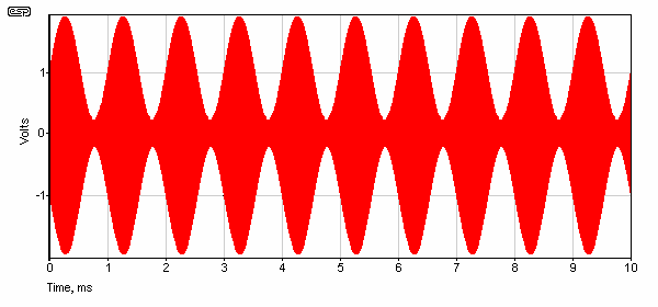
Figure 1 - Amplitude Modulation Waveform
The amplitude modulation waveform is shown in Figure 1. Maximum modulation level occurs when the RF signal falls to zero (maximum negative modulation), or is doubled (maximum positive modulation). Practical limitations mean that the minimum is usually around 5-10% of the static (unmodulated) RF power to prevent 'splatter' - a form of RF distortion that causes massive interference across the radio frequency spectrum. The maximum can be up to 150% of static power, and phase switching is often used to ensure that the highest level signals always increase transmitter power. This is possible because audio waveforms can be highly asymmetrical. The audio signal is always compressed and limited to ensure that over-modulation cannot occur.
Germanium diodes are considered mandatory in this service due to their low turn on voltage and consequent good sensitivity to weak RF signals. Although true germanium diodes are still being made, many electronics parts stores are now stocking germanium diode 'equivalents', diodes that are actually silicon Schottky (hot carrier) diodes, fabricated to electrically resemble germanium diodes as sensitive RF detectors. They are actually pretty good. As with all silicon Schottky diodes, they exhibit very little reverse leakage, very good weak signal sensitivity and low noise. They do possess a higher junction capacitance than most point contact germanium diodes, but this is not a problem in crystal set service. In a moderate to strong signal strength area, a simple diode detector of this type will work well. Combined with optimal diode loading and a selective tuned circuit front end, this kind of approach will indeed work well and provide a high quality audio program source for AM reception.
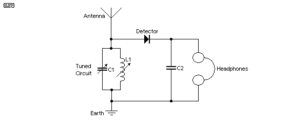
Figure 2 - Traditional Crystal Set Demodulator
Figure 2 shows the general arrangement of a 'traditional' crystal set. As shown, both the tuning coil and capacitor are variable, although many different arrangements have been used. Some sets used variable capacitance and a tapped coil, others a fixed capacitance and a variable coil. Still others used an RF transformer (so L1 has an additional winding) to create a better impedance match between the antenna (aerial) and headphones. Piezo-electric ear pieces were commonly used because of high sensitivity and impedance. The audio signal can be taken to an amplifier rather than headphones.
The need for a selective front end and optimal diode loading are rather important. The relatively low impedance of the diode detector circuit will invariably heavily load its feeding tuned circuit, something which can cause problems such as station overlap and generally poor station selectivity in tuning. My preferred approach is to use double tuning, where using two separately tuned and coupled networks results in much improved 'nose and skirt' selectivity. This does complicate the design admittedly, but the overall selectivity improvement is definitely worthwhile. With single coil tuned circuit arrangements, a commonly used approach is to use coil taps in order to reduce the loading problems by connecting the diode and antenna to a point on the coil of lower impedance. This approach can work well, but it is not quite as good as two separately tuned networks in practice.
The diode loading aspect is actually a rather complex subject, but basically, the ratio of the AC and DC load on the diode output should be approximately equal for the best handling of high modulation depth with minimal detector distortion. This normally means a relatively low value diode load resistor, followed by minimal capacitive shunting as would invariably be needed for RF filtering purposes. A very high impedance for the following audio preamp helps too. A following audio stage impedance of at least 250k is considered optimum. Actually, it is interesting to note that in these modern days of solid state technology, we are actually at some definite disadvantage as lower circuit impedances are generally the order of the day. Valve audio preamps of the past routinely possessed input impedances of the nominal required value.
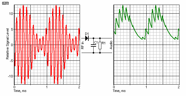
Figure 3 - Demodulation Waveform
The demodulation waveform is shown above. This assumes an ideal (or 'perfect') rectifier - i.e. a diode with no forward voltage drop, no resistance, and no junction capacitance). Because all of these parameters are included free with real components, an alternative diode demodulator is shown below. The RF waveform is shown on the left, but the carrier frequency is reduced to the minimum for clarity.
After passing through the diode, C1 integrates the signal. The cap charges and discharges slightly with each positive-going RF signal, and the remaining signal is the audio. It is always important that the capacitor value is worked out to be correct for the following load resistance (R1). If it is too large, that will create distortion - even if the diode is perfect. This is visible in Figure 3 at the negative-going audio peaks. If too small, excessive RF is applied to the following stage(s).
Note the DC offset in the demodulated audio signal. This is used in superheterodyne (and some early TRF - tuned radio frequency) receivers to activate AGC (automatic gain control) of the RF stage(s) to ensure maximum RF level without excessive distortion.
Listening tests and evaluations show that proper diode buffering makes a very audible difference in a high quality AM tuner application. It is worth noting that diode detectors like to work with a moderate to strong level of RF input, and audible distortion does increase somewhat at lower signal levels. I have developed a novel method of using adjustable voltage bias with a 1N5711 UHF mixer hot carrier diode that does provide improved performance at lower RF signal strengths. This biased diode detector has an incredible ability to produce clean detection under even the weakest signal strength conditions by careful adjustment of the bias potentiometer! As an aside, it must be mentioned that the subject of diode detector distortion is a complex one, and much more involved than one might think. It is gratifying though, that good results can be obtained with simple circuitry.
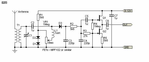
Figure 4 - Improved Diode Detector
Based on some simulations that ESP did with the circuits, a biased detector can reduce distortion from around 6% to 1% with a strong signal, with potentially greater improvements at lower levels. As noted though, this is a complex issue, and not one that lends itself well to simulation - unless the simulator is optimised for RF analysis. Most are not.
However one doesn't have to use a diode type of AM detector. There are other ways to achieve high quality AM detection. I have investigated a number of bipolar transistor and field effect transistor circuits that offer excellent general performance and other advantages as well. The 'infinite impedance' detector, using a field effect transistor is a personal favourite. It is based on a very old triode valve circuit from the early days of 'wireless'. FETs (Field Effect Transistors) are remarkable devices, especially in RF applications, and their close electrical similarity to valves is a very useful characteristic indeed. A FET version of the infinite impedance detector is easily made, and offers very high quality AM detector performance. A particular advantage results from the very high gate impedance of the FET into which the tuned circuit is fed. This effectively eliminates the selectivity problems caused by diode detectors. I have used single tuned arrangements combined with infinite impedance detectors with excellent results in terms of good selectivity. Such is the advantage of a very high input impedance.
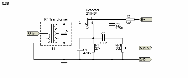
Figure 5 - FET Based Infinite Impedance Detector
A basic 'infinite impedance' detector is shown in Figure 5. While this will work very well, there are some refinements that improve performance. In my set-up, I make use of a high input impedance FET source follower modified with another FET constant current source for improved linearity and lower distortion. The second stage acts as a buffer between the detector and audio preamp input.
The version of the infinite impedance detector I have developed was adapted from the generic circuit that has appeared for many years in the ARRL Handbook, a long available and well regarded text, well known to Ham Radio operators all over the world. The circuit I've developed is more suited to tuner applications, and differs from the basic generic circuit in that the value of the source resistor is much higher, which overcomes a slight tendency to intermittent oscillation, has improved RF filtering, and includes a modified FET source follower output stage for improved audio drive into a following audio preamp stage.
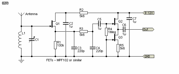
Figure 6 - Improved Infinite Impedance Detector
All round, the field effect transistor based infinite impedance detector is pretty amazing, offering high audio output, low distortion, excellent sensitivity and is quite free of the weak signal diode detector distortion tendency. It offers impressive performance for such a simple circuit. Just connect a tuned circuit and audio system, and one has quite a high quality AM program source.
All of these AM detector circuits offer potentially excellent recovered audio quality, limited only by the quality of the original audio modulation. The infinite impedance detector offers the overall advantage of simple 'no fuss or adjustment needed' apart from tuning, but the biased diode detector has the advantage, by virtue of precise bias adjustment, of coping with any signal strength situation (strong or weak). This does require that the bias be individually optimised for each station received which can be a trifle annoying! However the audio quality under ideal bias adjustment has to be heard to be believed! Also as discussed earlier, due to selectivity considerations, a more complex 'double tuned' input is considered desirable, however another option is to add a FET stage in front of the diode detector in order to relax potential selectivity concerns (as discussed previously). So many possibilities!
Welcome to the wonderful world of building things at work at radio frequencies (RF)! Those who've only dabbled with audio gear will be slightly shocked by the way things are done at RF. It's basically a different world. At times, I've even wondered if Ohms Law applies at RF! At broadcast band medium wave RF, things aren't too critical, but it still pays to do things the right way. At RF, the effects of stray and 'incidental' inductance and capacitance become an important factor. Even a short piece of wire represents a substantial amount of inductive reactance at RF.
XL = 2π × F × L ... and ...
XC = 1 / 2π × F × C ... then we get ...
fo = 1 / ( 2π × √ L × C )
Where XL = Inductive Reactance, XC = Capacitive Reactance, F = Frequency, fo = Resonant Frequency, L = Inductance and C = Capacitance
Things like excessively long leads are a no-no at radio frequencies - you will get around 5-6nH of inductance for each 10mm (1cm) of straight wire, depending on lead spacing and many other factors. My favourite method of construction is using a piece of copper clad circuit board material and wiring all components 'point to point' with all earth (ground) connections going directly to the copper surface of the circuit board material which provides a low impedance ground plane. Veroboard or similar is also quite ok at lower radio frequencies if used appropriately.
Pre-wound coils and ferrite rods can be purchased from the usual parts shops, along with suitable variable capacitors with a maximum capacitance of about 260 pF. The two outer leads of the variable capacitor need to be joined together in common to obtain maximum capacitance. I prefer to wind my own coils in the interest of optimising coil Q (or coil quality). This is a very complex subject in itself, and many differing winding approaches are used, including the use of so-called Litz wire. I use ordinary enamelled copper winding wire of about 0.315 mm thickness, along with spaced turns, where a slight gap (about a wire thickness) is placed between each turn. This helps with coil Q. A drop of super glue adhesive at the start and end of a winding is perfect for stopping a coil from unwinding itself. For the MW band, about 50 turns on a ferrite rod will be needed, however the exact number of turns may vary somewhat depending on local conditions and the desired tuning range.
For simple crystal set type of AM tuners, unless one lives close to a local transmitter, some kind of external antenna and earth connection will likely be required (just like in the old days). Remember that a simple crystal set tuner is a purely passive detector arrangement without any additional active front end RF gain, and the diode detector needs all the help it can get, hence the need for an external antenna. Depending on the method of connection to the tuned circuit, the antenna can affect the tuning range of the tuned circuit. With simple receivers like these, external factors can have a big impact. Remember too that the audio output level is entirely dependent on the incoming RF input level. A lot of empirical adjustment may be needed, but that's half the fun. An earth connection is also needed, but sometimes existing earthing through the audio gear is sufficient. I have an earth rod driven into the ground outside my window in the garden outside with a short connecting lead.
Individual construction arrangement techniques are left up to the constructor, but remember the general guidelines when working with RF circuitry and also try to leave a little space around the coil(s) from any metal (enclosure etc.) in the interests of not degrading the coil Q. Very importantly, when working with any type of external antenna, safety is absolutely paramount! I spent nearly four months in hospital after a serious accident when I fell from a roof, and I live with permanent spinal cord injury as a result. Don't repeat my mistake!
Despite the limitations of this kind of approach to wideband AM reception, I personally have found this a very satisfying way to listen to local AM stations with the sort of audio quality that no ordinary receiver can match. In fact, one may realise that your local AM radio station may have some transmission problem such as distortion or other defect. Such is the potential resolution of this kind of AM tuner. It is rather sad that many transmission defects will go completely unnoticed when listening on an average receiver with a poor audio bandwidth and lots of inherent circuit noise and distortion but are immediately noticed when listening on a high resolution system such as these AM detectors provide! In any case, once you listen to true wideband AM audio you will never think of AM in the same old way ever again!
Unfortunately, the range of available JFETs has shrunk alarmingly since this article was published. The JFETs suggested aren't available from most suppliers, and where they are available, no-one knows for how long (particularly in the TO-92 through-hole package). If you are willing to play with SMD parts, the availability might be a little better, but the MPF102 is listed as obsolete.
A few suppliers still offer them, and likewise the 2N5484, but you may need to be prepared to grab a few when you find them, as they aren't common any more. You also need to have a few more than expected, because JFETs have a wide parameter spread, and you usually have to run tests so you can find ones that will work in the circuits. I suggest that anyone interested in the circuits here read the Designing With JFETs article, which has a lot of information that you'll find useful. This includes a simple circuit you can use to determine that two main parameters of interest, the 'pinch-off' voltage (VGS(off) and the zero gate voltage drain current (IDSS).
 Main Index
 Articles Index