
|
|
| Elliott Sound Products | AN-017 |
 Main Index
App. Notes Index Main Index
App. Notes Index
|
The most common use for DC detection circuits is to protect loudspeakers from a faulty amplifier. The general principle is little different from a zero crossing detector (see AN-005), and indeed, an (almost) identical circuit can be used. The difference is that a zero crossing detector is intended to detect the zero voltage condition in 'real time', whereas a DC detector must have a high pass filter so the circuit doesn't trigger on low frequency, high amplitude signals.
The filter is the thing that causes the greatest difficulty, because it is normally a fairly high impedance to keep the required capacitance low. Because the input can swing either positive or negative with different fault conditions, the capacitor can't be a conventional (polarised) electrolytic, because it may be subjected to a fairly high reverse voltage which will damage the cap.
In Project 33, the input resistor is 100k, and the cap is 10µF, giving a low frequency -3dB frequency of 0.159Hz. While this may seem way too low, it's actually right for most amplifiers of 60W (8 ohms) or more. A higher frequency would mean that low frequency signals can easily cause the protection relay to chatter, introducing gross distortion.
Because the impedance is so high, the available current is low, and this generally precludes the use of an optocoupler. While it's not impossible (far from it in fact), the impedances all need to be reduced so the optocoupler gets enough current to be useful. This means that a fairly large capacitance is necessary, but it doesn't need to be high voltage (6.3V will normally be sufficient).
There is (or was) an IC (µPC1237HA) designed specifically for the purpose of DC detection, and (at least in theory) it required few external parts. However, the application circuit set a dangerous precedent by wiring the speaker relay incorrectly, and the same error has been repeated ad nauseum in most DC protection circuits that have been published over the years.
While it seems like a good idea to use an IC designed for the purpose, there are easier ways to achieve the same results, using readily available, cheap transistors and diodes (plus a few passive components). The advantage of the latter approach is that suitable replacement parts will be available forever, so a failure doesn't render the PCB useless scrap.
The relay wiring is something that requires some explanation. It's an exercise in futility to expect a relay rated for 30V DC (the typical maximum rating) to break an arc created by an amplifier using ±45V supplies or more. Even the default 30V relay will arc with 30V, and the arc current is transferred to the speaker. The solution is to wire the relay so that when off, the loudspeaker terminal is grounded. Even if (when) the relay draws an arc, the current is bypassed to ground, and the loudspeaker is protected. The relay may be destroyed, but relays are far cheaper than loudspeaker drivers, so it becomes a sacrificial component - it dies to save your speakers. That's a reasonable trade-off in my books.
This app note discusses the various options that can be used to detect DC if it turns up in places where it should not be (such as at the output of a power amplifier). All test waveforms shown use a 100k input resistor, and are shown with a 1Hz signal with a 10V peak to peak amplitude. In each case, the supply voltage is 12V DC, and the presence of DC is indicated by a zero output voltage. The high pass filter is deliberately omitted so the instantaneous action of the circuits can be seen.
Outputs are simulated, but I know from tests that I've run that the simulated and bench tested versions are virtually identical. These circuits can all be considered window comparators. Provided the signal is within the defined voltage 'window' the output voltage is low, and rises to 12V (or thereabouts) when the voltage is above or below the set values.
Note that the input voltage (1Hz, 5V peak) is offset by 6V so the detection points are immediately visible. Each circuit is shown with an AC voltage as the input, but that's for analysis purposes. In what's laughingly referred to as 'real life' (  ), the generator is replaced by the power amplifier output, via a filter to prevent activation with the audio waveform. All circuits shown are assumed to use a +12V supply.
The principle of a DC detector is very similar to a zero-crossing detector (ZCD - see AN-005). When the DC input voltage is close to zero the relay is energised and allows the amp's output to be connected to the speakers, but if it exceeds the preset limits the relayi s turned off. Several of the ZCD circuits are potentially suitable for DC offset detection, but the overall requirements are actually quite different, despite initial appearances. All DC protection schemes rely on a filter to remove the audio component down to the lowest frequency of interest. This is disabled for analysis, but is essential in normal use.
Of the various techniques, the only ones I will not cover is the µPC1237, plus a few others as noted. The IC is obsolete, and its internals are not disclosed in such a way that it can be analysed properly without having one to hand. There are several other techniques that I haven't covered, either because they won't work or require an isolated power supply in order to function as designed. This includes various circuits that use a bridge rectifier at the input, which will certainly work, but it will only work properly if a floating 12V supply is available. This makes the circuit a nuisance to power. I've also left out any system that requires a dual power supply, because that just makes the circuit harder to build because a simple +12V supply can't be used.
The others vary widely, and one was suggested by a reader. This is a good circuit, and it's fairly easy to make it work with two amplifier inputs. One that is also worth looking at is Project 175, which is designed for use with BTL (bridge-tied load) power amplifiers. All circuits are shown for a single channel only, and do not include the high-pass filter. This was done so that the input and output can be viewed with a standardised input voltage and frequency.
Please note that the input AC signal is offset by 6V so positive and negative transitions can be seen easily. That means that the reference (zero volt) level for the AC waveforms shown below is 6V, and not zero volts. This is indicated on the right of each response graph.
The first method examined is the one that's used in Project 33. It's very effective, but it is slightly asymmetrical. This means that the detection thresholds are different depending on whether the DC fault is positive or negative. In reality, this makes absolutely no difference, because power amplifiers rarely (if ever) develop a fault that causes a DC offset that is other than one or the other supply rail (basically, I've never seen it happen, nor have I heard of it happening, other than if a preamp goes bad and there's no coupling capacitor in place).
A positive Input voltage causes the voltage at the base of Q1 to rise, turning it on. A negative input pulls the emitter voltage low, which also turns on Q1. Q1 operates in common emitter mode for positive voltages, and common base mode for a negative input. R2, R3 and D3 ensure that sensitivity is roughly the same regardless of how the transistor is driven (i.e. with positive or negative inputs). The remaining transistors increase the small current available from Q1 into something suitable for driving a relay (wired in place of R8).
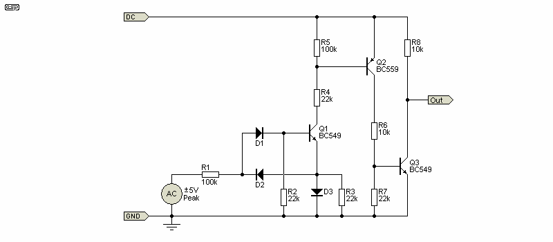
Figure 1 - P33 DC Detector
Because this circuit uses diodes at the input, it's easy to add more channels simply by adding extra diodes (along with a filter circuit of course). This circuit was devised many years ago, and it only requires a single supply. The PCB also includes a 'loss of AC' detector, which mutes the amplifier almost instantly when power is turned off. It also includes a power-on mute, but the detector shown above doesn't include these.
The threshold for positive input is 3.46V, and for negative inputs it's -3.39V. This variation is inconsequential in reality, and both thresholds are within the 'safe' range for most loudspeakers (less than 2W for an 8 ohm speaker). Because all DC detector circuits disconnect the amplifier from the speaker when the threshold it reached, no damage will be caused.
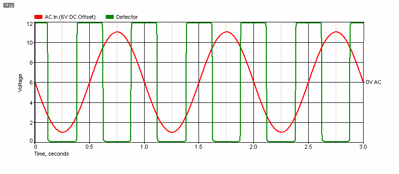
Figure 2 - Voltage Waveforms
The output waveform has clean transitions, and there's no sign of anything that may raise a 'red flag'. This circuit has been used by (literally) hundreds of constructors, and I've never heard of a failure. Additional channels require duplication of the input resistor (and capacitor, not shown) and the input diodes.
The next option is one that was suggested by a reader. Its detection thresholds are fairly symmetrical, but it is very sensitive. The sensitivity can be reduced by including R2, but when that's not included it will trigger at less than ±1.8V. Including R2 reduces sensitivity. As shown, the detection thresholds are +1.25V and -1.77V.
A positive Input voltage causes the voltage at the base of Q2 to rise, turning it on. A negative input causes the base of Q1 to fall, turning it on. Either case results in the removal of base current for Q3, which turns off. The relay can be wired in series with the collector of Q2. The remaining transistor was included to reverse the polarity and increase the overall gain.
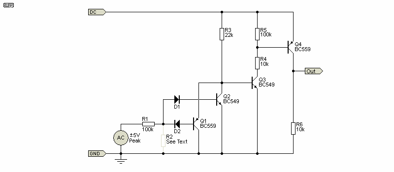
Figure 3 - 'Mitko' DC Detector [ 3 ]
This is a nice, simple circuit, and by adding input diodes more than one channel can be accommodated. There is an additional transistor included in the circuit to ensure the same polarity as the others shown, but in reality, Q3 can drive a relay directly from its collector circuit.
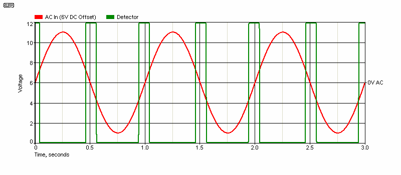
Figure 4 - Voltage Waveforms
The waveform is very clean, and the high sensitivity is quite obvious. I would have no hesitation recommending this arrangement, but it's a little harder to add a power-on mute and/ or 'loss of AC' detector as used in the Project 33 circuit board. The sensitivity can be reduced simply by adding a resistor (R2 'See Text'). If R2 is made (say) 56k, the thresholds are raised to ±3V, which is a perfectly reasonable voltage.
Additional channels can be accommodated by duplicating the input resistor (and capacitor, which is not shown here), as well as the two diodes. Sensitivity is unchanged, and extra channels work identically. There are basically no downsides to this approach.
This is a particularly good arrangement, which is almost perfectly symmetrical provided R1 and R2 are the same value. While it appears more complex, it's still a very simple circuit to build, and it's based on a conventional window comparator circuit. The diodes can be eliminated if the LM358 is replaced by a dual comparator (such as the LM393).
A positive input forces Pins 2 & 5 of U1 to rise. When the voltage at Pin 2 exceeds that on Pin 3, the output (Pin 1) goes low, and pulls the output voltage to (near) zero. A negative input voltage forces Pin 5 to a lower voltage than Pin 6, causing the output (Pin 7) low. The two diodes prevent the opamp outputs from interacting (they cannot be omitted, unless the opamp is replaced by a dual comparator.
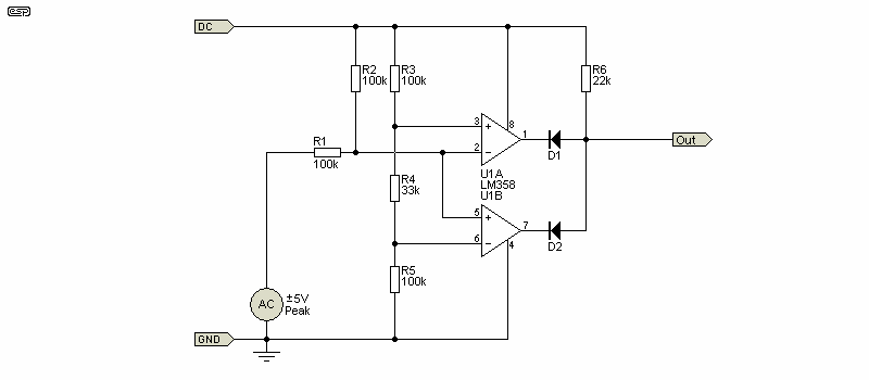
Figure 5 - Opamp Based Detector
The detection thresholds are easily adjusted simply by changing the value of R4. With 33k as shown, the thresholds are +1.68V and -1.72V. The resistor string (R3, R4 and R5) can be reduced or increased in value, and provided the relative values are the same, the thresholds are unaffected. Because of the way it operates, R2 is required so that the input voltage is exactly half the supply voltage.
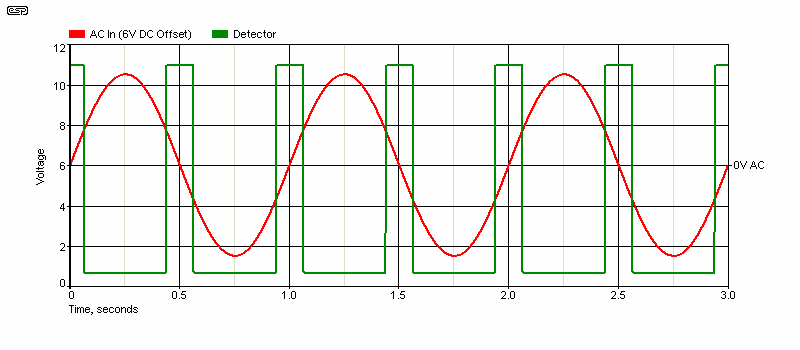
Figure 6 - Voltage Waveforms
While this circuit is very sensitive as shown, that's easily adjusted simply by increasing the value of R4. For example, if R4 were to be 100k, the thresholds are ±4V (You may expect a higher voltage, because the 'pull-up' resistor (R2) forms a voltage divider). However, it really is ±4V. Unlike most others, it can be made to be far more sensitive, simply by reducing the value of R4. At 10k, the thresholds are ±580mV.
If used for stereo, only the opamps, diodes and input circuits need to be duplicated. The voltage divider (R3, R4 and R5) can supply the reference voltages to both channels. While this is the most elegant (and predictable) solution, it's also more expensive to build and takes up more PCB real estate.
The next circuit was used by a major home hi-fi manufacturer (which shall remain nameless because the circuit is rather poorly thought out). The positive threshold is 2.81V, but the negative threshold is poorly defined and has a low output level. The best estimate is around -4.33V, so it's very asymmetrical. It can be argued that the negative detection threshold is really -3.81V, but that doesn't really help. Note that the output polarity is reversed in this circuit - it's at some positive voltage when the DC thresholds are exceeded. The other circuits show a positive voltage when there is no significant DC voltage.
When the input goes positive, Q1 turns on, and that removes the drive current to Q3 (which uses a zener diode as a level shifter in its base circuit). A negative input voltage is intended to turn on Q2, which is connected in a common base configuration. Unfortunately, this doesn't work as well as expected, because the common base configuration means that the emitter current is the sum of the base and collector currents. Negative detection is therefore rather dismal. It's worth noting the the Figure 1 circuit also uses common base connection for negative voltages, but it's been designed to ensure equal sensitivity in both common emitter and common base modes. Since no such precautions were taken in this circuit, it doesn't work well at all.
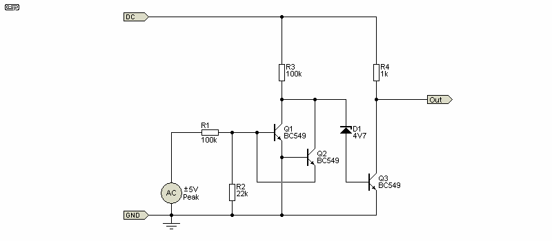
Figure 7 - Commercial Detector
The negative detection is so poor that additional amplification would be essential to ensure that a relay will activate reliably at the detection thresholds. As shown, it will activate a relay without additional parts, but the negative DC voltage needs to be at least -10V to ensure reliable relay operation. This is not a circuit I could ever recommend, and it's shown purely because it exists in a commercial product. Many people think that major manufacturers know what they are doing, but often they only aim for 'good enough'. This arrangement can be modified to work much better than it does simply by adding a couple of resistors, but IMO there's no point pursuing it. It's also unsuitable for more than one channel, which is another limitation.
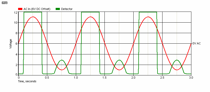
Figure 8 - Voltage Waveforms
In a word, "dreadful". This isn't a circuit I'd use or recommend as shown, because it's symmetry is so poor. Yes, it will (probably) protect loudspeakers from a failed amplifier, but it's not an elegant solution by any stretch of the imagination. However, it can be improved, and it's not particularly difficult to do so. The problem with the circuit lies in the third transistor (Q3) and the zener diode, a combination that's very poorly thought out.
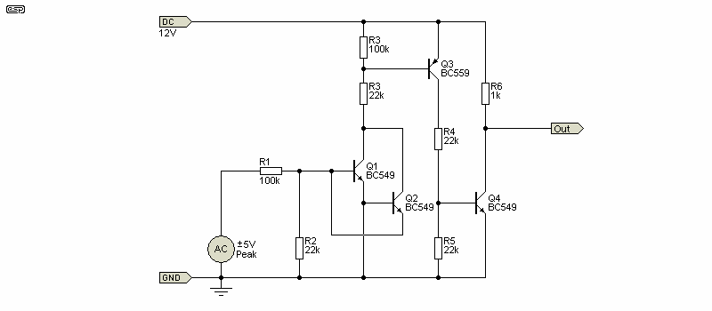
Figure 9 - Improved Commercial Detector
With the addition of one transistor and a couple of resistors, the circuit becomes usable. The detection thresholds are +2.4V and -3.3V with the values shown. The output waveform is much closer to those shown in Figures 2, 4 and 6, rather than the appalling waveform in Fig. 8. The cost difference is marginal, and you get a detector that works as it should.
With the exception of Fig. 5 (using opamps or comparators), all of the detection schemes are asymmetrical. It doesn't really matter, because when an amp fails the output voltage is well above the detection thresholds. However, it's probably still perplexing because you need to understand exactly what's going on to understand why the threshold voltages aren't the same for positive and negative fault voltages.
This comes about because many detectors use base drive for positive inputs, and emitter drive when the input signal is negative. Unfortunately, the transistor that uses emitter drive has no current gain, so the collector current is (almost) the same as the emitter current. If you have (say) 5V across a 100k resistor, the current is 50µA. This is more than enough base current to drive a transistor (common emitter) into saturation, but if the collector resistor is 22k, the voltage drop across it with emitter drive (common base) is only 1.1V (vs. [say] 12V when the base is driven).
That's a big difference, so the next transistor needs a lot of gain to saturate (turn on completely) with only 50µA base current. The original circuit in Fig. 7 doesn't have anywhere near enough gain (and it's badly configured), so performance is limited. In the other circuits, the required gain is available, but because the collector current in the detector is so asymmetrical, the detection voltage is also asymmetrical. Even when NPN and PNP transistors are used, that still doesn't mean that the circuit will be symmetrical. No two transistors of opposite polarities will ever be identical.
Asymmetry can be cured completely by using a dual supply - say ±12V. However, that means a more complex power supply which will cost more. If (when?) a power amplifier fails, it's almost always due to a shorted output transistor. There are exceptions of course, but nearly all failures mean that the amp's output voltage swings to one supply rail or the other. 'Partial' failures are certainly possible, but are very rare (I don't think I've ever seen a failed amp where the quiescent output voltage was not stuck to one supply rail or the other).
Use of DC coupled amplifiers is discouraged (by me) because they don't make sense for audio. A fault in a preamp can cause the amp's input to be subjected to some indeterminate DC level, which is then amplified. If the DC input is around 100mV, you could get a DC output from a DC-coupled power amp of perhaps 3V, and that will not trip 99% of DC detectors. It also won't hurt most speakers, but it will cause a significant cone offset, increasing distortion.
All of the circuits shown need an input capacitor as shown below. They were omitted from the circuits so the detection voltage could be monitored, but they are absolutely essential in the final circuit. The cap needs to be large enough to ensure that a full power 20Hz audio signal will never trigger the relay. In most cases, a 10µF bipolar electrolytic capacitor will be sufficient, but if the detector is very sensitive a larger value may be necessary. The input resistance/ impedance of the detector needs to be considered (not shown in Figure 10), but it's usually not a major issue.
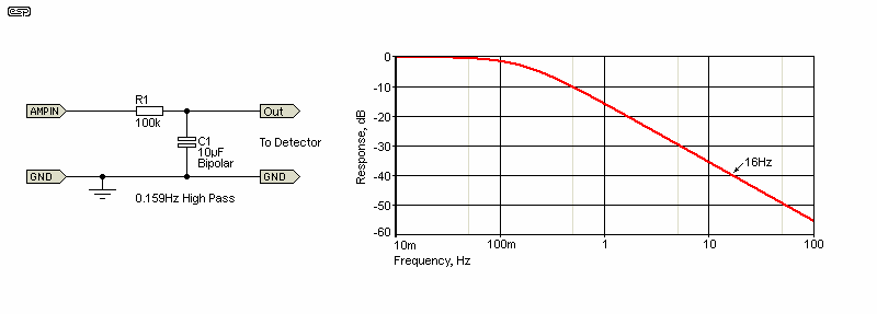
Figure 10 - Input Filter (Typical)
The filter isn't particularly critical, with the main proviso being that no normal audio signal should cause the detector to trigger. The criterion I used for P33 was that a signal of 50V RMS at 16Hz should not cause the circuit to 'false trigger'. The same level at 10Hz should cause the protection relay to operate, ensuring that the amp's output is disconnected quickly enough to ensure that speaker damage won't occur. With amplifiers having a greater output capability (or detectors with a low input impedance), the capacitor value may need to be increased.
The figure of 16Hz was used because that's the lowest frequency normally available from large pipe organs, and it's extremely unlikely that such a high level will ever be present in any recorded material. The filter shown is -40dB at 16Hz, which is ideal. Should a DC fault develop, the response time is dependent on the fault voltage, and with 35V (positive or negative) the circuit will respond in under 40 milliseconds. Most relays will release in less than 10ms, so the worst case is that the loudspeaker will be subjected to the supply voltage for no more than 50ms (an energy level of under 8 Joules ¹). This is not sufficient time or energy for any damage to occur with woofers, but for tweeters the cutoff frequency needs to be raised to provide faster operation.
¹ 8 Joules is delivered from a 10,000µF capacitor charged to 40V. If this is delivered to any typical low-frequency driver the result is no more than a loud 'pop'. No damage will occur, as the energy is not present for long enough to cause voicecoil heating.
Of the circuits shown, those with diode inputs can be adapted for stereo by adding another pair of diodes and a second filter circuit. If diodes are not used, the circuit needs to be duplicated for stereo operation. While it is possible to simply add a second input resistor, this will only work with the Figure 5 circuit (for example) if R2 is reduced to half the value shown (50k). Adding the second input resistor has the secondary effect of reducing the sensitivity, so the circuit won't be as fast. More troubling is that if one amp output goes positive and the other goes negative, the two cancel and the circuit won't react at all.
While this is extremely unlikely (the faults would have to be simultaneous), no protection is offered at all if the amp is turned off and back on again with the faults still present. The chances of such a failure may be extremely small, but it's not a risk I'd be willing to take. A protection circuit that doesn't work when it's needed is dangerous, so The Figure 5 circuit would require duplication to ensure ultimate reliability. The Figure 7 circuit is not recommended at all, and it's shown solely because it exists, and you may come across it one day.
There are several alternative speaker protection circuits, with many based on principles that are similar to those shown here. Some can be expected to work, but others are likely to be somewhat irrational approaches to the problem. Some have been thought through, while a few examples appear to have (potentially serious) flaws. I have neither the time nor inclination to even try to include all of the arrangements I've seen, but almost without exception, the 'protection' relay is wired incorrectly, without the normally closed terminal grounded. The amplifier should always be connected to the common terminal of the relay, with the speaker connected to the normally open contact.
BTL (bridge tied load) amplifiers pose special problems, especially those that use a single supply. That means that each speaker terminal always has DC present. One solution to this dilemma is described in Project 175, which uses the method shown in Figure 5. It shows LM393 comparators rather than opamps, but the principle is relatively unchanged. There is some added complexity because you can't rely on the output voltage being exactly half the supply voltage.
There is one (and only one) way to wire the relay, and that's shown below. The vast majority of speaker 'protection' circuits simply wire the amplifier and speakers to the common ('Com') and normally open ('NO') contacts, and if the voltage is over the rated maximum for the relay (typically 30V DC), when the contacts open an arc will be drawn across the contacts, which passes DC straight through to the speakers. I see many, many circuits published that completely fail to address this, so the protection circuit may actually provide far less protection than you imagine. I've tested and verified this!

Figure 11 - Relay Wiring Diagram
The drawing shows the correct wiring. If (or when) an amplifier fails, the arc current is shunted to ground rather than the speaker. In some cases, a capacitor can be used in parallel with the contacts in the hope that it may suppress the arc, but it needs to be a fairly high value, and there's absolutely no guarantee that it will work. You can also use two relays, with the contacts wired in series, which gives a theoretical maximum voltage of 60V DC. This is covered in some detail in the Relays, Part II article. Failure to configure the relay correctly could become a very costly mistake, especially with very high power amplifiers. The problem is worse with single-supply BTL amplifiers because you can't short the speaker to ground, so see Project 175 for details.
| Main Index
App. Notes Index
|