

|
| Elliott Sound Products | Project 83 |
I have been trying for years to find high quality solution for power audio amplifier. I have tried valves (vacuum tubes), bipolar transistors, MOSFETs, Class-B, AB, A push-pull, A single-ended ... you know what stuff I speak about.
Nelson Pass describes those terms perfectly (see www.passlabs.com). He also describes why he prefers the solution of single-ended Class-A MOSFET power stage with common Source. I think that his thoughts can be broadened even more. From my point of view a power MOSFET follower is a still better solution. It has benefits of single-ended class A amplifiers with common Source plus something more - less distortion, lower output impedance, higher input resistance and ... no feedback.
With one drawback - voltage gain is only +1 ¹, so it needs preamplifier able to deliver up to 12V RMS. The sound impression is perfect, surpassing the common Source MOSFET circuit. You can see schematic that I have tested in Fig.1.
¹ The actual voltage gain is in fact 0.98 (for RL=8 Ω), as the IRF350 MOSFET transconductance is 6 Siemens [1/Ω] and therefore ...
Gain = 6 / (6 + 1 / 8) = 0.979
Measurement gave the same number.
The circuit consists of an N-Channel MOSFET voltage follower (common Drain) and current source (NPN Darlington). The current source is set to 2.2 Amps. With 40V of supply voltage the circuit is able to deliver about 17W into an 8Ω loudspeaker. The amplifier will take 88W from the power supply all the time. VR1 is used to set symmetrical clipping. Ideally, this would be done with a speaker connected, but it will be too loud. A dummy load will work well enough.
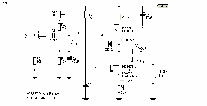
Figure 1 - MOSFET Power Follower
Bandwidth (-3dB) is from 4Hz to 250kHz. Rise time is 1.5µs. Output resistance 0.16Ω. The circuit is very tolerant of different kinds of load. Input resistance is 10 kΩ (R0), but can be increased up to 100k (R4) by omitting R0. Input capacitance remains relatively high, about 1,500pF. For this reason, the preamp should not have higher output impedance than 1k to maintain high frequency limit about 100kHz. An input potentiometer can be used instead of R0.
The drawings shown are slightly different from Pavel's original. A fixed resistor has been used for the zener feed, and I made a couple of minor changes so the schematic was more like my standard style.
If the value of the potentiometer is 5kΩ then the high frequency limit will be about 70 kHz. The power follower can be connected directly to the output of CD player, and for reduction of volume potentiometer 5kΩ can be used. As a preamplifier you may use Nelson Pass's projects 'Bride of Zen' or 'Balanced Line Stage' (see passlabs.com).
Note: The original (single supply) DoZ preamp will also drive this amplifier well, especially if the supply voltage is increased slightly. Although it is specified for +30V, it will operate quite happily at up to +40V. It may also be possible to direct couple the preamp's output to the power follower - omit R0, R2, R3, R4, C1 and C2 - as well as the output capacitor on the preamp. Needless to say, this would be my recommendation as the ideal preamp for Pavel's circuit - especially with direct coupling (see below). There are some changes needed to use the latest revision of the DoZ preamp, because it uses dual power supplies. More info below.
How does it sound? Wonderful, regardless low or high volume. Entire spectrum from bass to high is perfect. It only needs a good preamplifier.
I have tested an amp for a considerable amount of time and there was never problem with thermal runaway. Normally, the thermal coefficient of zener voltage of 3V type is negative, and so is V-be voltage of the Darlington transistor. As V-be is reduced by -2mV/°C, zener voltage also goes down with increasing temperature inside a box (but the zener is not on the heat sink of the MOSFET and should not be). In fact there was a fluctuation of 40mA at 2A constant current, from my point of view it is negligible. Of course the heatsink for T1 and T2 should be better than 0.5°C/W for each transistor, so four such heatsinks are needed for stereo.
PROS:
KD367B! - very funny thing. I am from Prague, Czech Republic. The KD367B is a product of the former TESLA of Czechoslovakia, now they are a part of Motorola and these transistors are not produced any more ... TIP141 or TIP142 will do the same work without any problem.
KD367B's parameters:
NPN Darlington
Ucbo <= 100V
Uceo <= 100V
Ic <= 8A
Ib <= 0.15A
Ptot <= 60W
hFE = 1000 approx.
Rthjc <= 2.1°C/W
fT = 7MHz
TO3 case
Comments: macura@centrum.cz

To get the voltage gain needed for a normal installation, the DoZ preamp can be used. Everyone who has built this circuit has commented on the exceptional sound quality, and it is ideally suited to this application. Pavel has tried the combination, and he says ...
I have already checked the DoZ with the Follower. Both original versions, with caps (not direct coupled). The DoZ being supplied from external 30V power supply. The DoZ and the Follower interconnected by 5kΩ potentiometer. Works perfectly, sounds wonderful.
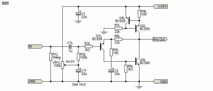
Figure 2 - Original P37 DoZ Preamp as Driver
Figure 2 shows the modified (original single-supply) version of the preamp, the output of which would be connected directly to R1 in Pavel's circuit. The quiescent output voltage is now set by VR1 in the preamp, and the voltage at the source of T1 should be set to 19.8V as shown in Figure 1 by means of VR1 - the voltage at the gate (preamp output) should be 4V higher, i.e. 23.8V. The DoZ preamp board is stereo, and can drive a pair of Pavel's power followers with ease. Q2 and Q3 should be fitted with small 'flag' heatsinks to allow them to dissipate the increased power caused by the higher operating voltage. Note that the current version of the DoZ preamp is normally operated from a split supply (positive and negative supply rails), but it is reasonably easy to modify it as shown above. I will provide full modification details if there is sufficient interest.
As shown, the gain is 3.2, so it will require nearly 4V RMS input for full power. To change the gain, I suggest that R5 be changed to 3k3 to obtain a gain of 7.7 (17.7dB), which will give an input sensitivity of about 1.5V for maximum output. C3 will also need to be changed, and a value of 100µF will be more than adequate. I do not recommend that R4 be reduced to less than 2k7, which will give a gain of 9.15 (19.2dB). To maintain good low frequency response, C2 will need to be about 100µF, although even with 25µF, the low frequency response is maintained to 2Hz. Ideally, the input network should define the low frequency limit, so the higher value is recommended if R5 is reduced. The capacitor marked C* does not normally exist on the PCB, so needs to be added.
Unless a preamp is used in front of the amp, a pot will be needed at the input for gain control. 10k is fine here, and will not cause excessive loading on the source.
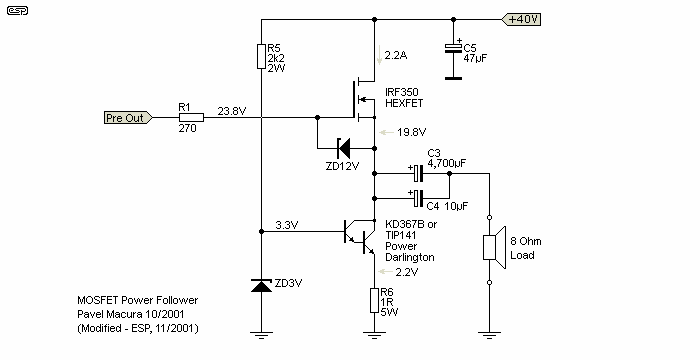
Figure 3 - Power Follower Modified for Direct Coupling
Figure 3 shows what Pavel's amplifier looks like after it is modified for direct coupling to the DoZ preamp. The complete circuit is deceptively simple, but should give a very good account of itself. However, the PCB version of the DoZ preamp is not suitable - see note below.

Please be aware that the current version of the DoZ preamp uses a dual supply (±15V) and it is not suitable for direct coupling to the follower. It can still be used, but the follower needs the biasing network shown in Figure 1. The DoZ preamp can be operated with ±20V supplies so it can drive the follower to full power with a 40V supply. In most cases it will be easier to run the follower from a 30V supply (10W output into 8Ω) and use the standard ±15V supplies for the DoZ preamp.
The amplifier can also be used to drive headphones, and the quiescent current may be reduced considerably. R6 controls the current, and may be increased to 10Ω for use as a headphone amp. This will reduce the current to about 200mA and dramatically reduces the heatsinking requirements. 120Ω resistors should be used in series with the headphone output, and C3 can be reduced to 220µF for a single headphone output, or 470µF for dual outputs (using 2 x 120Ω resistors). Smaller (and cheaper) MOSFETs can be used at the lower power, but they need to be carefully selected to ensure that there is no oscillation (continuous or parasitic).

Figure 4 - Direct Coupled Power Follower Using MOSFET Current Source
A further modification that a reader (thanks Shaan) has tried and tested is shown above. Using IRFP150N MOSFETs as both the amplifier and current source, the problem of finding a suitable Darlington transistor goes away. While the lower MOSFET increases the available voltage swing by a couple of volts, this doesn't make it sound any different or produce any audible power increase. R6 may be a single 0.33Ω resistor, or 3 x 1Ω resistors in parallel. Total dissipation of R6 is 1.6W, so 3 x 1W resistors will work fine. Non-inductive resistors are highly recommended to prevent any possibility of RF oscillation. It may be necessary to reduce the value of R6 to obtain the specified 2.2A quiescent current. Any reduction of resistance will be small - the theoretical resistance for 2.2A is 0.295Ω
The specified IRFP150N MOSFETs are rated at 160W (some IRFP150 devices are rated at up to 230W), and use the TO-247 package so heat transfer to the heatsink is better than average (although not as good as the TO-3 package). It is also a good substitute for the original IRF350, which is very expensive and/or difficult to obtain now. There are differences as one would expect, but these are unlikely to make a great deal of difference to the measured or audible performance.
Note: Do not attempt to use any TO-220 packaged MOSFET, regardless of claimed performance. Heat transfer from the small surface area is not good enough for continuous operation at these power levels (about 44W for each device). The TO-220 package should not be expected to handle more than about 20W continuous power.
While you would expect that a gate 'stopper' resistor would be needed for the lower MOSFET, Shaan tells me that it caused the current source to oscillate. Once removed the circuit behaved itself perfectly and there is no signal degradation cause by the use of the MOSFET. Note that I have not tested this variation, but I expect that it will work without any problems.
Pavel has also sent me his version of the power follower using discrete transistors as the current source. Rather than the Darlington transistor, it uses an MJE15030 driver and MJL21194 power transistor. An extra resistor has been added in series with the gate, as this was found to be necessary under some conditions and with some wiring layouts.
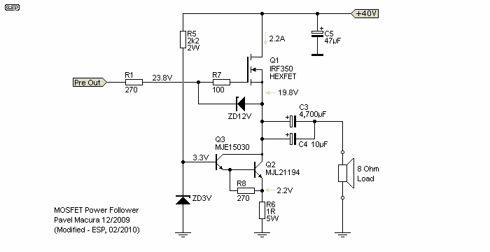
Figure 5 - Pavel's Latest Version Direct Coupled Power Follower
Pavel quotes distortion figures of 0.065% THD at 400mW, rising to 0.43% at 10W output. From a regulated 37.5V supply, you can expect about 30V peak-to-peak into a 10Ω load (about 11W), or 20V p-p into 5Ω (10W).
Note that Pavel specified an 18V zener diode for gate protection, but I suggest 12V. There is no conceivable audio signal that can ever reach more than a couple of volts (usually a great deal less) between the gate and source, and allowing a higher maximum voltage will not improve performance.
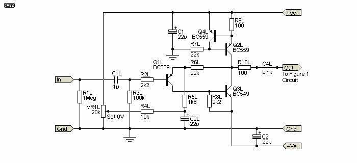
Figure 6 - Latest Version Of P37 (Dual Supply)
The latest version of the P37 (aka DoZ) preamp is the P37 Revision-A board, but without the output coupling caps (C4L/R). They are replaced with a link as shown. As noted above, this version uses a dual supply and cannot be direct-coupled to the MOSFET follower. However, it can be used with the Figure 1 version, which has a biasing network for the MOSFET. This does add a few parts, but They will not adversely affect the performance. If the P37 board is operated from ±15V, output power is reduced, and using more than a 30V supply for the follower won't achieve any more power. Expect about 12W at the onset of clipping. Note the value of R5 (L & R) is 1.8k, which gives a gain of just over 13 (22.4dB). This gives an input sensitivity of 756mV for 10V RMS Output (12.5W).
The power supply options shown in the Project 36 (DoZ) page are suitable, but you will almost certainly have problems getting the required 40V DC. A 30V transformer will come up short (around 34V DC) because of the large non-linear load (4.4A for two channels). A 40V transformer will produce around 46V, which is too high. Total dissipation (each channel) will be around 50W, or 100W for the stereo pair. That's a lot of heat to get rid of, and it requires a very large heatsink.
Since the amp described is intended for low power operation, I suggest that you use a 30V transformer, optionally with the capacitance multiplier shown in the DoZ page. The transformer needs to be at least 300VA, but if you use a larger one you'll get a bit more voltage. Don't skimp on the filter caps, and the two 10,000µF caps shown in the DoZ page should be considered the minimum. At the lower supply voltage, the total dissipation for each channel is reduced to about 40W - that's still a lot of heat to move out of the transistors, and I suggest that you read the Heatsinks article so you know what you're up for.
 Main Index
 Projects Index