
|
| Elliott Sound Products | Project 81 |
 Please Note: PCBs are available for the latest revision of this project. Click the image for details.
This project is essentially an adaptation of the 24dB/Octave L-R crossover featured in Project 09. So much so, that it uses the same (Revision B) PCB, albeit with some components omitted, and a few wire links. For a 12dB crossover to follow the Linkwitz-Riley alignment, a sub-Bessel filter with a Q of 0.5 is used, rather than the more common Q of 0.707, which gives a Butterworth alignment. The Revision B board is very similar to the original, but allows for balanced inputs if desired.
The basic problem with Butterworth crossovers is that they have a 3dB peak at the crossover frequency, and this occurs when the outputs are summed electrically or acoustically. Using a filter with a Q of 0.5 means that the signal is 6dB down at the crossover frequency for both high and low pass sections, and the summed output is absolutely flat.
Version 1.3 of the ESP Linkwitz Riley crossover calculator (88kB) makes short work of determining the component values needed for any frequency. The program is written in Visual Basic, and is not compressed. You may need the VB runtime libraries for this to run - details of how to obtain these are provided in the Project 09 page.
If you have access to a capacitance meter, I suggest that capacitors should be matched to within 1%. Buy more than you need, and select those that are within this tolerance. The remaining caps can be kept for use in another project. 1% metal film resistors are highly recommended, and better opamps can be substituted for the TLO72 devices shown. Bear in mind that there is unlikely to be any sonic improvement by using (for example) OPA2134s in the input buffer or filter stages, since they operate at unity gain, but they are quieter. I suggest that low noise opamps be used in the output sections, as the high pass section operates with gain (6dB), and the low pass section is inverting. Both will add some noise.
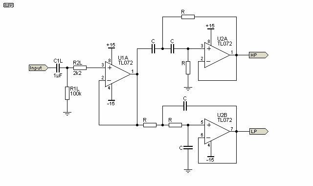
The circuit diagram of the filter section is shown in Figure 1. It is a completely conventional filter, and the component designations are the same as for the 24dB unit described in Project 09. It is designed primarily for 2-way electronically crossed over systems, such as adding a subwoofer or biamping an existing loudspeaker system. In general, the 24dB/ octave version is preferable, but some people do prefer the slower rolloff of the 12dB filters. Note that the resistor and capacitor values are the same - this creates a 'sub-Bessel' filter alignment that's the heart of a Linkwitz-Riley 12dB crossover network.

Figure 1 - 12dB / Octave Crossover Network
Only the left channel is shown - the right channel is identical. As can be seen from Figure 1, there is an input buffer to ensure that the filter networks are driven from a low impedance. This assures an accurate response, and it cannot be omitted. The output of the buffer stage drives the high and low pass sections for each channel. The filters are conventional feedback types, and have very good performance even with budget opamps.
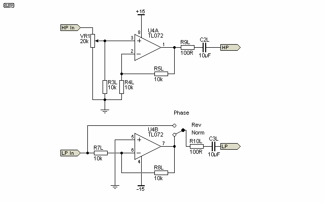
U1B (the second half of the input buffer) is used for the right channel. Note that the latest version of the P09 PCB has provision to wire the input buffer for balanced operation, but it can still be wired for unbalanced as shown above. Figure 2 shows the output buffers - again using the same component designators as the P09, but with some circuit changes. The low pass section is inverted, since 12dB crossovers always invert the phase of one signal. If desired, the high pass section may be inverted instead - see Figure 3 for the alternative version.

Figure 2 - Output Buffers
The above shows the output buffers (again, left channel only) connected in the manner I used for the prototype. The high pass section provides a gain of 6dB, and has a pot to adjust the level to allow for different loudspeaker sensitivities. The gain can be adjusted from +6dB to (close to) zero, which will be more than enough for any installation. The low pass buffer has a gain of -1, which is to say that gain is unity, but inverted. A phase switch can be incorporated as shown to allow for sub-woofer phase correction - this is not needed for a biamp setup.

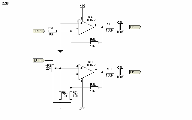
Figure 3 - Output Buffers (Alternative)
Finally, Figure 3 shows the alternative connection for the output buffers. Some builders may find this more to their liking, although for the most part it doesn't make a great deal of difference. This can still have a phase switch, but it will be inverting the phase of the main signal if used with a sub-woofer, which is not really the ideal situation. It is better suited to biamping existing speakers though, so its inclusion is warranted.
A photo of the prototype unit I built can be seen here [12dB Xover Prototype] for anyone who wants to see what the final PCB looks like. As stated, this used the P09 (Rev-A) board, and is easy to build with the instructions available when boards are purchased. The Revision B board is now shipping, and the old boards are no longer available.
A few examples of crossover frequencies and values are in order - one of these may coincide with what you want, so will save you the trouble of calculating them yourself. I strongly suggest that resistor values should be not lower than 2k2 and no higher than 20k - this is a reasonable compromise between opamp loading and noise.
| Frequency (Hz) | R | C |
| 90 | 18k | 100nF |
| 130 | 12k | 100nF |
| 200 | 8k2 | 100nF |
| 280 | 12k | 47nF |
The frequencies are approximate only, and are suitable for adding a subwoofer. There may be a discrepancy of a few Hertz, but this is insignificant. For other frequencies, grab a copy of the calculator program. The crossover frequency can be set anywhere you like, but it needs to be matched to the drivers (or speaker systems) being used. Typical frequencies range from around 40Hz up to 8-10kHz (for 'super' tweeters for example).
 Main Index
 Projects Index