
|
|
| Elliott Sound Products | Project 78 |
A simple 3-way crossover, intended for triamping Hi-Fi systems. This is a conventional 12dB / Octave unit, and cannot be expected to have the same performance as a Linkwitz-Riley aligned filter network. It will still be a vast improvement over nearly any passive crossover, and is ideal for beginners or those who want to experiment further with multi-amping, but without the complexity of a major project. The retuning (to (sub)-Bessel / Linkwitz-Riley alignment) is recommended, as the performance will be more in line with modern standards - see information below.
Please Note: This is a contributed article, and ESP is not responsible for errors or omissions. See editor's notes at the end of the page.
The crossover is based on the 2nd order Butterworth filters. The resistors Ra and Rf set the gain of each filter to 1.582, which is slightly less than the required value of 1.586. This value of gain (Ao) follows from the formula ...
k = 3 - Ao where k = 1 / (Q-factor of the filter).
For a 2nd order filter, the value of k can be obtained from the Butterworth circle for n = 2. It turns out that k = 1 / cos(x), where x = π / (2 × n) which is π / 4 in this case. Thus for a Butterworth response, the Q-factor turns out to be 0.707. Please see references (1) for more details.
Increasing Q beyond this results in peaking at the cut-off frequency for each individual filter. Likewise, reducing Q makes the filter response more and more gradual. Thus a value of 0.707 for the Q-factor gives the flattest pass-band gain & sharpest roll-off at cut-off frequency. Note that the gain of each individual filter must be less than 3, otherwise the circuit will oscillate. To get an even sharper roll-off the order of the filters must be increased (keeping Q = 0.707).
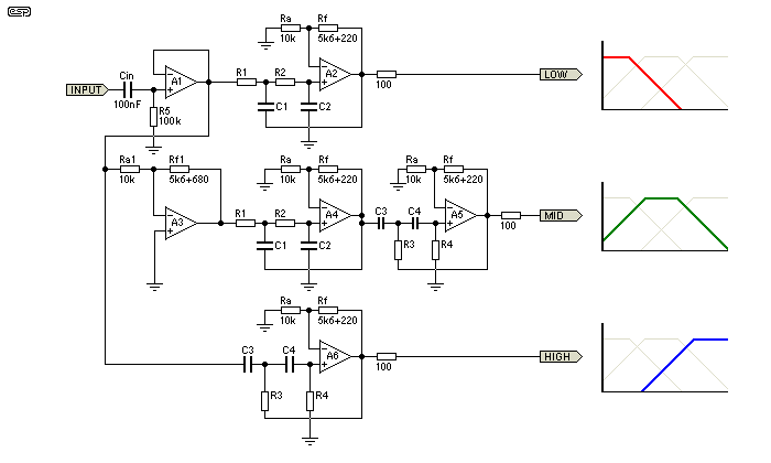
Figure 1 - Crossover Schematic
In the above schematic are shown the low-mid range, mid range mid-high range filters. The x'over frequencies chosen are 300Hz and 3000Hz. Thus the low range filter has a cut-off frequency of 300 Hz, the mid range has a lower cut-off at 300 Hz and an upper cut-off at 3000Hz, and the high range has a cut-off frequency of 3000 Hz. Please see references (2) for the x'over frequencies. The calculations for the x'over are as follows:
Low-mid range: Low pass filter, fh = 300 Hz.
fh = 1 / (2π × R1 × C1), assuming R1 = R2 & C1 = C2 = 10nF. This yields R1 = R2 = 53K (used 56K).
Mid range: Low pass filter, fh = 3000 Hz, followed by a high pass filter fl = 300 Hz.
Assuming R1 = R2, R3 = R4, C1 = C2 = C3 = C4 = 10nF.
For the low pass, fh = 1 / (2π × R1 × C1), yields R1 = R2 = 5.3K (used 5.6K).
For the high pass, fl = 1 / (2 * PI * R3 * C3), yields R3 = R4 = 53K (used 56K).
Mid-high range: High pass filter, fl = 3000 Hz.
fl = 1 / (2π × R3 × C3), assuming R3 = R4 & C3 = C4 = 10nF. This yields, R3 = R4 = 5.3K (used 5.6K).
Note that the mid-range filter is preceded by an inverting amplifier. This is needed for 2 reasons - Firstly, the gain of the mid-range is (1.582 * 1.582) which must be brought back to the level of the low-mid & mid-high ranges (1.582). Secondly (and more importantly), the 2nd order Butterworth filter has an inherent property of shifting the phase of any signal passing through it depending on the signal's frequency so that at cut-off the signal is 90° out of phase with the input (direction of shift depends on whether the filter is high-pass or low-pass).
Thus at 300 Hz the low-mid range filter has shifted the signal by 90° and the mid range has also done the same (but in an opposite direction). Hence, at 300 Hz, the signals appearing at the low-mid range & mid range outputs are going to be 180° out of phase with each other & will cancel out (electrically or acoustically). The same happens to the mid range & mid-high range filters at 3000 Hz. The inverter, with a gain of -0.63 serves to solve both the problems.
Using a 4th order filter (assuming it to be a cascade of two 2nd order Butterworth types) in place of the ones shown will not have the phase-reversal at x'over problem, but you will still need to bring down the mid range filter's gain (this equates to 2 inverters).
The 0.1µF capacitor (Cin) is used with R5 to obtain a lower 3db frequency of about 15 Hz. With the arrangement shown, the overall magnitude response exhibits peaks at the x'over frequencies when the 3 outputs are combined, either electrically or acoustically. This ordinarily does not pose a problem, since the speaker deficiencies themselves will tend to hide (rather veil) the peaks, but with really good speaker systems, the peaking could become evident.
The op-amps used should preferably have a high slew rate and all resistors must be of 1/4 W, 1% metal film type. For the x'over that I have made, the op-amps used are TL074 quad devices. Any other op-amps of your choice can be substituted in place of these. The 100 Ohm resistors at the filter outputs are required if the x'over is going to be connected to the power stages via connectors or any length of shielded lead.
All inputs & outputs must use fully shielded cables (as short as possible). If the circuit is to be assembled on a general purpose board, then try to keep all component leads and wiring as short as possible to avoid pick up (and playback) of radio signals (mine did, but only on touching certain resistor leads).
That concludes the description of the x'over. I hope that the reader will find the material presented here to be of some help in understanding electronics.
I visited the Linkwitz web-site (http://www.linkwitzlab.com) and found that the 2nd order unity gain (sub) Bessel crossover is indeed a 12db/octave L-R aligned unit. Further to this, I indicate the possibility to convert the current design to an L-R alignment by ...
This modification will create a Linkwitz-Riley aligned crossover, which will be superior to the Butterworth version in almost all cases.
It must be understood that the Butterworth alignment is not ideal for a crossover network, because when the signals are summed (electrically or acoustically) there is a 3dB rise at the crossover frequency. This is corrected by using the Linkwitz-Riley alignment which sums flat. See Project 09 for a full description of a 2 or 3-way crossover that is normally 24dB/octave but can be configured for 12dB/octave.
 Main Index
Projects Index
Main Index
Projects Index