
|
|
| Elliott Sound Products | Project 77 |
As is commonly the case, this supply was born of necessity. There is absolutely nothing special about the circuit, except that as shown, it is quite capable of up to 20 Amps intermittently or 10A continuous. Simply use a bigger transformer, bridge rectifier and more capacitors and output transistors to get more current. The basic circuit should be good for up to 50A or so, but it can obviously be increased further (if you really do need a 500A supply!). There is no reason that the supply cannot be made smaller as well (did I hear someone say "Perish the thought." ?). Using fewer transistors and a smaller transformer it will work from 1A upwards.
This is not a project intended for beginners or powering opamps (or other similar frivolous purposes.  ) It is primarily intended solely for powering (nominally) 12V car audio accessories, but can also be used for other tasks that require a 12V supply.
Regulation is not especially wonderful, but that's by design. It could have been made much better, but at the risk of instability and increased complexity, particularly as the current capability is increased. As it happens, the relatively poor regulation is actually a benefit - the supply is intended for testing car power amplifiers and the like, and even with the heaviest wire, there will always be some voltage drop, and this is mimicked very well by the supply.
As a result, the tests that are carried out using this supply will be much closer to reality than if a supply with perfect regulation were used. It can also be used as a battery charger (with care!), as the no-load voltage is very stable.
 |
This project requires knowledge of mains wiring. If you are unfamiliar with (or justifiably scared of) the household mains supply - DO NOT ATTEMPT
CONSTRUCTION. WARNING - Never use lead-acid batteries indoors unless extremely good ventilation is provided. Do not smoke or allow a naked flame within 10 metres of a charging battery, as highly explosive gases are generated during charging. These batteries contain sulphuric acid, which is highly corrosive and will cause severe burns. Exercise safe working and handling practices at all times. | |
The power supply circuit is shown in Figures 1 and 2. A 7812 positive 3-terminal regulator is used for the main regulation, and this is followed by as many power emitter followers as needed for the current you require. The transistors are not critical. I used 2N3771 devices (50V, 20A, 200W) simply because I had a whole bunch of them in my junk-box. These are pretty much ideal, but I suggest that you use whatever you can get cheaply. If you use TIP35s (as indicated in the schematic), expect to use four transistors for the first 10A, and one transistor for each additional 5A peak (or 4A continuous) output capability to ensure an adequate safety margin. The voltage rating is unimportant, as the main supply will only be about 22V with an 18V transformer and any power transistor can handle that. If you need more than 10A, use the circuit shown in Figure 3.
Figure 1 - Basic 10A Power Supply - Power Section
The LEDs are optional, but recommended. 2.2k series resistors (as shown) will give a LED current of about 10mA. Alternatively, use super-bright LEDs, and increase the resistor values. This will reduce the discharge current if the mains supply fails while battery charging. However, the difference is marginal and using the supply as a permanently-on battery charger is not recommended.
The supply is designed to provide high current, and I used a 300VA toroidal transformer and two bridge rectifiers, one for each winding. The 40,000µF electrolytic is one I had to hand, and provides excellent performance. You can get away with quite a bit less capacitance for the 10A version, but ripple may become a problem if there is insufficient capacitance. The circuit shown has a ripple voltage of about 4V at 20A load, and this is quite acceptable as the regulator IC will remove the vast majority of the ripple. Be aware that the capacitor's ripple current will be very high, so ensure that the caps you use have a rating that's high enough to prevent overheating and failure.
Calculate the approximate capacitance you need from the following formula ...
C = ( I L / Δ V ) × k × 1,000µF
(where I L is load current, ΔV is ripple voltage, k = 7 for 100Hz or 6 for 120Hz ripple frequency)
A full load ripple voltage of up to 5V is acceptable for this application, but feel free to have less. As ripple voltage is reduced, the dissipation of the output transistors will increase. This apparently strange behaviour is because the average voltage across the transistors is greater with lower ripple. Unfortunately, there's no straightforward calculation to determine the capacitor's ripple current.
A quick and dirty calculation is simply to multiply the output current by 1.5, so if you are drawing 10A in the load the capacitor ripple current will be around 15A. This applies only to a transformer driven rectifier and filter, operating from 50 or 60Hz mains. There are many dependencies though, in particular the total equivalent secondary winding resistance of the transformer. Bigger transformers have lower resistance and cause higher ripple current - it's not possible to cover this in great detail due to the many variables.
Because the highest rated bridge rectifiers commonly available are 35A, use multiple transformers (and/or windings) and bridges for more current. This will be a lot cheaper than trying to get 100A (or more) devices, and overall performance will probably be better as well. Likewise, use multiple filter capacitors rather than a single large unit - again, these are cheaper, and will outperform a single very large capacitor. Figure 1 shows the recommended method of connecting the multiple windings for higher current, which may be duplicated as many times as needed.
Figure 2 - Basic 10A Power Supply - Regulator Section
As you can see, the regulator is made adjustable over a small range, and will typically give from 11V to 13.8V at full load. With the no-load voltage set to 13.8V (nominal 12V battery voltage), the output will fall to 13.5V at about 1.5A, and 12.8V at around 13A. This is fairly typical of the voltage drops that can be expected in a car installation. Needless to say, if the supply is designed for more current, then the regulation will remain about the same, but at the higher design currents. C4, C5 and C7 should be installed as close to the regulator IC as possible to prevent oscillation.
The components for the current meter are optional, and are only needed if you include the meter circuit. If you don't need the meter these parts (R8-11, VR2, M1) can be omitted. Personally, I recommend that the meter be used so you know just how much current is drawn. Note that the emitter resistors are shown as 5W wirewound, but you can also use 2W or 3W wirewound types if you can get them cheaply.
The output transistors are wired in parallel, with 0.1 ohm 5W wirewound resistors in the emitter of each. The more transistors you use, the better the regulation and peak current capability. The resistors used to drive the optional (but highly recommended) ammeter need only be 1/4W types. These average the individual emitter resistor voltages, and the result will be much more accurate than driving the meter from only one emitter resistor. Although TIP35 transistors are shown, 2N3055 (TO-3) devices can be used. I recommend that plastic power transistors should be clamped to the heatsink - the single screw mounting is inadequate for good thermal performance. The TIP35 has a higher power rating than a 2N3055 (125W vs. 115W respectively).
The diode (D1) from output back to input and D2 (regulator out to +VE) must be high current types - I suggest a minimum of 2A diodes (or two 1A diodes in parallel as I used in my unit). This is used to ensure that the IC is not damaged if the supply is connected to a battery or other voltage source without mains power. R1 and R2, the 4.7 ohm 5W resistors feeding the regulator, provide the only electronic protection available - when the IC current exceeds 1A, the IC input voltage will be reduced and the output voltage will fall. If you use a high current (TO3 style) regulator, then the value of the resistors must be reduced, but the diode will need to have a higher rating to compensate for the increased current back into the main filter cap.
D2 is used to prevent the output transistors from being reverse biased to a degree that they might be damaged. It's not absolutely essential, but does no harm. If the mains fails and the supply is used (and permanently connected to) a car battery or similar, the battery will be discharged by the quiescent current of the regulator and R12. The current will be about 50mA, and if left long enough the battery will be damaged if it discharges to a low enough voltage. This circuit is not intended to be a permanently connected battery charger, and should not be used as such. If you need more than 10A, I suggest the circuit below be used.
Figure 3 - Alternate >10A Power Supply - Regulator Section
The additional transistor boosts the output current from the regulator and provides more base current for the output transistors. This introduces an extra base-emitter diode voltage drop so the output voltage will be a little lower with the driver transistor. R3 is reduced in value to compensate. With the driver transistor as shown, the circuit should be able to deliver at least 100A with 20 output devices. If you need more, duplicate the driver and output transistors, using one driver for every group of 20 output transistors (5A each).
 |
Be warned! There is no diode to protect the unit from reverse polarity if connected to a battery. A series diode would reduce regulation and
be very expensive, and a parallel diode would short the battery (a typical 12V car battery can supply several hundred amps with ease!). This is very
bad for the battery, and not too good for the diode, either (it will probably explode - and yes, I'm serious). An output fuse can be used if desired, but it
will not protect against reverse polarity. Add the circuit shown in Figure 5A to your equipment if you need reverse polarity protection.
In addition, the supply is perfectly capable of melting flimsy test leads, or the ground lead on an oscilloscope (for example). Like all high current power supplies, take great care when building and using this supply, to avoid the risk of severe burns or damaged equipment. |
Protection is with a fuse only, as the supply is sufficiently rugged to withstand almost any abuse for a short period. The minimal protection provided by R1 and R2 is sufficient to allow the fuse to blow before any damage is done to the transistors. I briefly considered an 'electronic circuit breaker', but decided against it very quickly since I needed the supply in a hurry!
The unit I made used a case I had lying around, and although the heatsinking is not substantial, it is adequate for my needs. Supplies intended for testing audio products will need less heatsink than you might imagine, since even high power car amps will not draw full power all the time. However, if you need continuous output current at the maximum for your supply (based on the number of output transistors, transformer size, etc.) then the supply will need more heatsinking than you think. If you do decide to make a 50A version (or more), I suggest that you will need quite a large amount of heatsink - this will not be a real problem (other than financially), since there will be plenty of room - the power transformer(s) will need to be a minimum of 1,200VA (50A output) so the case will have to be quite big. This will leave you with lots of space to play with.
It is important to point out that the heatsinks shown on my unit are suitable for very brief bursts of high current, but are woefully inadequate for continuous duty. For a power supply delivering (say) 20A, the total transistor dissipation will be in the vicinity of 240W or so, depending on the regulation of the power transformer.
To get rid of that much heat requires a substantial heatsink - overall, you will be looking at something in the vicinity of 0.1°C/ Watt, assuming a 25°C temperature rise for the transistor cases - the junction temperature will be higher! Since this represents an almost impossibly large heatsink, you will need a fan - perhaps two or three fans. It is critically important that the fans blow air straight onto the heatsinks.
Many people assume that fans that suck work just as well, but they don't - in fact, they suck. To get maximum heat transfer, you need high turbulence at the surface of the heatsink, and that can only be achieved by blowing air directly onto the fins. Not across the fins - directly onto them.
For those who want to know more about heatsinks, minimising thermal resistance, and ensuring that the output devices stay at a safe operating temperature, see Heatsinks.
Construction is not critical in the normal sense. The regulator IC must be on a heatsink, and needs the capacitors (as shown in Figure 1) mounted as close as possible to the IC to prevent oscillation. No PCB is available for this project, and it is not necessary, since the wiring all needs to be capable of very high currents that would just melt the tracks off a circuit board. The small signal section (regulator, transistor and bypass caps, etc.) can be mounted on a tiny piece of Veroboard or similar.
Use the heaviest wire you can for all main power connections, especially for the output. Any additional resistance you introduce with your wiring will reduce the regulation. I suggest that you keep the leads to the 0.1 ohm emitter resistors short, and most of the power wiring will be pretty much self supporting because of the wire thickness.
Wire the current meter with the return point located as closely to the mid point of the emitter resistors as possible. The accuracy will never be great, but it will be reduced further if there is a lot of copper in the circuit, because the temperature coefficient of resistance for copper is quite high. The 100 ohm output (current monitoring) resistors will not introduce any error. I calibrated my meter to 10A full scale, but calibration to 20A is quite OK, to allow for the peak current capability of the supply.
VR2 (any value from 500 ohms to 2k can be used) is used to calibrate the meter. Use an ammeter and a suitable load, and adjust the pot to obtain the same reading as the external meter. Make sure that the external meter is capable of handling the current you intend to calibrate to. The meter scale can be re-marked as 0-10A or 0-20A, and calibrated accordingly.
If you do not have access to an ammeter capable of at least 10A, then calibration of the meter will require a known accurate low value resistance, and an accurate voltmeter. You can calculate the current by knowing the resistor value and the voltage, and adjust the trimpot until you get the same reading as you calculate. The meter movement is not critical either - use any meter of 100uA to 1mA with the circuit as shown. You will need to adjust the feed resistor values for other movements.
I = V / R Where I is current, V is measured voltage and R is the test resistor value (in ohms)
Typically, you will need a resistor of about 1 or 2 ohms to calibrate the unit. Power will be extremely high - a 1.25 ohm resistor with 12.5V and 10A will dissipate 125W. Eight 10W 10 ohm resistors in a bucket of water will work very well, and will allow you to 'soak test' the unit at full power to make sure that everything manages to stay together. Note that when immersed in water and with DC, you will cause the resistor leads to corrode at their positive ends unless you use distilled water.
The voltage control may be calibrated, or just place a marker on the panel for 13.8V. If desired, a voltmeter can also be included in the circuit - if used, this should be wired across the output terminals.
The author's unit is shown in Figures 4 and 5, based on the schematics in Figures 1 and 2. It was designed as a 10A supply. As I mentioned, the case is one I had lying around, and I can't use mine at its peak of 20A for extended periods as there is nowhere near enough heatsinking. However, it serves the purpose that I needed it for, which was to test some car amplifiers I had (also lying around). I have found it to be extremely satisfactory, and since it can be completed in an afternoon, this makes it a simple project that should give many years of service.
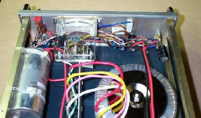
Figure 4 - Prototype Supply (Front Panel Inside View) - 10A Version
The meter was already in the case I used, the toroidal transformer is clearly visible, as well as the filter capacitor. The bridge rectifiers are on the vertical aluminium bracket between transformer and filter cap. The control electronics (regulator, transistor and small caps) are on the piece of Veroboard just to the right of the meter. The cap on the extreme right is the output capacitor. The regulator is thermally connected to the front panel to provide heatsinking (don't forget the insulation washer and bushes!).
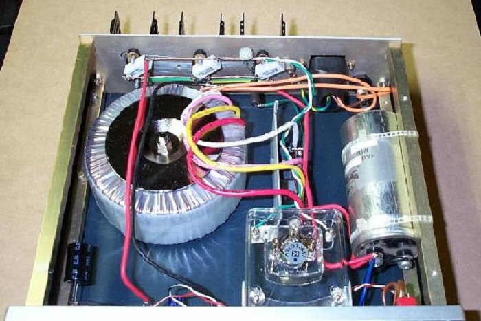
Figure 5 - Prototype Supply (Rear Panel Inside View) - 10A Version
In the above view, the power transistor mounting, emitter resistor and mains input can be seen. The small round thing in the top-centre of the photo is the meter setting trimpot. All mains connections should be protected against contact. This includes the IEC socket and mains fuse.
From this angle you can see that the filter cap is an old computer grade unit (salvaged from my trusty junk box), and you can also see that I only used three power transistors. As I mentioned before, I used 2N3771 devices, and these are much more powerful than the 2N3055s I suggested, but are probably very hard to get (and almost certainly expensive). The little heatsinks I used are just visible at the back. The mating surfaces were carefully machined so they were completely flat, and are thermally bonded to the aluminium backplate with heatsink compound and lots of pressure from the transistor mounting.
There is no doubt that a unit such as this may be used for powering car amplifiers and possibly other gear as well, and most have limited or no protection against reverse polarity. If the supply is likely to be disconnected and re-connected with any degree of regularity, there is a real chance that at some stage, it will be connected with reverse polarity. Note that the two circuits below are separate, but they can be used together. These circuits are not part of the power supply - they are used as part of the equipment being powered.
Figure 6 - (A) Reverse Polarity & (B) Over-Voltage Protection
The polarity detector uses a relay (rated for at least the maximum equipment current. Should the supply be connected the wrong way, the relay cannot close. The 'Reverse' LED will come on, and the equipment is saved from the embarrassment of allowing its magic smoke to escape. A proper connection will cause the 'Correct' LED to light, the relay will close, and power is made available to the circuitry. The relay coil should be rated for the equipment voltage (typically 12V for this application).
Because no equipment can ever be 100% failure-proof, expensive equipment may also benefit from over-voltage protection. Should the output of the supply exceed about 16V (with the values as shown), the SCR will conduct, short-circuiting the supply - commonly referred to as a crowbar circuit. This will cause the fuse to blow before the equipment is damaged (a fault in any power supply can cause the voltage to rise to the full unregulated value). The SCR needs to be able to conduct a non-repetitive peak current that is at least 5 times the fuse rating ... preferably higher. The C122 is rated for 8A continuous, but will handle over 80A for 10ms. The 'F' refers to the voltage rating (F means 50V), but any voltage is fine. The preferred device is the BT152-400R, which can handle 200A for 10ms. It may be possible to obtain an even bigger device, but the options shown are a good starting point. R3 is optional, and protect the SCR from excessive peak current. With the value shown (0.22 ohm), the maximum possible current is about 60 amps.
The circuits shown in Figure 5 belong in the equipment being powered ... not the power supply. The same circuit should be added to each piece of gear you expect to connect to the supply. Note that car equipment (amplifiers, CD players, etc.) are designed to be able to cope with high transient voltages, which can be up to 40V for a nominal 12V system. Do not include the over-voltage protection in any such equipment that is likely to be connected to a car's supply, as the circuit is guaranteed to trigger at some point. The crowbar circuit may be wired into the power supply output circuit if you prefer. Make absolutely certain that the supply variable control cannot allow the output to exceed the crowbar trigger voltage!
More complex crowbar circuits can be used that include a time delay to reject transient pulses, but these are outside the scope of this article.
Since many readers may want higher power than the unit shown, here are some guidelines for bigger units.
- Don't expect to build a 100A version (or more) in one afternoon.
- Use one 2N3055 for each 5A of peak output current (4A continuous) - Each transistor will dissipate about 40W. There is no reason that you can't use more though, and this will improve heat transfer from junction to heatsink.
- Assuming a current gain of 20 for the 2N3055s (fairly typical), one 5A TO-3 regulator will drive up to 100A (use 25 transistors)
- For more current, use a boost circuit around the regulator IC (up to 500A output, with 100 transistors!). I shall leave details of the boost circuit to you (it is very commonly used, and many examples exist on the Net). Alternatively, use the circuit shown in Figure 3
- Consider using higher power transistors to reduce component count. The cost will probably be higher though, and heatsink performance will not be as good due to higher thermal resistance between junction and heatsink.
- Use multiple transformers and bridge rectifiers, rather than a single really big one of each
- The transformer(s) need to be rated at 300VA for each 10A continuous. 100A requires 3kVA
- Transformers can be overloaded by up to 200% for short periods (50% of the time on load, and 50% off). Other overload ratios can be calculated (but excess or continuous overload is not recommended!). Consider fan cooling the transformer(s)
- See the article on Power Supply Design to learn about capacitor ripple current (this will be extreme!)
- See the article on Heatsinks to learn more about the best way to mount the transistors.
- If you need a lot of current, consider using a switchmode supply instead (see below)
The above is not extensive, but you get the idea. For most applications, the unit shown will be sufficient. I doubt that too many constructors will want to build 500A supplies, but if you do have a need for such a monster, then this circuit should do the job quite well. Hmmm ... 500A at 13.8V is 6.9kW - I'm almost tempted to build one for the hell of it (just kidding. )
Even a 1kA (1,000 amps) unit is not impossible with a few minor modifications (including the regulator boost circuit), but for anything over the basic 10A unit shown, some extra heavy duty connectors and fuses will be a good idea. I am doubtful that this will be needed for most normal applications. It's worth noting that most power outlets and household mains wiring is rated for a maximum of around 2,400 Watts, so a dedicated circuit will be needed to handle the current.
For what it's worth, if you do need much beyond the basic 10A supply, use the supply as shown connected to a car battery. It can safely be left connected permanently if the supply is set to 13.8V (check the temperature though - lead acid batteries have a temperature dependent 'float charge' voltage). The unit is then a battery charger, but will not introduce any hum onto the battery output voltage (unlike conventional chargers, which are not smoothed). Be aware that if the mains fails, the battery will discharge at about 50mA because there is no simple way to prevent discharge.
Alternatively, you can get 12V switchmode supplies quite cheaply, and as long as they have a voltage calibration they can be paralleled by using 0.1 ohm resistors from the output of each supply to a common output rail. Each supply should be adjusted so that the output voltages are within 0.1V or better. This ensures that they will share the current equally. Some are designed to allow parallel connections without needing external resistors. A 200W 12V supply is good for over 16A, so it's easy to get a very powerful supply by using 2 or 3 of them.
 Main Index
Projects Index
Main Index
Projects Index