
|
|
| Elliott Sound Products | Project 44 |
 |
Please Note: PCBs are available for this project (using the latest version of P05). Click the image for details. |
Having just built your new masterpiece, it is usually with great trepidation that one applies power. There are few things quite so disheartening as seeing your creation 'go up in smoke' just because of a simple wiring mistake.
The easiest way to avoid this is to have a power supply that allows you to adjust the voltage, so you can see that everything works as it should before the main supply is connected. The lab supply shown will current limit at around 800mA (this varies a bit because of the regulators), and can supply from ±1.2V up to about ±25V.
Using a dual-gang pot allows both supplies to be set simultaneously to the same voltage (close enough - there's rarely a need for absolutely accurate voltages for most circuits), and you can add metering for voltage and current if you want to. These will add substantially to the cost, but can be very useful. An ammeter for each supply is highly recommended, as that lets you see immediately if the current is higher than expected.
| This project requires knowledge of mains wiring. If you are unfamiliar with (or justifiably scared of) the household mains supply - DO NOT ATTEMPT CONSTRUCTION. |
The power supply is based on the LM317 and LM337 variable 3-terminal regulators ICs. While it is no powerhouse, it is quite satisfactory for testing all preamps, many other projects, and even most power amps, as long as there is no speaker connected.
Figure 1 shows the complete circuit diagram, and it is quite simple. There are only a few things that you need to be careful with (apart from the mains wiring), and these are ...
NOTE: Some searching revealed that SGS Thompson (ST) ICs may be different from National Semiconductor devices, so caution is advised. The IC will not be damaged if Pins 2 & 3 are reversed (because of the diode), but the regulator won't work. The pinouts above are from the National Semiconductor datasheet. If you use the P05 PCB for this project, then you must make sure that your regulators use the standard National Semiconductor pinouts.
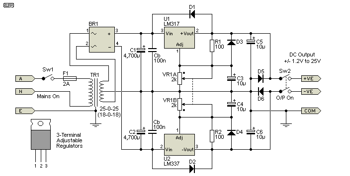
Figure 1 - The Complete Power Supply Circuit
The transformer does not need to be especially large - typically a 60VA unit should be sufficient, although a larger one will do no harm. Likewise, the 4,700µF caps will be quite large enough for the intended purpose, but can be increased if it make you feel better. If you use the P05 board, it uses 2 × 2,200µF caps mounted on the PCB. Anything larger will be off-board as they won't fit in the space allowed. More than 10,000µF will not give any advantage though. The bridge rectifier should be rated at about 5A for continuous operation.
The two capacitors marked 'Cb' are 100nF/ 50V 'monolithic' ceramic bypass caps for the regulator ICs. They will be needed unless the regulators are very close to the filter caps (C1 and C2). Along similar lines, it's important that C5 and C6 are also as close as possible to the regulator outputs. The same applies to C3 and C4, which need to be close to the regulator Adjust pins. You can add bypass caps to the regulator outputs as well - if you use the P05 circuit board these are already provided for.
The 2k dual-gang pot (the dot indicates the fully clockwise position) need only be a standard quality unit, but MUST be linear - do not use a log pot. The ideal is a dual wirewound unit if you can get one, as this will be more robust and will have better tracking. A standard carbon pot is actually running at slightly above its ratings at maximum voltage, but this is unlikely to cause a problem.
Make sure that all mains connections are shrouded with heatshrink tubing to prevent accidental contact. The entire power supply chassis should be earthed, and make sure that all mains and earth wiring complies with the regulations where you live. I recommend that the output GND terminal is not connected to the mains earth. The output of lab power supplies should always be floating.
Output connectors should be combination binding-post/ banana socket types, and additional connectors can be used if desired. Make sure that any connectors used cannot short circuit as the plug is inserted - although the ICs have protection, it is better not to have to rely on it.
In use, always make sure that the voltage is set to minimum before connecting your test circuit. Advance the voltage slowly, watch for abnormal current and feel for anything that may be overheating.
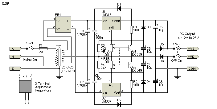
Figure 2 - The Complete Power Supply Circuit, Version 2
Can't find 2k pots? It seems to be that 2k pots can be very difficult to obtain, and likewise 2.5k pots which would be a suitable alternative. They may be obtainable as single gang, but dual gang can pose a real challenge. Figure 2 shows how you can use higher value pots, with the addition of a transistor and resistor. These can be wired directly across the pot terminals, and although BC5x9 types are shown, any small signal NPN and PNP transistors can be used. The pot can be up to 50k with no ill effects using this scheme. One minor disadvantage is that the minimum voltage is slightly higher (by 0.65 - 0.7V), but this is not normally a problem.
The addition of voltage and current meters is useful, but is fairly expensive at about AU$20.00 each (and it can be a nuisance finding 1A current meters). If you want to add meters, Figure 2 shows how they should be connected. Only a single voltmeter is shown, and it will be necessary to check the internal resistance to determine the value of the calibration resistor. Although this meter is connected between +ve and -ve supplies, it is calibrated to show the average value of one supply voltage only (since this is a tracking supply, they will be very similar in voltage).
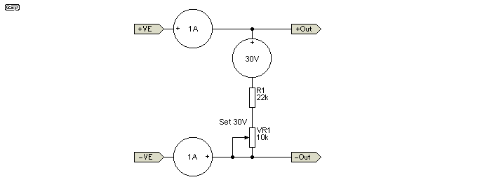
Figure 3 - Addition of Meters
I suggest that a trimpot be used so you can calibrate the voltmeter (assuming that a 30V meter can be obtained), since it is unlikely that the right resistance will be available. Figure 2 assumes that the meter has a resistance of about 30k - if yours is substantially different you will need to adjust the values. A pair of ammeters is highly recommended. With these, you can see instantly if the current rises faster than it should, which means there is a fault in the circuit being tested. A variable power supply without current metering is not helpful!
If you have to use a 1mA meter, then the scale will need to be redrawn, and the series resistor calculated.
For all calculations, I will assume a meter with 1mA full scale deflection (FSD), with a coil resistance of 58 Ohms. This is typical of one found in an Australian electronics supplier catalogue. Figure 3 shows the way to connect a series resistance to make a voltmeter, and parallel resistance to create an ammeter.
Calculating the value of the series resistance is easy. We want a full scale reading of 30V, but since the meter is across both supplies, the actual voltage will be double this, or 60V. For more details for meter calculations and setup, see the article Meters, Multipliers & Shunts.
R = (V / I) - Rmtr where R is the series resistance, I is FSD current for the meter, and Rmtr is the meter's resistance.
R = (60 / 0.001) - 58
R = 60k (The 58 Ohms can be ignored as insignificant
Figure 3 shows the series connection for a voltmeter, using a trimpot to allow calibration.
If you cannot obtain 1A current meters, you will need to use a 1mA (or some other value) meter, and make a shunt so it will measure higher current. The shunt resistor will normally be a very low resistance, and must be rated for at least 1 Amp. To calculate the value of a shunt resistor, you will need to do the following ...
There is a small error here because the meter is in parallel with the shunt, but the error is negligible for this current (0.1%). Figure 3b shows the normal connection for a shunt, and Figure 3c shows the way you can cheat, using a fixed resistor and a trimpot for calibration. As shown, this will result in a voltage drop of 0.1V at 1A, which is unlikely to cause a problem. A 5W wirewound resistor should be used as the shunt resistor.
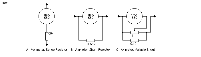
Figure 4 - Series and Shunt Resistors
Because the shunt resistance is so low, it will be difficult to make, and even harder to measure. It is usually easier to use a fixed resistor (e.g. 0.1 Ohm) with a trimpot to set the meter. This can be calibrated after the power supply is complete - connect a 10 Ohm 10W resistor between the +ve and -ve supplies, with a multimeter (set to the amps range) in series. Adjust the voltage until the multimeter shows 0.5A, then adjust both trimpots so the two meters read exactly 1/2 scale.
 |
All DC meters are polarised, so the terminal marked + must go to the positive side of the supply as shown in Figure 3. Although reverse polarity will not damage the meters, the readings will not be as useful as they should be. (I.e. the needle will be hard against the stop, trying to display a negative voltage  ) ) |
Your power supply is now ready for serious use. The maximum current of 800mA to 1.5A (depending on the regulator ICs) will be enough to test any Class-AB amp up to +/-25V (most will work fine at this voltage). Note that it will not be suitable for a Class-A amplifier, since these draw far more current that this supply is designed for. All preamps can be tested, but make sure that you do not exceed the supply voltage recommended - this will be typically +/-15V for opamps.
 Main Index
Projects Index
Main Index
Projects Index