
|
|
| Elliott Sound Products | Project 244 |
 Main Index
Projects Index Main Index
Projects Index
|
The LM3915 has been a mainstay for LED 'VU' meters for a long time, and is used in Project 60. The IC is now discontinued, and isn't available from any reputable suppliers. I expect that the reason is that it used old fabrication techniques, and was difficult to migrate to modern IC manufacturing methods. Regardless of the reason, they are no longer made, and while you can get (allegedly) genuine ones from the usual suspects, there's a significant risk that the ICs you get may be anything.
The Samsung KA2284 is a single in-line package (SIP) that can drive 5 LEDs. They seem to be readily available, but not from any of the major suppliers. These work in much the same way as the LM3915, and use a single supply.
A lot of equipment now just uses a 3-LED system, with one showing that signal is present, another showing that you're approaching the peak, with the final LED indicating overload. As near as I can see, there are no ICs designed for this, so the entire circuit has to be made with discrete components (other than opamps or comparators). It's no-doubt possible to use a PIC or similar, but this isn't something I've investigated.
The 3-LED system is far less distracting than a 10-LED bargraph, as it won't be constantly flickering with the level. There's (probably) a better chance that you'll see overloads as well, since there are only three LEDs, rather than the 10 provided by the LM3915.
One real advantage is that you can set the thresholds to any voltage interval you like. As shown, signal is shown as 'present' when it's at -30dB (referred to the peak level, nominally 1V). This gives an RMS voltage of 707mV, but it can be adjusted over a wide range. The first stage is a rectifier, and a full-wave type is always preferred because it will 'catch' peaks of either polarity. Unfortunately, this presents a problem that would require another opamp to solve.
The rectifier shown is an oddity, because it makes use of the ability of an LM358 opamp to function down to zero volts input. This comes at a cost though, as the output is high-impedance, and ideally it requires a buffer to drive the peak hold capacitor. The arrangement shown is described in detail in the app. note AN001 (Fig. 8). Without the buffer, it's a half-wave rectifier when driving a load (such as the 'peak-hold' capacitor).
Unfortunately, the input impedance is nonlinear and the input must have a low impedance or the circuit may introduce some distortion to the audio signal. It really needs a front-end amplifier, but that becomes a nuisance, and isn't included. An interesting (but generally not publicised) point is that any single supply circuit referenced to ground must have a non-linear input impedance if the input can swing both positive and negative. It rarely causes problems unless the source impedance is high. If in doubt, use a buffer or gain stage to isolate the source from the metering circuit.
The LM3915 got around the limitations of a single-supply circuit by using half-wave rectification. I've never liked the idea, but 10s of thousands of mixing desks have been made using LM3915s, and I've not heard anyone complain. Due to the arrangement used in this design, the rectifier is (theoretically) full-wave, but the capacitor (C1) means that it's predominantly half-wave.
The circuit works out rather well, and 2 × LM358 dual opamps is sufficient for one channel. The circuit is shown as a single channel because you'd generally use a pair of these circuits side-by-side for stereo. The LM358 opamps are cheap, and draw very little power. No attempt has been made to use the LEDs in series (to minimise the current drawn), because there are only three.
A useful circuit will always allow you to set levels to what you require, and that's certainly true of the design shown. While it may seem somewhat 'clumsy' with four opamps, it is also a good learning exercise, as you can see how every part of the circuit functions with a scope.
If you use a dedicated IC, everything that happens is hidden from view, and there's no opportunity to learn anything from it. If (when) you can no longer get the IC, there is no way to repair a failed unit, so it becomes scrap. The LM358 is also available as the LM2904, which is almost identical, but has a lower maximum supply voltage (26V or ±13V) vs. 30V for the LM358.
The circuit diagram shows that the circuit isn't complex, but unfortunately the resistors do take up a fair bit of space. However, the circuit can be assembled on Veroboard and it's not large - my prototype measures 27mm × 50mm (excluding LEDs). The two 10uF and 1μF caps are best laid flat so two boards can be mounted side-by-side with a gap of less than 10mm between them. The trimpot is not essential, and it can be replaced with a 7.5k resistor for 1V RMS detection (~1.37V peak with a 12V supply). C2 is optional, and the variation of the Vref bus is only a few μV without it.
The operation of the comparators (actually opamps used as comparators) is straightforward. Provided the rectified signal voltage is below the reference for each comparator, the output is low. My 'second rule of opamps' states that without feedback, the output assumes the polarity of the most positive input. Thus, if the -Ve input is more positive that the +Ve input, the output will be negative (or [close to] zero volts in this case). The converse is also true, so when the signal exceeds any of the thresholds, the corresponding output will go to the supply (less ~1.5V), turning on the LED via its current limiting resistor.
I don't recommend that you use the preamp supply - a separate regulated 12V supply is preferred. This can use the same rectifier and filter caps as the preamp supply if the transformer can handle the extra current (about 25mA worst case). Depending on the LEDs you use you may need to adjust the value of the limiting resistors (R8, 9, 10). If you use high-brightness types it should be possible to reduce the current to 1-2mA, perhaps less. Be careful with grounding - you don't want the LED current in your preamp's ground circuit, as it will create lots of noise as the LEDs turn on and off.
In theory, with two boards, the second one doesn't require the reference voltage or the voltage divider (R5, 6, 7), but that would mean they can't be tested individually. For the small cost, it's not worth trying to save a few resistors and a pot. As shown, the averaging cap (C1) is only 2.2μF, so the hold-up time is fairly short. If you'd prefer a longer hold-up (LEDs stay on for longer), feel free to increase the value. I tested a number of values, and there's a surprisingly big change to the 'look' of the display when different values are used. It's unlikely that you'd go much higher than 4.7μF - I tried 10μF, and it was just too slow. You might prefer that, so it's worth a try. Likewise, it was just a bit too fast with a 1μF cap.
The system is peak-reading, so it responds to the highest peak encountered. The LED on-time depends on the amplitude and duration of a peak. In use, we expect to see the green LED 'on' most of the time, with the orange LED flicking occasionally. When set up to monitor the absolute level, the red LED should remain off, apart from a very rare transient. Testing with music and speech from an FM radio shows just how well-controlled the FM broadcast levels are.
The idea is to set it up so it shows you want you want to see. It's just as suitable for monitoring the output of a power amp as for keeping recording levels in check. If used as a power amp clipping indicator you must include a suitable attenuator at the input. For example, if the amp uses ±35V supplies, the peak output voltage would be set for around 30V. Since the input is likely to be calibrated for ~1V RMS (1.4V peak), 30V has to be reduced to 1.4V. You can use a trimpot, or just settle for 18k (from the speaker output) and 1k to ground at the input of the circuit. Anything over ~27V peak will cause the red LED to come on, giving you a bit under 2dB of 'headroom'.
Setup is important. In general, provide as much signal as you can to the input, while making sure it doesn't exceed ±12V. With R4 at the default value of 33k, the nominal maximum input level is 1V peak with VR1 set to its mid-point. You can adjust this to suit your needs, by reducing the value of R4 (a minimum of 2.2k is suggested). If you need greater sensitivity, use an external preamp. No fancy ICs are needed - another LM358 will be fine with supplies up to ±15V.
Some users may prefer that only one LED is on at any time, but this isn't as easy as it may seem at first. The simplest (but pretty crude) is to use small-signal MOSFETs to short out the first two LEDs (-30dB and -6dB) if the next higher LED is on. No other parts are needed - just a pair of 2N7000 MOSFETs. This is a 'brute-force' approach that lacks even the tiniest bit of finesse, but it's probably the easiest way to do it. It can also be done using a simple CMOS logic IC, but that would take up too much space and would be hard to wire up. The pinouts for most logic ICs are not particularly 'Veroboard friendly'.
Because it is a brute force solution, the current required by the circuit will be close to 15mA when the peak LED is on, but that should not be a major concern. The main point is that it can be done, with very little added complexity. Any other solution will need more parts and more complex wiring. The general idea is shown below, showing only the level comparators, limiting resistors, LEDs and MOSFETs.

Q1 and Q2 are used to short out 'G' (green) and 'Y' (yellow) LEDs if the next higher LED is on. So, 'G' would normally be on, but if 'Y' is turned on, Q1 is also turned on, and 'G' is shorted (and therefore turned off). The rest of the circuit is unchanged. The 'sophisticated' way to have only one LED on at a time requires a current source that will use more parts and require more board space than the two MOSFETs. For a project that's meant to be easy (and cheap) to build, adding greater complexity isn't a viable option.
Of course, if it were done with all SMD parts it would be a great deal smaller, but a great deal harder for hobbyists to build. Anyone who has used them will know how difficult it can be. Not so much the soldering - that's easy enough with a fine-tipped soldering iron and a steady hand, but getting (and keeping track of) the tiny parts is a real challenge. Should you happen to drop the last 10k resistor you have in your collection (or it flies out of the tweezers used to pick it up), then everything stops until you can get some more.
Regular readers will be well aware that I use SMD parts only if there is no alternative. Naturally enough, if you are used to SMD and have everything you need (including a PCB) then by all means do so. You can't use Veroboard though, as the track spacings are too large and don't align with ICs. You'll have to design a PCB if you wanted to use SMD parts - there's no real alternative that I know of. There are some adapters and an Arduino 'shield' you might be able to use, but the latter is more likely to be intended for digital circuits than analogue.
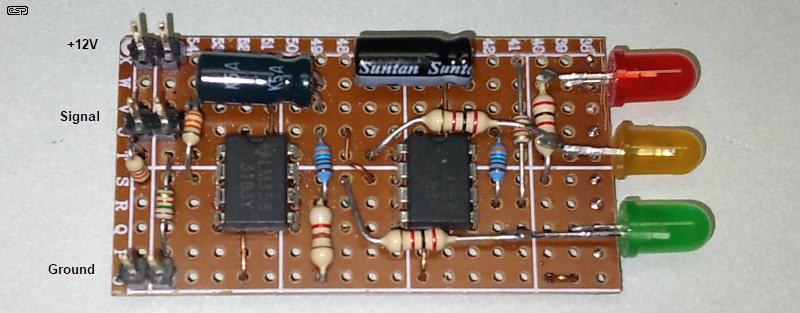
My prototype is shown above, built on Veroboard (as are most of my prototypes). If you look closely you'll see that many of the resistor values are different from those shown in Fig. 1. This only changes the thresholds, not the way the circuit works. Overall, the end result is not bad - it does what I designed it for, and doesn't do anything unexpected.
I didn't include C2, and a few initial tests were performed without the bypass cap! The LM358 is one of the few opamps that can tolerate a supply with long leads (about 1M in my case) without oscillating wildly. That doesn't mean you can leave it out though, as it also helps to suppress switching noise. The LM358 helps here too, as it's quite slow. The slew rate is a rather leisurely 0.5V/μs.
Like many ESP projects, this is intended to provide you with a starting point, and lets you analyse the circuit's behaviour. It lends itself to as much experimentation as you like, with the only restriction being that you must use the LM358 or LM2904, because most opamps can't operate with their inputs at zero volts. The power supply needs to be fairly stable, because it's used to derive the reference voltage. A precision voltage reference could have been used, but that just adds cost to a project that's intended to be cheap to build.
This is a 'utility' design, and it can be adapted/ modified for a variety of applications. Note that the rectifier (U1A) rectifies negative input voltages. This isn't readily apparent from the circuit. If you need to monitor a positive voltage only, omit the rectifier and use a voltage divider or a pot to set the input level to the comparators. If you were to use the circuit to monitor a battery voltage (for example), you may wish to change the LED colours around.
The circuit will also function down to about 7V, but the LED current limit resistors have to be reduced. You don't have much headroom, as the opamps can only get to within 1.5V of the positive supply.
There are no references, as the circuit is derived from basic principles. Every technique (other than using the MOSFETs to short out the LEDs) is described elsewhere on the ESP site.
I do recommend that you read the datasheet for the LM359/ LM2904 opamps, available on-line from multiple sources.
| Main Index
Projects Index
|