
|
| Elliott Sound Products | Project 242 |
 Main Index Main Index
 Projects Index Projects Index
|
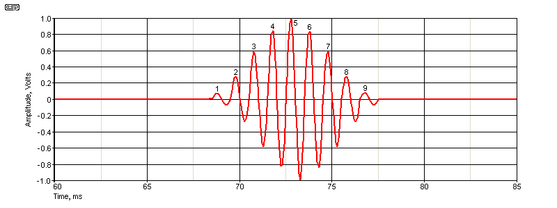
The Project 58 'Linkwitz Cosine Burst Generator' was published in 2000, and a new version was designed by Ray Hernan in 2008. While the 2008 design doesn't use any unobtainable ICs, it's also fairly complex (far more so than the original). The original used eight ICs, the updated version uses nine, and this only uses six. The design is intended to achieve the same results as the original, but it's approached differently. It may not be quite a 'elegant' as the previous version(s), but it's simpler, and therefore easier to build. Unlike the original that used 10 half cycles, this version uses 9 full cycles. This changes the waveform and affects the harmonics.
With any test equipment, we want something that (ideally) uses no esoteric parts, with commonly available ICs used throughout. I have no idea if this new version will gather many fans amongst the DIY fraternity, but it's fairly simple, using only six ICs in all. There's a resistor/ diode matrix that's used to decode the outputs from a 4017 CMOS shift register, completely eliminating all difficult ICs from the circuit.
The benefit of the cosine burst is that it generates the minimum amount of infrasound and harmonics, which are both very pronounced with a 'traditional' tone-burst ('on-off') generator. While the cosine burst is intended for testing loudspeakers, it may also be a better proposition for amplifier testing as well. This is because it's closer to a real musical transient, without instantaneous start and stop times.
Ideally, the burst is repeated once every second. For speaker response tests, the burst frequency should be stepped in 1/6 octave increments (1.1225 × f), starting at 20 Hz for full frequency coverage. The generator will track the input frequency, so once you have it set up, the frequency can be changed at will. The input level should be around 1V RMS (1.4V peak) to ensure reliable clock pulse generation. The output can be attenuated with a pot if necessary (this isn't shown in the circuit).
Another way to get a 'nice' (actually, almost perfect) tone burst is to use a bandpass filter, tuned to the frequency being applied. This removes the low frequency and high frequency 'artifacts' far more effectively than a cosine burst, but a tracking oscillator/ filter is needed which is a significant effort to create. They can be separate (and separately tuned), but that makes the setup for each frequency much more difficult. The results are excellent, but having to tune the oscillator and the filter will get tiresome very quickly. The filter should be a high-Q type (a Q of around 10 is optimum), and that doesn't make it any less unfriendly to work with.
The idea is simple conceptually, but practically it's hard to get everything right. The tracking oscillator/ filter is a challenging design, not helped at all by the need for accurate (close-tolerance) variable resistances. Most pots are rather 'ordinary' for tracking, and that will affect the amplitude of the signal. The way this would be done is to use a 'normal' tone-burst generator, set for 4-5 cycles of the input waveform. The filter will require more than 5 cycles to reach peak amplitude, so the build-up is slow, as is the decay when the burst signal ends. This approach will give the best results possible, but it won't be considered due to the difficulty of implementing the tracking oscillator and filter.
The circuit isn't particularly complex, though some may disagree. Even though there are only six ICs, there's a lot of inter-wiring, and some of it will be tricky to get right. CMOS ICs don't have the pins where we'd like them to be for the connections required, and the passive parts don't help much either. It would be a fairly easy project with a double-sided PCB, but it's highly unlikely that there will be enough interest to warrant having boards made.
There are some inevitable compromises in this circuit. The 'off' time is slightly variable, depending on the applied input frequency. The goal is for one pulse every second, and while it is close, it's not a fixed value. It's extended at low frequencies, and reduced at high frequencies. There may also be small glitches in the waveform at high frequencies due to the simplified switching system used.

The burst is 9 cycles, with the amplitude increasing up to the 5th cycle, then decreasing over the next four cycles. Any small glitches in the audio waveform will have very little effect on a measurement. I've used resistances to get 'close enough' to each voltage level. Precision (and very odd value) resistors could have been used, but the difference is academic. From a pure maths standpoint, there are certainly amplitude errors, but compared to the overall objective the difference is small.
The 4017 is a 5-stage decoded Johnson counter, which provides a '1' at each output in turn. O0 isn't used, and 09 indicates that the sequence has completed (with its falling edge), and the counter is reset via the pulse generator and timer circuits. The audio is switched with 5 × 4066 bilateral switches. Unfortunately, each IC has four switches, so most of one 4066 IC is unused. Also unused are U2B and U5F, and the unused inputs should be connected as shown.
U5 is a hex Schmitt trigger/ inverter, and while it would have been possible to use fewer of the internal circuits by using inverted logic, it makes more sense the way it is. The two R/C networks are configured as monostables to provide the timing functions. The pulse generator detects when O9 goes low (indicating the end of the sequence), and that recharges the timer capacitor (C3) and turns off the output. Q1 is a BC639 or equivalent, which is needed because of the high pulse current.
After the preset hold-off time has elapsed, the counter is re-enabled and the sequence starts again. The waveform is difficult to synchronise on an oscilloscope, so the 'Sync Out' is provided to apply a positive-going pulse at the start of the burst waveform. The trigger amplitude is from -6V to +6V. The scope's trigger circuit will be set to 'external' so the scope triggers reliably for each burst.
C4 is very important, because the charge current into C3 is high (over 100mA). C4 provides sufficient 'local' storage for the charge current, and it must be as close as possible to the collector of Q1. This prevents the charge current from creating a supply glitch which may disturb the remainder of the circuit. You may increase the value if you wish, and anything over 33μF will work.
The incoming signal is buffered by U1A, and the output is fed to the 4066 analogue switches and to the clock generator (U2A). The comparator generates the clock pulses needed to operate the 4017 counter at the zero-crossing of the sinewave. The outputs switch on the positive-going edge of the clock signal. The comparator has a small hysteresis created by R5 and R6 so it doesn't output random noise with no input signal.
The resistor/ diode network on the counter outputs provides a positive pulse from '1' for the first and last (9th) cycles of the input frequency. '2' gets a pulse for the 2nd and 8th, cycles, '3' for the 3rd and 7th cycles and '4' for the 4th and 6th cycles. O5 provides the 'middle' (5th) pulse, which is at the maximum amplitude. The resistor/ diode matrix works because each output goes from low to high in turn. The pulse is fed to the appropriate 4066 gate either by a diode (with the resistor acting as a 'pull down' so the output isn't floating), or via the resistor, with the diode preventing the voltage from being pulled down by the 4017 output.
You will need to look at the logic states and the wiring to see just how this works. It could have been done using diodes and a resistor 'pull down', but that would add four extra diodes, and the resistors are still needed. The arrangement shown is the most efficient use of parts, but it's not something you'll see used very often. The 22k resistors were used to minimise the load current for any output. CMOS ICs can source or sink up to ~1.5mA with a 12V supply, and 22k keeps it to a maximum of less than 550μA.
The amplitude of each cycle is determined by R15 ... R19, with the value adjusted for each output. The output level is determined by the resistor switched in circuit at any one time, so for the 5th pulse (maximum) the output voltage is the same as the input. A 1V peak input provides an output of 1V peak. This can be altered by increasing the value of R20. 33k means unity gain for the output pulse, and a higher value increases the output level.
Note that all ICs operate with a ±6V supply. Zero volts (ground) is used only for the input stage, comparator and output stage. This should ensure a 'clean' ground, with no switching artifacts. Not shown are bypass caps for each IC, and these must be included to prevent erratic switching. 100nF multilayer ceramic caps are needed across the supply pins of each CMOS IC, and from each supply to ground for U1 and U2.
The output of the burst generator will typically go to a small power amplifier (with a level control pot between the generator and amplifier). The level should be adjusted to be just loud enough to get a clean signal from the measurement microphone, and will typically be no more than 1-2 watts. You'll need more for a subwoofer driver, because they are generally fairly insensitive.

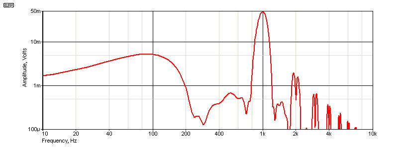
If you wish to modify the output 'envelope' (nominally a cosine burst) you can play with the values of R15-R18. You can create any burst pattern you like, but anything other than the cosine burst is unlikely to be useful. You can use trimpots for R15 ... R18 if you wish - this will let you tweak the burst waveform for minimum harmonic (and sub-harmonic) levels. The spectrum is shown below, and it demonstrates that the low and high frequency energy are fairly well controlled.

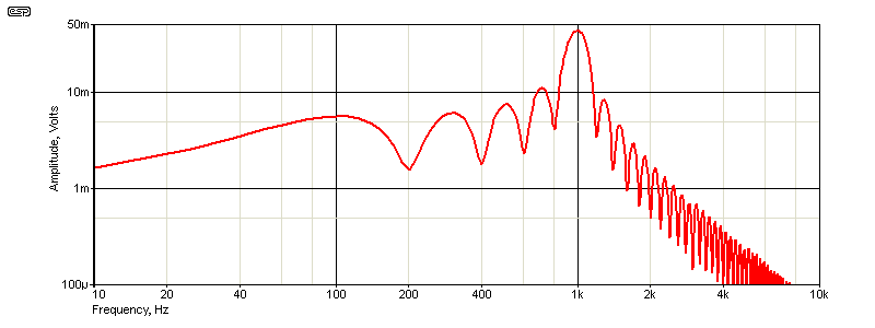
As you can see, a standard tone-burst signal has a fairly broad frequency spectrum. With five cycles there's significant 'out-of-band' energy, both above and below the nominal frequency. This causes a great deal of 'clutter' in a measurement, making it harder to see the true transient response. By way of comparison, the cosine burst is far less cluttered, and the burst spectrum is a lot cleaner.

The amplitude at 500Hz is over 36dB down for a cosine burst, vs. only 15.5dB for a standard tone-burst. There's also a peak in the standard burst at 710Hz that's only -2.5dB below the maximum, but that's not present with the cosine burst. Overall, the low frequency energy is below -37dB down to 200Hz (1kHz input). The response above the burst frequency is also much cleaner, with most of the upper frequencies removed. Most of the 'artifacts' are not harmonics of the 1kHz tone. The cosine burst also reduces these quite well.
This project probably qualifies as being 'nice to have', and I don't anticipate that many people will build one. Some modern function generators have an 'arbitrary waveform generator' that may be able to be configured to provide the same waveform (or something fairly close), and for those who have one that may be enough. An alternative is a CD with the required tone burst created using a waveform editor. While this may seem to be a good option, you'll spend a month of Sundays searching for the frequency you need on a CD, and creating the burst waveforms at multiple frequencies will be a real chore.
It's certainly possible to use a microcontroller (e.g. PIC or similar), but you won't save much circuitry and a program would have to be written and debugged to provide the switching. Unless it has a fast ADC and DAC (as well as DSP capabilities), the signal path will still be analogue, and the 4066 bilateral switches are still needed. You can then dispense with the 40106 hex Schmitt inverter, but the PIC will be more expensive than the two CMOS ICs, and you'll have to include level shifters to drive the 4066 switching inputs. This would end up being more complex, more expensive and not provide any real benefits.
Please be aware that this circuit has been simulated, but has not been constructed. There are differences that may affect the operation of a few parts of the circuit, in particular the 'off' timer circuit. The differentiator (C2, R7) should be alright, but you might need to experiment a little with the timer itself (C3, R9 and VR1). The reason for the differences is that the simulator assumes a 5V supply for logic ICs, but the circuit uses a 12V (±6V) supply.
The change in the number of cycles definitely affects the response, but it's still a better proposition than a traditional tone burst, where the signal is either on or off. It's not as good as Siegfried's original or Ray Hernan's modified version, but it is simpler to build and should give good results. As much as anything else, it's an interesting exercise in logic functions in a 'mixed signal' (analogue and digital) application.
 Main Index Main Index
 Projects Index Projects Index
|