|
|
| Elliott Sound Products | Project 58 |
Thanks to (now the late) Siegfried Linkwitz, I am able to bring this project to you. The original diagrams are based on his originals, I have added the text and some explanations. I was also hoping to update the project, since some of the devices used are quite hard to get, and although this is still very much on the 'to do' list, I have been very busy and have not had the time. However, the project was updated by a reader, and the updated version uses available parts.
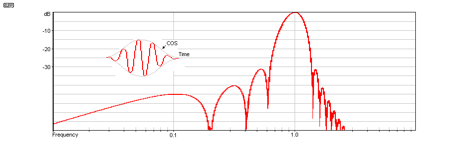
Firstly, a description of a cosine burst signal is in order. With a conventional tone burst generator, a considerable number of harmonics are generated. These extend to sub-audible frequencies, and excite resonances that have nothing to do with the actual test frequency. By gradually increasing the amplitude of each cycle of the test waveform, then decreasing it again using a cosine waveform envelope, these unwanted harmonics are minimised. They can never be eliminated, except by using a steady tone, in theory for an infinite duration. This is far longer than most people want to wait for test results.
Figure 1 shows the cosine burst envelope, along with the additional frequencies generated. The worst of these is 30dB below the fundamental, which is a considerable improvement on the more traditional 'rectangular' tone burst, where the signal is simply gated on for a number of cycles at full amplitude.
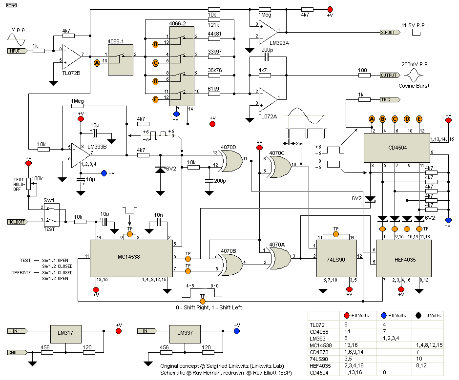
To achieve this waveform, 10 half cycles are used, with the amplitude increasing with each successive half cycle to the peak, then reduced back to zero. The repetition rate may be varied to suit the application, and the updated Linkwitz burst generator circuit is shown in Figure 2A. The original is retained for completeness.
The burst generator is not actually complex, but does require a fair bit of fiddling about to obtain the 10 half cycles needed, and apply the appropriate attenuation at each step to ensure that the cosine envelope is maintained.
The programmable attenuator consists of 5 sections of 4066 CMOS analogue switch (these are quad devices, so 3 are unused). The resistor values at the 4066 outputs are selected to provide the cosine envelope, feeding the virtual earth mixer stage that provides the output.
To trigger the attenuator control at each zero crossing of the input waveform, a comparator (LM393) is used to create a square wave, whose zero crossings are at the same time as the signal waveform. The XOR gate (A) is used to produce a 2us positive going pulse corresponding to each zero crossing of the input waveform. All remaining XOR gates are used as inverters.
The remainder of the logic is clocked by the incoming waveform, and the outputs drive the CMOS analogue switch controls. The entire circuit is normally inhibited by the repetition generator circuit, which is a simple timer. When the hold-off time expires, the next incoming signal zero crossing will start the cycle, allowing 10 half cycles to pass before switching off again. This sequence continues as long as the unit has an applied input signal.
Virtually any audio oscillator can be used to drive the burst generator, with the proviso that it must be capable of 1V peak to peak output level. Distortion is not important as long as it is within reasonable limits (less than 1% is preferred).
Ray's revised version is slightly more complex than the original, but has the advantage that the parts can actually be obtained.
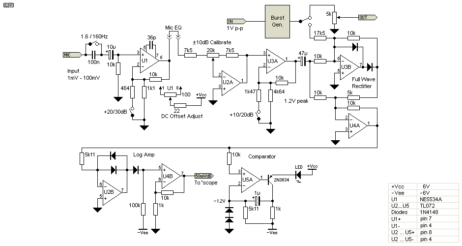
The microphone preamp is not intended for listening to, but still requires low noise. Figure 3 shows the circuit for the preamp. The signal is first amplified by the 5534 opamp which also has a switched gain, and optional equalisation can be applied. The next stage is a variable gain amp, and allows calibration of the preamp. This is followed by a switchable gain stage and a full wave precision rectifier to convert the AC mic waveform to DC. This is fed into a log amplifier with an output of 50mV / dB as shown. For posterity, the original version is still available here. Note that in the original, the resistor marked as 10//10 means two 10k resistors in parallel to give 5k.
For quick tests, the comparator stage can be used, and by observing the LED and adjusting the calibration control it is possible to determine relative frequency response without the use of an oscilloscope. Alternatively, a meter movement (with modified peak programme ballistics) could be used from the output of the log amplifier, using a suitable metering amp circuit.
There may be a small benefit in gating the microphone preamp to exclude room reflections, but great care is needed to ensure that the gating circuit can be adjusted to accommodate the measurement distances used, remembering that sound travels at around 343m/s, measurements at 1 metre will require a gate delay of about 2.9ms. This is not really necessary however, since the whole reason for using the cosine envelope is to minimise the generation and reflection of any frequency that is not the actual test frequency. Room reflections will normally be at a considerably reduced amplitude compared to the direct signal, so accurate results should be obtainable in all but the most adverse rooms.
An electret capacitor microphone is a cheap and remarkably accurate little device, but they are not known for tolerance to high SPLs. The FET preamp is usually very crude, and having no source feedback resistance will distort readily at modest sound pressure levels. To this end, Siegfried has gone to work on a standard capsule, and modified it so that it will work at standard test levels.
This is a redrawn version of Siegfried's drawing, and again the original is retained. The choice of preferred connection is yours. I tend to like the 3-wire version since it retains 'conventional' polarities, but the difference is minimal in practice.
Electret inserts are readily available from many suppliers, but there is good reason to use the Panasonic unit suggested if possible (although it is now superseded). They have very good frequency response, where some of the alternatives might look identical, but have relatively poor response by comparison. It would be nice if these microphones were available with some sort of calibration information as to frequency response and so on, but unless you are willing to pay through the nose, you will have to accept whatever you can get.
When I originally contacted Siegfried Linkwitz about re-publishing this project, he mentioned that some of the devices were obsolete, and that an update was needed. I have so far been unable to find commonly available devices that will allow the circuit to operate as intended, without either dropping the operating voltage to a single +5V supply (which I was unwilling to do), or using level shifters - again, not ideal, as complexity is increased. I have not given up, and will continue as time allows to investigate the alternatives. Meanwhile, the version Ray Hernan has supplied looks good, and short of using a microcontroller (which may not be fast enough) is probably as good as it will get.
The ability to add multiple bursts of 4 was also suggested, and I would like to include this as an option, however, this will add more complexity to what many will see as an already complex project. Ray has provided a very workable solution, as shown in Figure 2 (which replaces the original), and it is unlikely that further work will be done on the project.
This project is primarily the intellectual property of Siegfried Linkwitz, and is reproduced here with his permission. Commercial use is strictly prohibited without the written permission of Siegfried Linkwitz. The Figure 2a circuit diagram is the intellectual property of Ray Hernan, and is copyright © 2007. The redrawn versions of all schematics shown were drawn by Rod Elliott (ESP) and are copyright © 2008. Note that multiple versions of the same schematic reproduced on the ESP and Linkwitz Lab sites do not imply that the circuit, concept or drawings are freely distributable. Full copyright is retained by the various authors, based on their contribution(s) to the project.
Siegfried Linkwitz, Shaped Tone-Burst Testing, JAES, Vol. 28, No. 4, April 1980
A properly shaped tone burst is used to evaluate the dynamic behaviour of a loudspeaker within narrow frequency bands. The raised-cosine envelope of a five-cycle burst reduces the low frequency content of the test signal and confines the spectrum to a one-third octave width. The transient behavior of the loudspeaker is indicated by a change in the envelope of the burst signal. The frequency response of the loudspeaker is related to the maximum amplitude of the received burst. The relatively short duration of the burst preserves time domain information and gives a slightly smoothed frequency response. Discrimination against echoes is obtained from the short duration of the shaped tone burst. The influence of room reflections on the measurement is minimised.
A detailed circuit schematic for building a shaped tone-burst generator and peak detecting receiver is provided.
 Main Index
Projects Index Main Index
Projects Index |