
|
|
| Elliott Sound Products | Project 238 |
 Main Index
Projects Index Main Index
Projects Index
|
It's not every day that you suddenly find yourself needing a high voltage supply, but the day will come at some point for many experimenters. You might need to be able to test the breakdown voltage of transistors, operate a valve (vacuum tube) within an otherwise low-voltage circuit, or perhaps to perform an insulation test to ensure that your latest masterpiece is electrically safe. In these applications, there's no need for a great deal of current, with the examples mentioned only needing a couple of milliamps at most.
An option I've shown in a few projects is to use a small transformer in reverse, and by providing a voltage to the secondary, the voltage is much greater across the primary winding. If this is operated at 50/ 60Hz, the efficiency is rather poor, because the small transformer will be on the verge of saturation when it's operate 'backwards'. The solution is to use a higher frequency, typically something between 500Hz and 2kHz. Any higher than 3kHz is not a good idea, as iron losses in the core will start to become dominant. The transformer I tested with started to show increased hysteresis core loss above 3kHz.
While you may expect the transformer to 'sing', you'll need very good ears to hear it. I was able to detect some mechanical noise at 2kHz, but that required an improvised stethoscope. It would be wise to use resilient mounting if you think the noise may be a nuisance (it may be louder than mine with some transformers).
Warning: Although the circuits described have low output current, they can still deliver a very nasty bite that could prove fatal. Always treat any high voltage with due respect, even if you think it should be 'safe'. Without a load resistor, the output cap(s) can store energy for a long time, so ensure that you safely discharge the cap(s) before working on the secondary (high voltage) side of the circuit. By continuing and/ or building any circuit shown, you accept full responsibility for any injury suffered (including loss of life).
Ultimately, any step-up or step-down transformer is characterised by the turns ratio. When transformers are designed, the output voltage is per the nameplate rating with full load, resistive. A transformer rated for 230V input and 12.6V output at (say) 150mA will have a higher output voltage at a lower current. The transformer I used has an effective turns ratio of about 14.8:1, so the (unloaded) output voltage will be 230 / 14.8 = 15.54V RMS. The VA rating applies to the output, and the input VA will be greater than the nameplate rating (in this case up to about 3.5VA).
When the winding resistances are included (2 × 2.7Ω for the secondaries, 1kΩ for the primary), the output will be 13.9V with a 170mA load (determined by testing). The (simplified) equivalent circuit for the transformer is shown in each of the drawings below. When the transformer is reversed so the primary becomes the secondary and vice versa, the output voltage is lower than expected. If you were to inject exactly 12.6V RMS (at 50Hz), the output will be about 186V, not 230V. Needless to say, the same constraints exist for all transformers, regardless of the intended mains voltage, frequency or size.
When reversed, the secondary winding resistance limits the input current, and output current is similarly limited by the primary resistance. There are also additional losses that affect the performance, but these are (at least partially) mitigated by operating the transformer at a higher than normal frequency. Most of the circuits shown operate at around 700Hz, so magnetising losses are reduced and the core is not operated anywhere near the magnetic flux that would cause partial saturation (the main loss component in small transformers).
The primary (no load) current for my test 2VA transformer is 7.5mA, or around 1.75VA. This rises to a bit over 15mA at full load, around 3.45VA. This will always be the case with small transformers. All-in-all, these are pretty awful, but they serve their intended purpose despite their shortcomings. Used in reverse with a higher than normal frequency, they perform surprisingly well.
The circuits shown here have all been simulated, and several were constructed, or the equivalent circuit was tested by other means. Many tests were conducted, turns ratios measured and calculations performed to ensure that all circuits perform as claimed. Several tests were performed using Project 186 - Single Chip 25 Watt/ 8 Ohm Workbench Power Amplifier. This was ideal for injecting voltage/ current into the secondary to measure the voltage across the primary.
To learn more about transformers, I suggest that you read the series of articles that cover them in detail. Start with Transformers - The Basics (Part 1). The articles may appear daunting (there's a vast amount of information), but no-one else has covered the topic in as much detail. The articles cover almost everything you need to know, but assume 'conventional' wiring (i.e. where the primary is used as the primary - not reversed). The photo shows my test tranny - it's 43mm wide (across the top), 20mm deep and 35mm tall. It's typical of countless similar transformers available now. Older Australian enthusiasts will recognise the brand instantly.
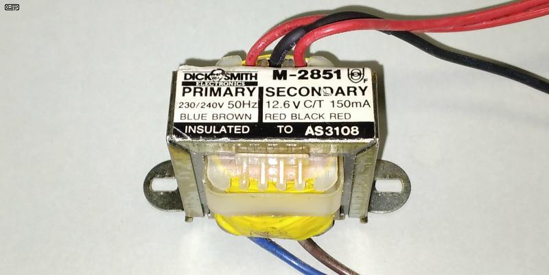
Above is a photo of the transformer I used for all tests - it's at least 20 years old, maybe 30. With an input of 230V, 50Hz, the output was 15.57V at no load, falling to 13.9V with a load of 80Ω (173mA). That indicates that the design was not optimised, so the nameplate ratings are nominal with a fairly wide tolerance. You can't expect much more from a component that is made as cheaply as possible. With no load, the primary current was 7.93mA, rising to 15.2mA with the 80Ω load.
I took just about every measurement possible, but not all are meaningful. Measuring the inductance is rather pointless (I did it anyway, but the answer is never useful), and no manufacturer provides this in a datasheet. I measured 28 Henrys at 100Hz, but that's nowhere near the real value (about 97H). From the no-load output voltage, one can determine the turns ratio, but even that is subject to errors if you don't use a 'true-RMS' meter. Transformers are not precision parts, and there will always be variations from one unit to the next. Theory can only take you so far when you use a transformer in reverse. Ultimately, you won't know how well it will work for you until you test it.
Consequently, you will see differences between the voltages claimed on the circuits that follow and what you get with your transformer. This is not a project to provide a perfectly regulated output with no noise and 100% predictable output voltage. It's intended to be used where you need a high voltage (300V or more) at the lowest possible cost in parts and time. Many readers will see applications for their projects, and others will never need anything even remotely similar.
There are a number of options for getting a high voltage, and the one you'd probably think of first is a switchmode boost design. These are superficially simple, but it becomes apparent fairly quickly that there are limitations. There's no doubt that a simple boost supply can develop very high voltages, but it's hard to get much usable current. The small inductors commonly used with boost supplies can't handle high voltages, and the output is referenced to the circuit common (typically 'ground'). Even if you were to get 100% efficiency, if you boost 12V to 300V (for example) and expect 5mA output, the average input current is 125mA. This applies to any boost converter of course, but the inductor will have to be specially made so it can withstand the voltage.

The circuit as shown is about as simple as you can get. The transformer is the one pictured above, and similar low-cost types are available from many suppliers. The primary is rated for 230V mains. It's being used backwards, so the primary is really the secondary. Operating at a higher frequency means that the core won't saturate, and by keeping the frequency fairly low we can use a cheap, commonly available opamp and equally common output transistors. C2 is a compromise, but for the transformer I used it was perfect. The ripple current is well below 100mA (typically less than 20mA). The 12.6/ 6.3V windings are designed to power heaters in valve (vacuum tube) circuits, and most (including the one I used) are 12.6V with a centre tap. One secondary winding is shown disconnected. It must be insulated to prevent a possible short circuit.
Note that Q1 and Q2 don't need a heatsink, but you may choose to add one. This applies to all circuits shown. It won't need to be large, and around 50×50mm flat sheet should be more than sufficient. The transistors should dissipate less than 100mW each, and without a heatsink they will get warm (still a comfortable temperature for a 'finger test'). If you add a heatsink, the transistor rear pads must be insulated from the heatsink with a silicone pad or similar (or you can use 'full pack' transistors if available).
You may wonder why a 6.3V winding is needed when we have a 24V supply. The opamp and output transistors can't swing to the full voltage, and we lose about 2V from the positive and negative excursions. That leaves a 20V p-p signal, which isn't a great deal higher than the rated peak output voltage (6.3 × 1.414 × 2, 17.8V p-p). For a small transformer to be able to deliver its rated voltage at rated current, the secondary voltage must be greater than 6.3V with no load - around 7V would be 'typical'. That means that you need at least 9.9V peak to get 325V peak output. The input is a squarewave (near enough), so peak and RMS are the same.
The advantage of this compared to a switchmode boost converter is that it operates at a relatively low frequency, and has no very fast transitions, keeping electrical noise low. Because the output can be fully isolated from the input (no shared connections) you have complete flexibility as to how it's wired into a circuit. It's also (quite deliberately) 'low-tech', making it easy to understand, and it doesn't need any specialised parts. Don't be tempted to use a large electrolytic capacitor for the output, as that will stress the drive circuit. You can get away with up to 10μF, but I wouldn't exceed that. Make sure that all capacitors used are within their voltage ratings - allow at least 20% 'reserve', so for 300V output, use caps rated for at least 360V (400V is the closest available in most ranges).
For the opamp, you can use a TL072, 4558, 4158 or similar. One half isn't used so it's connected in a way that ensures its inputs remain within the 'normal' range. Most common opamps will be fine in this role, but do not use one with an asymmetrical output, such as the LM358. It's fast enough, but the asymmetrical output will cause the drive current to be unbalanced, potentially causing partial saturation. The capacitor coupling (C2) should minimise any issues. You could also use a 741 opamp, eliminating the 'wasted' opamp in the package. Note that the pinouts for a single opamp are different from that shown.
While it's possible to get well over 300V DC output, it's not recommended because of the transformer. Its internal insulation is designed for a 230V AC sinewave, not a 700V or more squarewave. You can use two circuits and connect the outputs in series - for the example shown that gives you an output of around 600V DC. A voltage doubler is simpler (shown below).
The output isn't regulated, but you'll find that it will be within about 2% with light loading. I measured a drop from 308V to 298V when the load was changed from 470k to 235k (655μA to 1.27mA). The input current to the transformer was about 58mA, almost all of which was supplying the transformer losses. This is not intended to be efficient - it's utilitarian, and provides you with a cheap, simple way to get a high DC voltage from an existing supply. The current is limited, but it has enough for a 12AX7 in a guitar preamp (for example), and is likely to be the cheapest way to get the voltage you need.
Note that while I showed the circuit using a single 24V supply, it's just as happy with a ±12V supply. A ±15V supply will give you a higher output (around 380V DC). The output voltage is determined by the input swing to the transformer and the transformer ratio. You will need to experiment a bit, but like so many ESP projects, that's the whole idea. The 220μF coupling cap should ideally be rated for 35V, but you may get away with a 25V part (that's what I used, and it was fine).

Experimental circuits are the life-blood of DIY projects, and this is definitely no exception. The need (for me) was a simple way to get a 300V supply for transistor breakdown voltage testing. This is provided in the Project 31 transistor tester, but that's about to be retired. Since the power supply is being changed out for a SMPS to get more current, I needed a simple way to get the high voltage supply. These circuits were the result.
If you only have a single 12V supply available, the second opamp is used as an inverter, driving a second pair of output transistors. The transformer is then driven in push-pull, rather than single-ended. There's a small loss of voltage because there are two sets of voltage drops from the opamps and output transistors, but that won't usually be a problem. It might be possible to delete C2, but in general that's not recommended. Any DC in the transformer will cause partial saturation and excessive current. Note that you may need to reverse the polarity of C2 if it's wrong in your circuit.
IC power amps such as the LM1875 (which is readily available) or the TDA3020/30/40/50 (which are not, other than via unauthorised sellers) can 'simplify' the circuit. These power amps are just high-power opamps, so the circuit is the same, but you don't need external power transistors. A supply using these will be more expensive than the semi-discrete version, but it is convenient. You will need a small heatsink for the IC because they draw a relatively high quiescent current, but that's usually easy to include (a flat piece of aluminium of around 100×50mm should be sufficient). Having compared the 'power opamp' version with the boosted opamp (e.g. Fig. 1), I can say that it works, but it's hard to recommend overall. The TDA2050 I tried drew 100mA with 24V input, compared to less than 60mA for the Fig 1 circuit.
Because these devices are configured to have a gain of at least 20dB and operate in linear mode, you may see some low-level oscillation on the square wave output. Having tested the circuit fairly thoroughly, it's safe to say that any oscillation cannot be ignored. The Zobel network (R5 and C2) is mandatory, and without it the amp will oscillate and draw excessive current. Overall, this arrangement isn't really recommended, but a 'conventional' power amp (using the same IC) driven with a squarewave would be alright. This just adds more complexity for no real benefit.
The final version should be used if you need more current. I've shown it with the same transformer as the others, but this circuit wouldn't be worth the effort for only a few milliamps. With the right transformer you should be able to draw an output current of perhaps 100mA or more at 450V DC. That would require a transformer of at least 75VA. With the transformer shown, the simulator claimed an output of 630V, and that's close to what you'll get in reality with light loading. The voltage across the whole primary is (roughly) ±24V (i.e. 48V p-p), so the theoretical output voltage will be a bit over 660V RMS. Because it's a square wave, peak and RMS voltages are the same. The actual output voltage depends on the transformer's winding resistance and the load current.
Suitable MOSFETs are ubiquitous - the IRF510 is cheap (about AU$1.00), but you can use almost any TO-220 MOSFET that can handle at least 50V at a couple of amps or more. Old favourites are the IRF530/540 or MTP3055 which will work perfectly. The 40106 (or 74C14) is a hex Schmitt trigger/ inverter (14 pin), and unused sections should have their inputs grounded. A 4093 is also suitable (quad Schmitt trigger NAND gate, with the two inputs for each gate in parallel). You can operate gates in parallel for more MOSFET gate drive current, but that's not really necessary. Note that the (absolute) maximum supply voltage for CMOS is 18V, but 12V is preferred. The oscillator output duty-cycle should be as close to 50:50 as possible, but a small imbalance won't hurt anything because the frequency is much higher than normal, meaning that saturation issues are minimised. Much the same result can be obtained from a 'self-oscillating' converter, but they require another winding for feedback, and can be somewhat unpredictable. These used to be surprisingly common (I worked on them about 50 years ago), but a disadvantage is they are prone to mechanical noise. Early types were completely potted in an attempt to reduce the noise. For commercial applications a 'proper' SMPS would be used now, operating at 30kHz or more.
If you need a higher voltage, the output from any of the circuits can be re-configured as a voltage doubler. You save two high-speed diodes, but need an extra capacitor. This is a very simple way to get the voltage you need, without stressing the transformer's insulation. In my intended application, a voltage doubler is perfect, as I was after a 500V DC test voltage which was easily achieved.
The voltage doubler lets you get a much higher voltage without exceeding the maximum voltage for the transformer's winding. Of course, you can draw less current. The voltage doubler means that the input current is twice that for a bridge rectifier, so DC output current is halved. Voltage doublers are an easy way to get more voltage with a minimum of fuss. More importantly, the transformer's primary winding isn't pushed to a much higher voltage than it was designed for.
There's not much more to say about the circuits. If necessary you could use a larger transformer and a higher powered 'amplifier' circuit to get more current, and it may still be a lot cheaper than any other technique. A large part of the low cost is the ability to use a transformer that's readily available (preferably in your 'junk box'), and they will be safe because they're designed to be used with the AC mains. A switchmode version would need a custom coil/ transformer and a dedicated SMPS controller IC. These ICs are nearly all SMD now, making a Veroboard 'quick & dirty' circuit impossible. I used Veroboard for my tests.
Suitable transformers for low current are available from major suppliers for less than AU$10 each, so the total cost can be kept quite modest even if you have to buy all the parts. Although I've not shown a circuit, you can use a regulator on the low-voltage DC side, controlled by the high-voltage secondary. For the types of things a supply like this will be used for, it doesn't make much sense to make it more complex. As an alternative to a switchmode supply (which will be a custom design), this is a very cheap way to get a simple high voltage power supply.
The transformers shown assume a 230V primary. For countries where 120V is the standard, choose a transformer with a dual primary, which lets you operate the two windings in series to obtain a nominal 240V primary. Because the transformer is used in reverse, the 'primary' becomes the 'secondary', but convention dictates that the original designations should be used.
Remember that if you use (for example) a 2VA transformer, its secondary winding (used for the input) is designed for a maximum current of 158mA for a 12.6V transformer (VA/V). The primary current (used as the output) will be around 15mA. After rectification, that means that you should not draw more than 12mA (AC) from the secondary, which translates to a DC output of about 6mA. If you use a voltage doubler at the output, the DC output is reduced to around 3mA. You can easily work out the maximum current for any sized transformer this way.
The transformer can also be driven with a pair of switches (BJTs or MOSFETs) with a centre-tapped transformer (see Fig. 4). These used to be common, but using them at audio frequencies with (relatively) high current means there will almost always be some audible noise (mostly due to magnetostriction) - this a phenomenon where the laminations change their dimensions with the magnetic field. There's not much movement, but it's often enough to be audible. I heard no audible noise from the low power circuits described, other than by using an improvised stethoscope.
If you think you need a heatsink, a rough calculation for thermal resistance is 50/√A, where 'A' is the area in square centimetres. A piece of aluminium sheet 50×50mm has an area of 25cm² for each side, so the thermal resistance (to free air, both sides) is about 7°C/W. This isn't a precision calculation, but it's useful for small heatsinks, and worth remembering. Other than the IC power amp, you won't need a heatsink unless you draw more current than I've allowed for.
There are no external references, as few people seem to have devised anything along the lines of the circuits shown here. You may come across a circuit for a single transistor inverter (commonly known as a blocking oscillator), but these are a bit like two-stroke motors and teenagers - they go for no reason and stop for the same. Unless the magnetic circuit is designed for the application, the results are unpredictable, regulation is woeful, and the primary current will be much higher than the Fig. 1 circuit. I don't link to circuits that will be disappointing or that don't work.
| Main Index
Projects Index |
| Copyright Notice. This article, including but not limited to all text and diagrams, is the intellectual property of Rod Elliott, and is Copyright © 2023. Reproduction or re-publication by any means whatsoever, whether electronic, mechanical or electro-mechanical, is strictly prohibited under International Copyright laws. The author (Rod Elliott) grants the reader the right to use this information for personal use only, and further allows that one (1) copy may be made for reference while constructing the project. Commercial use is prohibited without express written authorisation from Rod Elliott. |