
|
|
| Elliott Sound Products | P215 - [Project 27 Revisited] |

| Please Note: PCBs are available for both the power amp and preamp (P27A and P27B Respectively). Click the image for details. |
The P27 guitar amplifier has been very popular over the years, with hundreds of PCBs sold. One of the things that may not be to everyone's liking is the output power. It's rated for 100W into 4Ω, and for many people that's far more than they need. While the level can be reduced with the master volume control, it's still a big, powerful amplifier. Many professional players only use small amps (between 30-50W is common), and for practice you generally need even less. To address this, the P27 guitar amp is now 'revisited' as Project 215, to reduce the power to something more realistic for players who simply don't need ear-bleeding levels.
Most of the circuitry is very similar, but the differences are sufficient to warrant a new project page. The power amp only has two output transistors, and four 5W resistors aren't used (two are replaced with links). The supply voltage is reduced from the previous ±35V to ± 22V, obtained from a 15-0-15V transformer. While it may seem tempting to use an IC amplifier such as the LM3886, these have a small contact area with the heatsink, and in my experience they are not at all suitable for a guitar amp with master volume. Major guitar amp manufacturers have used these or similar ICs, and failure is very common. The power amplifier is close to bullet-proof, even with two transistors removed.
The tone controls, gain and overload characteristics are very individual, and the ideal combination varies from one guitarist to the next, and from one guitar to the next. There is no amp that satisfies everyone's requirements, and this offering is no exception. The preamp is now at Revision-A, and the complete schematic of the new version is shown below. The fundamental characteristics are not changed - it still has the same tone control 'stack' and other controls, but now has a second opamp to reduce output impedance and improve gain characteristics.
One major difference from any 'store bought' amplifier is that if you build it yourself, you can modify things to suit your own needs. The ability to experiment is the key to this circuit, which although presented in complete form, there is every expectation that builders will make modifications to suit themselves. Of course there will be people who don't like the circuit (some without even trying it), and it is not intended to be the 'last word' - especially the preamp. There are many constructors (of the 100W version) who are very happy with it pretty much as shown, but there will always be people who are after something different. There's not much that limits the changes that you can make to the preamp to get the sound you want, but it is what it is - a 'solid state' preamp. Don't expect it to sound like a valve preamp, because it's not!
The power amp is rated at 40W into a 4Ω load, as this is typical of a 'combo' type amp with two 8Ω speakers in parallel. Alternatively, you can run the amp into a 'quad' box (4 x 8Ω speakers in series parallel - see Figure 5 in Project 27b, the original article) and will get about 20 Watts (but it will still be loud!. For the more adventurous, 2 quad boxes and the amp head will provide 40W, but will be much louder again than the twin. This used to be a common combination for guitarists, but it makes it hard for the sound guy to bring everything else up to the same level. Many players have switched to smaller amps (which may also help to protect their hearing).
Note: This is a revised version of the updated 100W guitar amp, and although there are a great many similarities, there are some substantial differences. The reduction of output power means that quite a few things change, so this 'new' version is warranted. PCBs are available for both the power and preamp. The original version of this project has the speaker box details - for these, see Project 27b. If you have the skills to make your own chassis and a complex timber box, this version is ideally suited to a 'combo' style amp.
The P27 guitar amp & preamp have been popular projects from first publication, and they are both solid and reliable performers that do not sacrifice sound. Fairly obviously, there is no single guitar amp that will suit everyone, but with the ability to make changes you can usually get a combination that works for you. The advantage of the DIY approach is that you can change things to suit your instrument and playing style, something that is far more difficult with a 'store-bought' amplifier. With some of the latest offerings using SMD (surface mount devices) on very compact PCBs, service or modification is often very difficult. If you build your own, you can make changes any time you want to.
When replacing guitar strings, never do so anywhere near an amplifier (especially a valve amp), nor close to a mains outlet. Because the strings are thin - the top 'E' string in particular - they can easily work their way into mains outlets, ventilation slots and all manner of tiny crevices. The springiness of the strings means that they are not easily controlled until firmly attached at both ends. This is very real - click here for a photo of an Australian mains plug that was shorted out by a guitar string. |
It's worthwhile to read the article How Much Level Do You Get From Guitar Pickups?. From that, you can see why the first gain stage has less gain than you'd expect, and why tone controls favour higher frequencies. The article only covers the guitars I have, but it is fairly realistic for most guitars and basses. There will always be some that have more or less output, but expect most to be within the ranges shown in the oscilloscope captures.
A photo of the Revision-A preamp is shown below, and it is simply a slightly modified version of the one published in Project 27. You'll see that there are two dual opamps. I recommend that you use an OPA2134 for the front-end, followed by a 4558 (a mainstay of guitar amps and pedals for a very long time. The preamp has proven to be very popular, and it has no 'bad habits'. In particular, it can produce heavy overdrive with no tendency towards 'blocking' (Note 1) - an undesirable characteristic where a high-level signal causes momentary shut-down of one or more gain stages. It has high gain with the values shown, but it's also easily tamed if you don't need (heavy) distortion. Reducing the gain also reduces noise.
¹ 'Blocking' is caused when the output of a gain stage is of sufficiently high level to cause the following circuit to (momentarily) cut off the signal. It's easily achieved with valve, JFET and BJT (bipolar junction transistor) circuits (see Designing With JFETs - Section 9) for details of how this happens. Undesirable behaviour can occur with some opamps without due care. The preamp and power amp featured here will both come out of severe overdrive with no recovery delay.
These characteristics are identical to the original P27 preamp (and power amp). Both are designed to ensure clean overdrive without 'artifacts' that ruin the sound under heavy overdrive. Most commercial designs get this right, but not all DIY projects are well thought out. This is particularly true of designs using JFETs, which can (and do) often misbehave when driven to clipping (overdrive). Note that the PCB shown below is fully populated for P27B, and some parts are removed for this version.
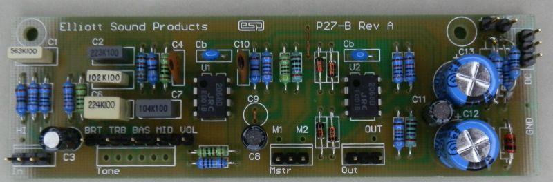
Figure 1 - P27B Guitar Pre-Amplifier Board (Revision A)
The preamp circuit is shown in Figure 2, and has a few interesting characteristics. This is a deliberately simple design that provides a wide tonal range. The gain structure is designed to provide a lot of gain, which is ideal for those guitarists who like to get that fully distorted 'fat' sound. Not everyone will like the diode clipping circuit, and if that describes you, then leave it out (omit R14 and D2-D4, and replace R13 with a wire link). It's easy to set up the preamp to have exactly the right amount of gain for you - nothing is 'set in stone', and almost everything can be tailored to your preferences.
The effects loop is designed to allow you to use an external distortion unit and/ or other effects units designed for 'line level'. Note that when the photo was taken, D1 and D3 are installed, but for best performance D1 and D3 are replaced with links. These changes reduce the clipping level, because the power amp needs less input for full power than the 100W version. The maximum output level before the clipping diodes start to work is around 350mV RMS, so external effects must be able to handle ~700mV RMS without distorting.
With a couple of simple changes, the preamp can be set up to suit just about any style of playing. Likewise, the tone controls as shown have sufficient range to cover almost anything from an electrified violin to a bass guitar - The response can be limited if you wish (by experimenting with the tone control capacitor values), but I suggest that you try it 'as is' before making any changes. (See below for more info.)
An alternative to the zener regulators is shown in Figure 8, and if you choose to use that circuit, the two zener diodes (D5, D6) are omitted, and R19, R20 are replaced with wire links. This will be helpful if you decide to build in any effects (e.g. reverb or tremolo) where the zener regulators will be unable to provide enough current.
Figure 2 - Guitar Pre-Amplifier (P27B)
From Figure 2, you can see that the preamp uses two dual opamps. The last stage is a buffer with a gain of two, and maintains a low output impedance after the master volume control. The gain can be increased by reducing the value of R18, or reduced by increasing the value. As shown, with a typical guitar input, it is possible to get a very fat overdrive sound by winding up the Volume, and then setting the Master for a suitable level. The overall frequency response is deliberately limited to prevent extreme low-end waffle, and to cut the extreme highs to help reduce noise and to limit the response to the normal requirements for guitar. C9 is not used, and should be replaced with a link as shown.
I used NJM2068 opamps, somewhat less known than most others, but they have the same noise as a NE5534 and draw much less current. If you use 4558 (or TL072) opamps, you may find that noise is a problem - especially at high gain with lots of treble boost. I suggest that you use an OPA2134 for U1 - a premium low-noise audio opamp from Texas Instruments (Burr-Brown division), you will then find this quite possibly the quietest guitar amp you have ever heard (or not heard  ). At any gain setting, there is more pickup noise from my guitar than circuit noise. An even quieter opamp is the LM4562, and although it has bipolar transistor inputs, it should work well (although I've not tried it). Bipolar input opamps are less well suited to high impedances than JFET input types, and can be noisier than expected. A TL072 opamp is suggested for U2, although I used a second NJM2068.
Note: With bipolar input opamps, I suggest that you add the extra capacitor (CX), in series with the output of the volume pot. This prevents pot noise due to the small DC offset created by the opamp's input bias current. It's not needed if you use FET input opamps.
The gain structure of a guitar amp is important. For clean playing you need relatively low gain, and the first stage should be the primary gain stage. That keeps noise low at lower volume settings, but it's important that the first stage doesn't contribute significant distortion. This will always be a balancing act, which is made a little harder with opamps than valves because the supply voltage is much lower. With a 150V supply, a valve may be able to swing ±40V peak easily, but opamps are limited by the supply voltage - typically ±15V.
Notes:
1 - IC pinouts are industry standard for dual opamps - pin 4 is -ve supply, and pin 8 is +ve supply.
2 - Opamp supply pins must be bypassed to earth with 100nF caps (preferably ceramic) as close as possible to the opamp itself.
3 - Diodes are 1N4148, 1N914 or similar.
4 - Pots should be linear for tone controls, and log for volume and master.
The power supply section (bottom left corner) connects directly to the main ±22V power amp supply. Use 15V/ 1W zener diodes (D5 and D6). The preamp PCB accommodates a zener diode regulated supply, which means that regulator ICs aren't required. If you's rather use a 'proper' regulated supply, see Figure 8 (or Figure 9 for the 100W version).
The pin connections shown (either large dots or 'port' symbols) are the pins from the PCB. Normally, all pots would be PCB types, and mounted directly to the board. For a DIY project, that would limit the layout to that imposed by the board, so all connections use wiring. It may look a bit hard, but is quite simple and looks fine when the unit is completed. Cable ties keep the wiring neat, and only a single connection to the GND point should be used (several are provided, so choose one that suits your layout).
If you don't need all the gain that is available, simply increase the value of R6 (3.3k). For even less noise and gain, increase R11 (3.3k) as well. For more gain, decrease R11 - I suggest a minimum of 2.2k here. With the values shown in Figure 2, maximum 'mid band' sensitivity is about 3mV input for full output (40W into 4Ω). This maximum gain is achieved with all controls at maximum, and it's normally lower when the tone controls are dialed back to more realistic settings. The gain structure is set up so that the maximum input level without clipping the input preamp is about 650mV peak. I've pushed the input preamp hard enough that it will clip the peaks to test the audibility of momentary clipping, and it's doubtful that it will cause any issues. If you have a guitar with high output pickups, R6 should be increased (3.9k or 4.7k will cover most guitars).
If the bright switch is too bright (too much treble), increase the 1k resistor (R5) to tame it down. Reduce the value to get more bite. The tone control arrangement shown will give zero output if all controls are set to minimum - this is unlikely to be a problem in use, but be aware of it when testing. Many 'name brand' guitar amps have the same characteristic.
The diode network at the output is designed to allow the preamp to generate a 'soft' clipping characteristic when the volume is turned up. Because of the diode clipping, the power amp needs to have an input sensitivity of about 450mV for full output, otherwise it will not be possible to get full power even with the Master gain control at the maximum setting. As shown in Figure 3, the power amp has an input sensitivity of ~450mV for full output into 4Ω, and about 300mV for full power (~20W) into 8Ω.
Make sure that the input connectors are isolated from the chassis. The earth isolation components in the power supply help to prevent hum (especially when the amp is connected to other mains powered equipment). The amp has a lot of gain, and any seemingly minor wiring errors can create a great deal of unwanted noise.
If problems are encountered with this circuit, then you have made a wiring mistake ... period. A golden rule here is to check the wiring, then keep on checking it until you find the error, since I can assure you that if it does not work properly there is at least one mistake, and possibly more. In particular, check that all resistors and capacitors are in the right places, and look carefully for solder bridges between adjacent pads and missed or 'dry' solder joints.
The input, effects and output connections are shown in Figure 3.
Figure 3 - Internal Wiring
The connections shown are very similar (ok, virtually identical ) to those used in my prototype. Noise is low, but when used at full gain (maximum volume, master gain set to desired level) there will always be some noise - high gain comes with noise (hiss), and it's not possible to have very high gain and no audible noise. All connectors must be fully insulated types, so there is no connection to chassis. This is very important!
You will see from the above diagram that I did not include the 'loop breaker' circuit shown in the power supply diagram. For my needs, it's not required, for your needs, I shall let you decide. If you choose to use it, then the earth (chassis) connection marked * (next to the input connectors) must be left off, and replaced with a 100Ω resistor with a 100nF capacitor in parallel. This is usually enough to prevent earth/ ground loop hum.
Potentiometer Wiring
Because the pot wiring can be confusing, the connections are shown above viewed from the rear, with colour-coding so each connection can be traces easily. Once the wires for the tone and volume pots are in place, there are only four wires (excluding 'Bright' and ground) that you need to worry about. These connect to the PCB with the PCB termination names reproduced above (i.e. Vol, Bas, Mid and Treb). The view is from the rear of the pots, just as you'll see them when running the interconnections. This should make wiring the pots much less stressful.
A few important points ...
One thing that will be needed is a shield between the power amp and the preamp. Depending on the parts you use to set the gain, you may have a total preamp gain of up to ×400 (52dB) at around 6kHz, so it's easy to get oscillation if the input jacks pick up even a tiny signal from the speaker wiring. A secondary shield around the input jacks is also recommended.
Figure 4 - Tone Control Response
The graphs show the tone control response, with R6 and R11 at 3.3k, and the output taken from the 'top' of the Master gain control. The three controls are varied in 25% increments. It doesn't include the action of the 'Bright' switch, which can increase the gain at 10kHz to 57dB (×700) with the treble pot at maximum. The graphs also show the gain of the preamp, with an average value of around 40dB (×100). This varies with frequency, with high frequencies getting more gain overall than bass and midrange. This helps to compensate for the natural reduction of output from guitar pickups at higher frequencies. After the Master gain control and the final gain stage, the gain is increased by a further 6dB.
As noted above, if you don't need so much gain, increase the values of R6 and/ or R11. The default value is 3.3k (giving each stage a gain of just under ×22), but you can adjust them to suit your needs. Even with this much gain, the first stage can handle an input voltage of over 400mV RMS without clipping. If you expect to experiment with these resistors, use PCB pins or similar to let you change the resistors without damaging the PCB.
There's a natural 'scoop' centred around 450Hz, which is almost cancelled out when the midrange pot is at maximum. This is very common with guitar amps, as it seems to provide good control at the frequencies that guitarists prefer. Most 'name brand' amps have very similar response curves. Few commercial guitar amps have the ability to get flat response, and the controls almost always add tonal colouration.
As shown, the preamp is just as usable for bass or electric piano as for rhythm or lead guitar. The main change that you may consider is to delete the clipping diodes (unless fuzz bass/piano is something you want). Delete R14, D2 and D4, but the remainder of the circuit is (more-or-less) unchanged. It will be helpful if R6 and R11 are increased in value, since you probably don't need extremely high gain. These two resistors can be up to 10k, giving an input sensitivity of about 20mV for full output (depending on tone control settings of course).
You may also want to experiment with the tone control caps - I shall leave it to the builder to decide what to change, based on listening tests. A 40W amp isn't very useful for bass, but it's probably fine for practice. If you need more power, you could use the preamp section as shown, but send the output (via the 'PRE OUT' jack socket) to one or more external 100W power amplifiers.
The power amp board has remained essentially the same since it was first published in 2002. It's been a reliable performer from the outset, and there's no reason to change it. The photo below shows a fully assembled board, populated for the 40W version. Still using TIP35/36C transistors, the output stage remains serious overkill. This ensures reliability under the most arduous stage conditions. No amplifier can be made immune from everything, but this does come close. It makes no sense to redesign the PCB for this version, because the board is easily modified to suit the lower power.
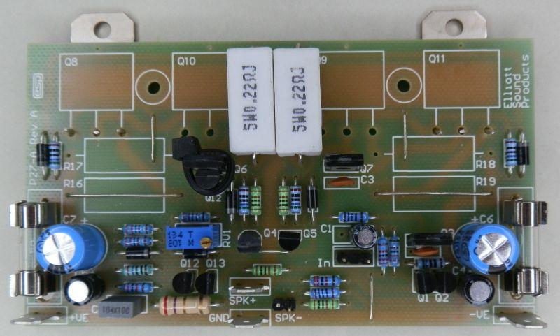
Figure 5 - P27 Guitar Power Amplifier Board (40W Version Omits 4 × 5W Resistors and 2 × Power Transistors)
You can see that the power transistors are mounted at the outside edges of the board to provide more space between them. This may come as a surprise, but wider spacing prevents each transistor from transferring heat to the other, and should help with cooling if the heatsink is marginal. Unfortunately, because there are only two power transistors, you can't use a metal bar or transistor clamp. The transistors must be installed so you can get to the mounting tabs to screw them to the heatsink. You will need to provide mounting for the PCB, or it will vibrate and eventually break the power transistor leads. A short spacer can be used under the PCB mounting holes, but make sure that the transistors make perfect contact with the heatsink (with insulating washers of course). I normally never recommend silicone pads, but with a low power amplifier such as this, even the poor thermal conductivity of silicone will be sufficient, but only if you have a good heatsink. The worst-case dissipation is only 10W for each transistor, and that will never be on a continuous basis in use.
The power amp includes basic current limiting protection - the two little groups of components including Q4 and Q5. This version is not significantly different from the 'normal' version of the P27 power amp. Because it runs from a lower voltage, several parts aren't needed. It still provides a 'constant current' (i.e. high impedance) output to the speakers - this is achieved using R23 and R26. Note that with this arrangement, the gain will change depending on the load impedance, with lower impedances giving lower power amp gain. This is not a problem, so may safely be ignored.
Should the output be shorted, the constant current output characteristic will provide an initial level of protection, but is not completely foolproof. The short circuit protection will limit the output current to a relatively safe level, but a sustained short will cause the output transistors to fail if the amp is driven hard. The protection is designed not to operate under normal conditions, but will limit the peak output current to about 5 Amps. Under these conditions, the internal fuses (or the output transistors) will probably blow if the short is not detected in time. If you use the recommended Speakon connectors (for the amp and speaker), there is little or no chance of a short ever happening. They are isolated from the chassis by design.
Figure 6 - Power Amplifier (P27A)
Figure 6 shows the power amp PCB circuit diagram. Note that R26 does not mount on the board. See Figure 3 to see where this should be physically mounted. The bias current is adjustable, and should be set for about 25mA quiescent current (more on this later). The recommendation for power transistors has not been changed from the 100W version. They are chosen because they are both economical and extremely rugged devices, and will provide excellent reliability under sustained heavy usage.
Note that the value of C2 has been increased to 470pF (it was shown as 220pF) to ensure stability. Because the output transistors don't have emitter resistors (as used in the 100W version), this changes their characteristics and that may cause the amp to oscillate. The chance of oscillation depends on the high-frequency gain (ft) of the transistors you use, and it can vary somewhat from one batch to another.
 |
As shown, the power transistors will have an easy time driving any load down to 4Ω. If you don't use the PCB (or are happy to mount power transistors off the board), you can use TO3 transistors for the output stage. MJ15003/4 transistors are very high power, and will run cooler because of the TO-3 casing (lower thermal resistance). Beware of counterfeits though! There are many other high power transistors that can be used, and the amp is quite tolerant of substitutes (as long as their ratings are at least equal to the devices shown). The PCB can accommodate Toshiba or Motorola 150W flat-pack power transistors with relative ease if you wanted to go that way. |
At the input end (as shown in Figure 3), there is provision for an auxiliary output, and an input. The latter is switched by the jack, so you can use the 'Out' and 'In' connections for an external effects unit. Alternatively, the input jack can be used to connect an external preamp to the power amp, disconnecting the preamp.
A pair of speaker connections allow up to two 8Ω speaker cabinets (giving 4Ω). Do not use less than 4Ω loads on this amplifier - it is not designed for it, and it will not give reliable service!
The low value (0.22Ω and 0.1Ω [R26]) resistors must be rated at 5W. They will get warm, so mount them away from other components. Needless to say, I recommend using the PCB, as this has been designed for optimum performance, and the amp gives a very good account of itself. So good in fact, that it can also be used as a hi-fi amp, and it sounds excellent. If you were to use the amp for hi-fi, the bias current should be increased to 50mA. Ideally, you would use better (faster / more linear) output transistors as well, but even with those specified the amp performs very well indeed.
Make sure that the bias transistor is attached to one of the drivers (the PCB is laid out to make this easy to do). A small quantity of heatsink compound and a cable tie will do the job well. The diodes are there to protect the amp from catastrophic failure should the bias servo be incorrectly wired (or set for maximum current). All diodes should be 1N4004. A heatsink is not needed for any of the driver transistors.
The life of a guitar amp is a hard one, and I suggest that you use a decent heatsink, since it is very common to have elevated temperatures on stage (mainly due to all the lighting), and this reduces the safety margin that normally applies for domestic equipment. The heatsink should be rated at no more than 2°C/ Watt to allow for worst case long term operation at up to 40°C (this is not uncommon on stage).
Make sure that the speaker connectors are isolated from the chassis to keep the integrity of the earth isolation components in the power supply, and to ensure that the high impedance output is maintained. Although phone jacks are the most common for guitar amps, it's better to use XLR or (preferably) Speakon connectors because they can't easily be shorted and are far more rugged. The amp can also be built as a 'combo', with the amp and speaker(s) in the same cabinet. The speakers can be hard-wired for a combo, but a connector is preferred.
WARNING - Do not attempt construction of the power supply if you do not know how to wire mains equipment.
The power supply is again nice and simple, and doesn't use IC regulators for the preamp (details are on the preamp schematic in Figure 2). There may be situations where you'd prefer to use regulator ICs, and that's covered further below. The power transformer can be a toroidal for best performance, but a conventional (E-I) tranny will do just fine. You may wonder why I suggest an 80-100VA transformer for a 40W amp. With anything smaller, the supply voltages will sag alarmingly when any power is demanded, and the larger transformer provides 'stiffer' supply rails. In addition, the power drawn by a guitar amp can easily exceed the ratings for smaller transformers. You can use a 60VA transformer, but the supply rails will sag badly under load, and this may affect the preamp regulators, allowing supply noise to intrude. For the same reason, I recommend more capacitance than is shown for the original P27 power supply.
|
Do not use a higher voltage than shown - the amplifier is designed for a maximum loaded supply voltage of ±22V, and this must not be exceeded. Normal tolerance for mains variations is ±10%, and this is allowed for. The transformer must be rated for a nominal 15-0-15 volt output, and no more. If you don't need the full 40W, use an 8Ω speaker. This can be either a single driver or a pair of 4Ω drivers in series. |
Figure 7 - Power Supply
The transformer rating should be 60VA (2A) minimum, although I suggest 80VA is more appropriate. There is no maximum, but the larger sizes start to get very expensive. Anything over 120VA is overkill, and will provide no benefit. A slow-blow fuse is needed if a toroidal transformer is used, because these have a much higher inrush current at power-on than a conventional transformer. Note that the 500mA rating is for a 'traditional' E-I transformer operating from 220 to 240 Volt mains and is suitable for an 80-100VA transformer - you will need a 1 Amp fuse for operation at 120 volts. If a toroidal transformer is used, the fuse should be 1A slow-blow (230V) or 2A slow-blow (120V).
Always use good quality electrolytics (25V minimum voltage rating, preferably 35V at 105°C types), since they will also be subjected to higher ripple current and temperature than a similar hi-fi application. The bridge rectifier should be at least a 10A type that can be mounted to the chassis (with thermal compound). Although Figure 7 shows 6 × 2,200µF filter caps, you can use a pair of 4,700µF caps instead. 6 × 2,200µF caps is my preferred option, as it's better than a pair of 4,700µF caps and should be cheaper as well.
The earth isolation components are designed to prevent hum from interconnected equipment, and provide safety for the guitarist (did I just hear 3,000 drummers asking "Why ??"). The 10Ω resistor stops any earth loop problems (the major cause of hum), and the 100nF capacitor bypasses radio frequencies. The bridge rectifier should be rated at least 5A, and is designed to conduct fault currents. Should a major fault occur (such as the transformer breaking down between primary and secondary), the internal diodes will become short circuited (due to the overload). This type of fault is extremely rare, but it is better to be prepared than not.
Another alternative is to use a pair of high current diodes in parallel (but facing in opposite directions). This will work well, but will probably cost as much (or even more) than the bridge.
All fuses should be as specified - do not be tempted to use a higher rating (e.g. aluminium foil, a nail, or anything else that is not a fuse). Don't laugh, I have seen all of the above used in desperation. The result is that far more damage is done to the equipment than should have been the case, and there is always the added risk of electrocution, fire, or both.
|
| Please be aware that the above 'earth loop breaker' may be unlawful where you live, and it may cause the guitar amp to fail a PAT (portable appliance tester) test due to the effective resistance in the earth lead (between the circuitry and chassis). It is the responsibility of the constructor to determine whether the (admittedly small) risk is worthwhile, and be aware that 'loop breaker' may cause a PAT test to fail - depending on how the test is applied. The chassis must be connected directly to the incoming earth lead. The loop breaker will only ever become active if there is a short between the primary and secondary of the power transformer. Such failures are very uncommon, and despite my reservations I have included the circuit because such failures are so uncommon. The transformer you use must be a quality unit from a reputable supplier! |
In some cases you may wish to provide a regulated ±15V supply that can provide a bit more current than the default zener regulated supply on the PCB. This is what I used to power a couple of built-in effects that will be published shortly. The supply is based on the Project 05-Mini, but with a few parts omitted and the addition of two Schottky diodes.

Figure 8 - ±15V Regulated Power Supply Based on P05-Mini (±22V DC Inputs)
The input rectifier diodes are omitted, with D1 and D4 replaced by links (do not install links in the D2-D3 positions!). R1 and R2 are replaced by Schottky diodes, with C1 and C2 omitted from the board. The diodes prevent the DC input from being influenced by the ripple on the main supply, and keep the ripple across C3 and C4 down to about 100mV RMS with a load of 100mA. The diodes also prevent the DC into the regulator ICs from falling below 20V, even with full overdrive on the power amp.
If you use this arrangement, the DC outputs connect to the P27B board normally, but R19 and R20 are replaced with wire links, and the two zeners (D5 and D6) are omitted. The 10Ω resistor shown in Figure 3 is relocated to the 'GND' terminal on the P05-Mini board. To use the P05-Mini with the standard 100W P27A power amp, use the following circuit.

Figure 9 - ±15V Regulated Power Supply Based on P05-Mini (±35V DC Inputs)
D1 and D4 are retained, but R1 and R2 are replaced with 5.1V 1W zener diodes. The zeners reduce the input voltage to ±30V to provide protection tor the regulator ICs. These have a rated maximum input of 35V, and the zeners reduce the voltage to a safer maximum. The maximum recommended current is 100mA, and that will result in zener dissipation of 0.5W, and regulator IC dissipation of 1.5W. The regulators will need a small heatsink if you draw more than 40mA for the preamp and other circuitry.
Electrical Safety
Once mains wiring is completed, use heatshrink tubing or other means to ensure that all connections are inaccessible. Exposed mains wiring is hazardous to your health, and can reduce life expectancy to a matter of a few seconds!
Also, make sure that the mains lead is securely fastened, in a manner acceptable to local regulations. Ensure that the earth lead is longer than the active and neutral, and has some slack. This guarantees that it will be the last lead to break should the mains lead become detached from its restraint. Better still, use an IEC mains connector and a standard IEC mains lead. These are available with integral filters, and in some cases a fuse as well. A detachable mains lead is always more convenient than a fixed type (until your 'roadie' loses the lead, of course). You will never do such a thing yourself.
The mains earth connection should use a separate bolt (do not use a component mounting bolt or screw), and must be very secure. Use washers, a lock washer and two nuts (the second is a locknut) to stop vibration from loosening the connection.
If you do not have a dual output bench power supply
Before power is first applied, temporarily install 22Ω 5W wirewound 'safety' resistors in place of the fuses. Do not connect the load at this time! When power is applied, check that the DC voltage at the output is less than 1V, and measure each supply rail. They may be slightly different, but both should be no less than about 15V. If widely different from the above, check all transistors for heating - if any device is hot, turn off the power immediately, then correct the mistake.
If you do have a suitable bench supply
This is much easier! Do not connect a load at this time. Slowly advance the voltage until you have about ±20V, watching the supply current. If current suddenly starts to climb rapidly, and voltage stops increasing then something is wrong, otherwise continue with testing. (Note: as the supply voltage is increased, the output voltage will fluctuate initially, then drop to near 0V at a supply voltage of about ±5V or so. This is normal.) Remember that the design supply voltage is ±22V, but this can be a bit higher or lower during testing.
Once all is well, connect a speaker load and signal source (still with the safety resistors installed), and check that suitable noises (such as music or tone) issue forth - keep the volume low, or the amp will distort badly with the resistors still there if you try to get too much power out of it.
If the amp has passed these tests, remove the safety resistors and re-install the fuses. Disconnect the speaker load, and turn the amp back on. Verify that the DC voltage at the speaker terminal does not exceed 100mV, and perform another 'heat test' on all transistors and resistors.
When you are satisfied that all is well, set the bias current. Connect a multimeter between the collectors of Q8 and Q11 - you are measuring the voltage drop across the two 0.22Ω resistors (R20 and R21). The desired quiescent current is 25mA, so the voltage you measure across the resistors should be set to 11mV ±2mV. The setting is not overly critical, but at lower currents, there is less dissipation in the output transistors. Current is approximately 2.3mA/ mV, so 11mV gives 25mA.
After the current is set, allow the amp to warm up, and readjust the bias when the temperature stabilises. This may need to be re-checked a couple of times, as the temperature and quiescent current are slightly interdependent. When you are happy with the bias setting, you may seal the trimpot with a dab of nail polish.
Note: If R22 gets hot or burns out, the amplifier is oscillating! This is invariably because of poor layout, inadequate (or no) shielding between preamp and power amp, or use of unshielded leads for the amplifier input. Please see Project 27B for the box designs and other useful info.
Having (finally) finished my prototype, I can include a couple of photos of the complete amplifier, but with the top removed so you can see inside. The chassis was made from 2.5mm aluminium sheet, with square section and angle used fo join the plates together. The assembly uses both screws and rivets, as some panels will never have to be removed individually.
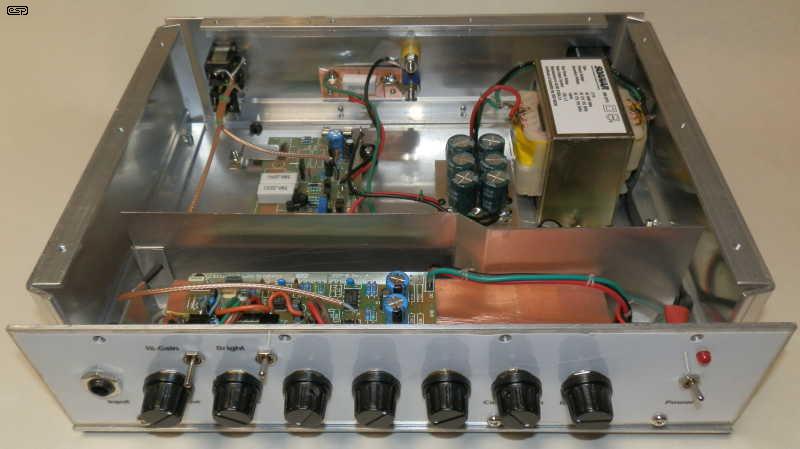
Photo From Front Of Amplifier
Something that isn't visible in the photo is hinted at on the front panel. There are two additional controls, one for compression (sustain) and the other for distortion. These are integrated, and the effect can be very pleasing. I've even managed to get a note to feed back (infinite sustain) at an SPL of only around 75dB. With the combined controls, it's possible to get very subtle distortion that doesn't fade out quickly. The level is kept constant by the compressor (actually a limiter) that keeps the level constant into the distortion circuit. This unit will be a project in its own right shortly.
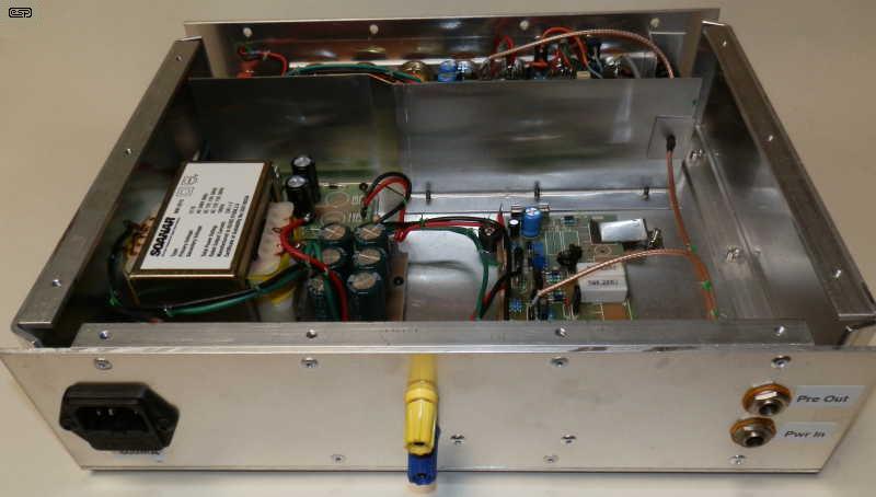
Photo From Rear Of Amplifier
The rear panel shows an unusual speaker output arrangement, a pair of banana sockets. This was done because I use banana plugs on most of my speaker leads, and saved me from making a separate lead just for the guitar amp. You can also see the preamp-out and power amp input sockets. These connect the preamp directly to the power amp when nothing is plugged in.
It's not very clear from the photos, but I reverted to my original training for cable management. Everyone uses cable-ties these days, but they look ugly, while the waxed string used to lace the cables (not quite to MIL-SPEC standards, but pretty close) has that 'old world' charm and looks much neater. All mains wiring is completely isolated by heatshrink tubing.
 Main Index
Projects Index
Main Index
Projects Index