
|
|
| Elliott Sound Products | Project 212 |
This is a rather specialised piece of test equipment, as it is designed for (mainly) low voltages but very high impedance (typically five to fifty times that provided by affordable digital multimeters). It's completely analogue, but it's intended to be used with a digital multimeter at the output. You can also use an analogue meter which may be preferred by some users. The voltage range is from 10mV (optional) to 100V full-scale (but optionally up to 1kV). It can also be used with a 50µA to 1mA moving coil meter movement. The output will suit meters with up to 1mA FSD (full-scale deflection).
The input resistance is 50MΩ for all ranges, and this requires an opamp with extraordinarily low input bias current. When combined with the maximum voltage sensitivity of 10mV full scale, an opamp is the only logical choice. While a small-signal MOSFET could be used, it will have high temperature sensitivity, making use awkward (to put it mildly). Even using a pair becomes an issue unless they have nearly identical temperature-dependent parameters. The TLC277 is not a cheap opamp (about AU$7.00 each at the time of writing), and the input pin (Pin 3) must not contact the Veroboard - it has to be fully floating, with the 1MΩ input protection resistor (plus a few other parts) connected in 'mid-air'. There are several other suitable opamps that can be used, but the majority are extremely expensive. This isn't warranted for a meter that will only be used every so often.
The rotary switch must be scrupulously clean, and be of all plastic construction. Phenolic-based wafer switches are not acceptable because leakage will be too high, especially in humid weather. The attenuator resistor values are somewhat inconvenient. The values were determined to provide sensible ranges, with a defined total resistance. The latter may not seem important, but it actually is. The reason for this is shown further below, and this is likely to be one of the main reasons that people will want to build the unit. Note that this is not an electrometer. These are intended to measure charge voltages with an input current that's well below anything that can be obtained affordably. It will be useful for measuring small voltages in high impedance circuits. The 10MΩ input resistance of typical digital multimeters can cause loading that changes the performance of the circuit. Increasing that to 50MΩ (or 500MΩ) doesn't solve this entirely, but it helps.
This instrument is designed to be used with an external multimeter. While it's not at all difficult to drive a moving coil meter movement, a suitable meter will be fairly expensive, and it's not worthwhile for something that won't be used on a daily basis. If so inclined, you could use a digital panel meter, as the measurement range is from 0-1V DC (or 0-1.999V).
Any measurement at high impedances will cause problems. Opamps are the most suitable for amplification, and while the suggested TLC277 has very low input (and input offset currents), they are not zero. The input offset voltages have to be able to be nulled out to prevent errors. With a typical input current of 0.6pA (worst case is 60pA), that will generate a voltage of 30µV (worst case is 3mV) across the 50MΩ attenuator. Fortunately, the 'worst case' figure is very unlikely in practice, otherwise the meter would not be useful. I tested a TL072 and measured 67pA input current (significantly less than claimed in the datasheet), resulting in an offset of 3.35mV across 50MΩ during an early test. When this is amplified by 100, the error is unacceptable.
The input current is ultimately the limiting factor in measurement accuracy. With 0.6pA of input current, the error between the attenuator being open (no probes) vs. shorted is under 1%, and it's unrealistic to expect it to be any better. A greater error is likely to be introduced simply by measuring a point in a circuit where the impedance is over 1MΩ. Note however that the error is far worse if you use a 10MΩ impedance multimeter (by a factor of five), and expecting to create a measurement instrument with (say) a 1GΩ input impedance will require an opamp designed specifically for electrometers (typical input impedance is between 1GΩ and 1TΩ. However, these are never expected to measure down to 10mV, and the added expense is unjustified unless you are performing very specific tests. Even if this is the case, the ideas shown here are a good starting point.
The input offset voltage can be nulled out without too much difficulty, but the setting will always be very sensitive, so the offset null control requires a 'coarse' and 'fine' pot to make it usable. The base sensitivity of the meter amplifier is 100mV for 1V DC output. AC voltages cannot be measured with this meter, as the frequency response is very limited. Even a few pF of stray capacitance will cause high-frequency rolloff. With no input or output capacitor, response was limited to no more than 100Hz in initial tests. Without the input capacitor, there's every chance that AC picked up will saturate the opamp (causing clipping), which makes the reading unusable. I know this because I tried it, and the opamp was easily driven to clipping with the circuit sitting on my workbench, even with no test leads attached.
The ability to take high impedance measurements with any accuracy is always a compromise. With an input impedance of 50MΩ (actually resistance - impedance includes stray capacitance), and high sensitivity (10mV with the ×10 switch), the opportunities for errors are extensive, and if you aren't familiar with the techniques you'll almost certainly be caught out at some point. 50MΩ is almost five times the input impedance of most multimeters (commonly 10MΩ or 11MΩ depending on manufacturer), and ×10 oscilloscope probes. Most digital multimeters cannot measure down to 10mV (or less) with any accuracy.
On the most sensitive range the opamp's input is vulnerable to damage from high voltages, and this applies to all variants of the circuit. Using 'ordinary' diodes is not possible, because their leakage current will cause large errors with measurements, especially with temperature variations. The specifications for the common 1N4148 state a leakage current of up to 25nA at 25°C and 20V reverse voltage. Even one tenth of that (2nA or 10GΩ at 20V) is 33,000 times the opamp's input current! While you can get low-leakage diodes (or use transistors as diodes), most are still not good enough without some 'trick' circuitry.
The attenuator shown in Figure 2 uses odd-value resistors. These are created as shown below, with the proviso that they are all 'air-mounted' (suspended using their own leads) or attached to a suitable insulating material. Acrylic, acetal and similar plastics will work, and the assembly must be cleaned thoroughly after construction. Once built and cleaned, avoid touching any of the parts, as that will compromise the insulation.
The 4.5-series resistances are not available, and are most easily created as shown in Figure 1. For example, 45MΩ is created by using four 10MΩ resistors in series with two parallel connected 10MΩ resistors. The 50k resistance is simpler - use a pair of 100k resistors in parallel. High value, 1% tolerance resistors will usually cost as much as the opamp, depending on your supplier. While resistors in general are as common as dirt, this doesn't apply when the values go above 10MΩ or so. The cheapest solution will always be to use multiple resistors of the same value, but the alternative arrangement can also be used.
Figure 1 - Obtaining 45MΩ, 4.5MΩ and 450kΩ Resistors
The meter amplifier itself is just a pair of opamps (the TLC277 is a dual version, so only one package). The first stage provides an initial gain of unity (or 10 if the V ×10 switch is closed), and the second stage has a fixed gain of ten. If you use a moving coil meter, The voltage-to-current converter is nothing more than a resistor, which will have a series trimpot to allow for initial adjustment. There's also 'Zero' controls, which need to be on the front panel because the DC offset will drift in use. There's also the (not so) small matter of the opamp's bias current. When the probes are open-circuit, the bias current flows through the attenuator. When set for 10mV input (maximum gain), the small input current must flow through the 50M resistance of the attenuator, and that creates an offset which is amplified. When the probes are connected to a point in your circuit, the impedance will be different, causing an error. Provided the opamp meets specifications, the error encountered should be less than 3%.
The LMC6001 can be used in place of the TLC277, but it's only a single opamp and is seriously expensive. At almost AU$25.00 each (at the time of writing), it's doubtful that most constructors will be able to justify the expense. I wish I could recommend something more 'utilitarian' such as a TL072, but the input current is far too high. You could reduce the attenuator's impedance to 10MΩ, but you'd lose the ability to measure circuits with high impedances. A 'true' electrometer opamp is the ADA4530, which has a guaranteed input bias current of no more than ±20fA (that's 'femto amps', ±20 × 10-15 A, but the initials are usually used to mean "f**k-all" - which is pretty close to reality!). The price (not surprisingly) is over AU$40.00 for a single SMD opamp. You could also try the AD549, but they are usually over AU$100.00 each!
Having decided on the opamp, it needs power. I've chosen to use a 12V DC supply because they are commonly available and relatively inexpensive. You probably won't need to use the meter very often, so the supply will be available for other tasks. Because the opamp needs a negative supply, that's provided by a 5V regulator, which is provided with a load sufficient to ensure the voltage is regulated. 3-terminal regulators can only source current, so a bit under 9mA is drawn from the output to ensure that the output from the opamps can't affect the -5V supply.
Since this meter will find only occasional use for most people (and that includes me), I decided that it's easier to have the output simply measured by an external digital multimeter. In this case, the optimum output range is from 0-1V, and the attenuator is simplified. This doesn't mean that the values are sensible, but there are only four resistors (although each is made from multiple resistors). Figure 1 shows how the 45M, 4.5M and 450k resistors are made up. Alternatively, for the 450k range, use 330k and 120k in series (this will usually not be possible with the higher values, as the range is limited). 50k is created using 2×100k in parallel.
Figure 2 - 10, 1, 0.1 Sequence Input Attenuator
The numbers in brackets show each range if you use the ×10 switch. The sensitivity (not surprisingly) is increased to 10mV for 1V output. This probably won't be used very often, but it may come in handy (I included it in my prototype, but input offset current does become an issue with ×100 gain). While the meter amp can handle up to ±2V easily, I don't recommend trying for more. The opamp's output voltage can't reach the supply rails, and if you expect more than ±2V it may clip (saturate) giving an erroneous reading. As an option, an overload detector can be added (see Figure 5) that will light an LED if the output voltage exceeds ±2.2 volts.
Because of the very high impedance, normal diode protection is unusable because the leakage of the diodes is too great. For example, a pair of 1N4148 diodes in series across a 12V supply may pass up to 5nA (a reverse resistance of about 1.2GΩ each). That doesn't sound like much until you realise that just 10mV across 50MΩ causes a current of 200pA - 25 times less than the diode current! Bootstrapping ultra-low-leakage diodes is the only option. The 1MΩ resistor at the opamp's input will limit fault current, but if the meter is connected to a high voltage it may still kill U1.
The meter amplifier needs a gain of 10, providing 1V output for 100mV input (or 10mV input if the ×10 switch is closed). There are only four switch positions needed. Make sure that the switch has excellent insulation resistance, or leakage will cause havoc! There's no need for power switching, as it will typically be powered from a 12V DC external supply. The ×10 switch is optional. I expect the 500MΩ input option will be unlikely, because the resistors needed to create that are costly. If it's included, you use the 10V range to measure 100V. You can also measure up to 10V at 500MΩ input resistance by selecting the 1V range, or 1V using the 100mV range. This is a very high resistance, and will cause minimal loading with most practical circuits.
Of particular note is the 5V regulator, which is wired unconventionally in this circuit. It's connected so that the incoming negative DC becomes the -5V supply. R9 drops some of the voltage and minimises regulator dissipation. The total negative current will normally be less than 10mA, and R10 is used to ensure that the regulator has to deliver just under 23mA. This is done to ensure that it regulates properly at all times. Despite initial appearances, the input to the 5V regulator is a little under 10V (2.3V is dropped across R9). It's easy to make a mistake wiring this part of the circuit, so take care to ensure that you get it right. The 12V DC input must be floating (with neither polarity grounded), so you need an insulated DC connector.

Figure 3 - Meter Amplifier For 1/ 2V Output
The section marked as 'Floating!' must not be on the Veroboard, but has to be 'sky-hooked' - literally in mid-air, supported only by the component leads, and including the input end of C1. The impedance is so high that circuit board leakage will cause problems. Likewise, the lead from the attenuator must not make contact with any other circuitry (including the chassis), because the insulation will never be perfect. The current into the opamp's input terminal (Pin 3) is typically less than 1pA (10-12 A), and even the smallest amount of leakage will cause problems. At around 10GΩ, the input impedance of the meter amp is easily compromised if care isn't taken. The two 'Set Zero' pots and associated resistors reduce accuracy, so the circuit will read about 5% high. When the first stage is set for a gain of 10 this is reduced (quite the opposite of what you may have expected). The error is then less than 1%.
To give you some idea of the sensitivity of the circuit to leakage current, in an early test, one of the attenuator resistor leads was just touching the PVC outer cover of an alligator clip used to connect DC to the test circuit. This was more than enough to make it impossible to zero the output with no input! We tend to think that insulators are incapable of passing current, but this was proved otherwise (to my surprise I must admit). I would expect this from phenolic Veroboard, but PVC? I did some additional tests to prove that it was indeed the PVC, and it was easily reproducible with a number of different test leads using alligator clips with soft PVC covers.
The two diodes are not optional. As discussed, you can't use standard 1N4148 small-signal diodes because their leakage current is far too great. Unfortunately, the BAS116 low-leakage diodes are only available in a SMD package. The alternative is to use a pair of transistors (e.g. BC546) connected as diodes as shown. The emitter and base are shorted, and they are used in 'anti-parallel', with one inverted and the other not (i.e. the collector of 'D1' goes to Pin 3 and the collector of 'D2' goes to Pin 2). This arrangement isn't quite as good as the low-leakage diodes, but at the likely voltage (a few millivolts at most) the transistors will be acceptable. The 1MΩ input resistor limits the maximum current to 100µA (at 100V), and protection is afforded even if Sw2 is open (via R3 to U1A's output pin).
The diodes could not be used at all if connected in the traditional manner (between the input and supply rails), as their leakage current will still cause serious errors. To combat this, they are effectively bootstrapped, with the return path provided via the feedback network. This means that both ends of the diodes are at (almost) the same potential (± any input offset voltage), minimising the opportunity for leakage. Since the worst case offset voltage is only up to 10mV (but usually less), that's all that can exist across the diodes during normal operation. A fault (excessive input voltage) will cause the output of U1A to go close to +7V, and the voltage at Pin 3 can't exceed ±7V because the appropriate diode will conduct.
A simulation (primarily because it's too hard to measure such exceptionally low current) shows that with 20mV reverse bias, a 1N4148 passes about 180pA, a BC546 passes 120fA and a BAS116 passes 85fA. While we'd normally be quite happy with 180pA as it represents a resistance of 111MΩ, that's way too low in a circuit using a 50MΩ attenuator. By way of comparison, the transistor has an equivalent resistance of 167GΩ - a significant improvement. The BAS116 is better (235GΩ), but that comes with more than a little inconvenience as they are SMD parts, and the minimum quantity from many suppliers will mean you have to buy many more than you need.
The attenuator and amplifier need to be in a well shielded case to prevent hum pickup. The power supply also has to be well smoothed and maintain good voltage stability. Even breathing on the circuit (particularly the input circuitry, including the attenuator) will cause the voltage to shift. Because of the high gain and very high input impedance, it takes very little disturbance (of any kind) to cause the output to shift by several millivolts. Because the zero setting pots are referred to the -5V and +7V supplies, the circuit will always be sensitive to supply voltage changes. You may choose to use a 12V regulator IC and power the circuit from a higher voltage, such as 15-20V DC.
Assuming you don't use the 450MΩ resistor for the 100V range, by making U1A have a gain of either one or ten, this still lets you use the meter with up to 100V at the input. Beware - if 100V is applied on the 10mV range, the opamp may die, even with the diodes! I haven't tested this, but I expect that it will be safe, especially because the capacitor (C1) will absorb any transients that get through via stray capacitance. However, expectations and reality are often at odds with each other (otherwise known as Murphy's Law).
Note that the input impedance is still 'only' 50MΩ, so with 100V applied the current will be 2µA. This is more than sufficient to load very high impedance circuits, so adding a 100V range with 500MΩ total impedance is a good idea if you need it (however, the opamp's input current will reduce accuracy). Even with this limitation, it's still five times (or fifty times!) better than you'll get with a typical (high quality) digital multimeter. Be warned that the 450MΩ resistance may cost as much as all the other parts combined! This excludes the case and power supply, but it's still a costly addition.
I suggest a high-quality capacitor (C1) be used between U1-Pin 3 and ground to minimise hum sensitivity. I recommend polypropylene, as it has low dielectric absorption, meaning that may take less time for the reading to stabilise. A 10nF capacitor will roll off all frequencies above 1Hz at 6dB/ octave (assuming the attenuator is set for less than 1V), but won't create any issues with settling time. Up to 100nF can be used, but higher capacitance means slower response (although AC noise is suppressed better). I've tested my circuit with both polypropylene and Mylar (aka PET) caps, and could not see any appreciable difference.
As noted above, the maximum recommended opamp output voltage is ±2V, allowing a 3.5 digit meter to show a maximum reading of ±1.999 volts. Since this is the maximum, the meter may indicate an overload, or change range (for an auto-ranging meter). The meter amplifier will not provide more than about ±3V without potentially saturating (clipping), meaning your reading is (possibly) grossly in error. An overload detector needs another opamp, but it can be almost anything you have handy (a 4558 is shown, but most others will work just as well). The 4558 is overkill (it's actually a respectable opamp for general purpose applications), but I have plenty in stock so that's what I used. The supply rails are taken from the meter amp (the +7V and -5V points are shown on the circuit diagram), and the 100µF bypass caps are common to both circuits.
Figure 4 - Overload Detector
The detector is a simple window comparator. Provided the input voltage is within the ±2.2V 'window', the LED remains off. U2A will detect if the input voltage goes above the +2.2V reference set by VR1, and will send its output high, turning on the 'Overload' LED. Likewise, should the input fall below -2.2V, the output of U2B will go high. The trimpots are the easiest way to get the two threshold voltages right. Because of the asymmetrical supply (+7V, -5V), odd value resistors would be needed to get symmetrical detection, and a pair of trimpots is easier. Each trimpot is adjusted to get the required voltage, which should be no more than 200mV greater the maximum of ±2V.
The overload detector will also operate if there's a significant low-frequency AC signal present. If you get this (due to high impedance and unshielded input leads) the measurement opamp can easily clip, and your voltage reading will be meaningless. For this reason, I consider it essential, even though I use my oscilloscope to monitor AC and DC just as much as the meter (probably even more in reality).
The threshold voltages are quite accurate, with only the opamp's input offset voltage as an error term. Since offset voltage for the 4558 opamp has a worst case value of 5mV, you can set the thresholds to as low as ±2.02V if you wanted to, but that doesn't leave much allowance for supply voltage changes. Unless you always use the same 12V supply to power the circuit, small variations are inevitable.
If you want to use a moving coil meter, the attenuator shown in Figure 2 isn't good enough to obtain sensible readings. Most analogue meters use a 10, 5, 2 sequence, but this is far more difficult to make up. The attenuator shown below is a reasonable compromise, and the resistor values aren't too irksome to create. Note that you will need either a meter polarity switch or reverse the test leads to measure negative voltages. You could use a centre-zero meter movement, but they aren't easy to get any more.
Figure 5 - 10, 5, 1 Sequence Input Attenuator
It's easy enough to work out what values are needed in series or parallel to build the attenuator, and like the one shown above, input resistance is 50MΩ. You'll need 10M, 1M and 100k resistors, and a 7-position switch. It's not shown, but the 100V, 500MΩ input can be added if desired.
Consider that a decent movement will be fairly costly. It has the benefit of making the unit 'stand-alone', as you don't need to attach a multimeter to the output terminals. The unit will also be considerably larger to accommodate the meter movement, which is almost certainly not warranted for the limited usage that a meter such as this will get. However, there may be cases where it's just what you're looking for, making it worthwhile.
You will need to determine the meter's series resistance based on the meter sensitivity (1mA FSD or less) and the coil resistance. It's typical to include a trimpot so the meter can be set accurately. If you aren't sure how to work this out, see Meters, Multipliers & Shunts.
As hinted above, this circuit will be built using Veroboard (or similar). The layout is quite straightforward, and should not cause any grief. Two parts of the construction are critical, namely the attenuator and the input to the first opamp (U1A). The input (pin 3) must not be connected to the PCB, and the pin should be bent so it projects horizontally from the IC body. Be very careful - if you bend it too sharply it may break off. It's also very sensitive to static damage, so use a static discharge wrist-strap and make sure that all tools used are grounded before you use them on the IC. The input end of C1, R1 (both ends) and the two protective diodes must all be joined in mid-air with no contact to the Veroboard. This minimises leakage, and if you were to decide not to follow my suggestions, the circuit will not work as expected.
Before the attenuator is connected, I suggest that you power up the circuit with the 'free' end of R1 grounded. It should be possible to remove the ground and see the output of U1B remain fairly steady at some voltage (influenced by mains hum pickup at the moment the ground is removed). It will drift, but it should do so very slowly. If it drifts quickly towards one polarity or the other, you have a leakage path between a supply and the input. With most opamps, it's impossible to leave an input floating (or grounded only with a small capacitor), as the output will quickly slam to one of the supply rails. The ability to maintain the voltage with little drift is an indication of the opamp's input bias current and overall leakage.
Otherwise, assembly is fairly easy, even for those who hate Veroboard (I love it - I have prototyped almost every published project with it). There aren't any parts other than the input stage that are critical, and adding the overload detector is also simple. There aren't many parts, and nothing is critical (including the opamp). Setting the trimpots requires nothing more than a digital multimeter. The layout of the front panel is up to the constructor, but a photo of mine is shown below to give you an idea of a layout that works.
Mine includes the 500MΩ and V×10 options, so I can measure up to 1,000V while drawing only 2µA from the circuit being measured. It's very doubtful that I'll have much use for this, but it's there if I ever need it. Unfortunately, the front panel is a bit more crowded than I would have preferred, but I had the case to hand and couldn't justify the cost of something larger.
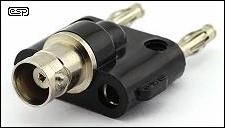
| Good shielding is essential, and you will often be better off using a shielded lead for the input. It needs excellent insulation, but this is rarely an issue with decent coaxial cable. I positioned the ground to each input and the output terminals at 19mm centres so I can use a banana plug to BNC adapter. Since most of my test leads use BNC (including oscilloscope probes which can also be used), this works out well. If you don't have any of these wonderful adapters, you're missing out (the 19mm/ 3/4" spacing is an industry standard). The photo shows what they look like, and they are available from numerous sources (including eBay). They are also available in the opposite configuration, allowing a BNC connector to be joined to dual banana sockets/ binding posts. If you have a mixture of gear using binding posts and BNC connectors, these adapters let you use all of your instrument test leads fitted with BNC connectors. |
The front panel of my prototype (and likely to be the only one) is shown below. It has the 50MΩ and 500MΩ inputs, and a ×1/ ×10 switch, and I included the overload detection circuits. The LED to the left of the 'Zero' pot is the overload indicator, and the one to the right is a power-on indicator. Lest anyone doubt for an instant that a bit of finger contamination couldn't hurt, I had to wash down the entire attenuator section with denatured alcohol (including the 45MΩ and 50MΩ resistors [blue and red respectively in Figure 7]) and leave it to dry for several days before it could measure accurately.
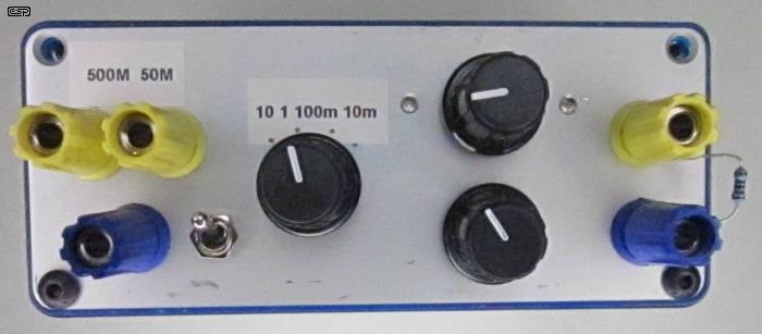
Figure 6 - Front Panel Of Prototype
The internals are shown next. You can't easily see the 'sky-hooked' circuitry, but it's Pin 3 of U1A, both transistor 'diodes' and the 1MΩ input resistor (bottom right of the Veroboard in the photo). The wires to the attenuator are completely self-supporting, and do not touch anything. It's all too easy to see the effect of placing a wire connected to the positive or negative supply onto the insulation of the attenuator wires. A significant voltage (well, a hundred millivolts or so) is easily measured through the insulation!
The toggle switch is for the ×10 gain for the first stage, but is as yet unmarked. The voltage scale was done before I realised that having a total gain of 100 was overkill, and decided that 10mV sensitivity would only ever be used on rare occasions - if at all. It might be changed at a later date, but in the meantime I just have to remember that it's only relevant for the 10mV full scale range. The resistor you see on the output terminals is something I often use, as it gives me an easy place to connect a meter (with clip leads) and/ or my oscilloscope.
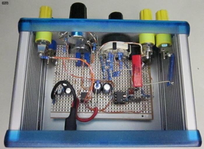
Figure 7 - Interior Of Prototype
While the wiring looks messy, that was essential to prevent high impedance wires from touching anything else inside. The main switched attenuator uses quite a few resistors, and again they must be self-supporting to minimise leakage current. The same applies to the 500MΩ resistor, made using a 450MΩ resistor (blue, right side of the photo) and a 50MΩ resistor (red). While it might appear that the blue resistor is touching the case, it's not - there's about 5mm separating them (I increased the distance after the photo was taken).
The two trimpots for setting the overload detector thresholds are visible just behind the lower 'Set Zero' pot. There really isn't much circuitry on the Veroboard, just the two opamps (the TLC277 is in a socket) and a few resistors. There are also power supply bypass capacitors (100µF and 33µF). The opamps used are not fast, and don't need ceramic bypass caps.
This is without doubt the most sensitive meter I've ever seen - nothing I've come across in 50 years of electronics even comes close. The stability is not wonderful, but that's only at the most sensitive setting (10mV) and it appears worse than it really is because my bench meter has 0.1mV resolution. However, it does not have 50MΩ input impedance, and 500MΩ is well beyond that of any readily available (affordable) laboratory instrument. Yes, you can buy a 'true' electrometer, but you probably won't once you've seen the price.
Note: The supply voltage is 12V, and this must not be exceeded. The TLC277 is rated for up to 16V, with an absolute maximum of 18V between pins 4 and 8. If the supply voltage exceeds the maximum (even briefly), the opamp will almost certainly die.
One thing that a meter like this is ideal for is measuring resistance that's more in the range of insulators. To do this, the meter is really measuring current through a series circuit. If you apply a voltage of (say) 20V to the DUT (device under test) with the meter in series, you might measure 25mV as an example. We know that the meter has a resistance of 50MΩ, so 25mV means a current of 500pA is flowing with an applied voltage of 20V. Since R = V / I ...
R = 20 / 500p = 40GΩ
There's no point subtracting the resistance of the meter, but you can if you wish (the external resistance is 39.95GΩ). Measuring such high resistances makes it almost pointless to subtract the meter's input resistance. No standard multimeter can measure resistance that high, and normally you wouldn't bother. However, if you're working on capacitor ('condenser') microphone circuits, then the ability to verify that the capsule's insulation is up to specifications is important. If you add the 450MΩ resistor to the attenuator, it should be possible to measure up to 1TΩ with 'acceptable' accuracy. In this case 'acceptable' is in quotes simply because such high resistances are subject to errors due to even the smallest amount of contamination, PCB leakage, humidity, etc.
Anywhere else that high circuit resistances exist can be tested in similar manner. The stability (or otherwise) of the high-value resistors used to bias a capacitor microphone can be tested, and it's instructive to see how conductive common phenolic PCB material can be (especially under humid conditions). These measurements will never be precision unless used in a carefully controlled environment.
Electrometers often have additional scales or switching to measure current and resistance, but for a DIY instrument that would be comparatively hard to set up, and would need more switches and gain options for the metering amplifier. It can be done, but it's likely to be easier to just make a couple of simple calculations to determine current and/ or resistance. As you can see from the example above, it's not at all difficult.
If the 500MΩ option is included, this should allow you to determine resistance well into the teraohm range. This is laboratory territory, and most likely not useful to most constructors. Of course, you might be making your own flame ionisation gas chromatograph where this would be handy, but I suspect that this is just a tad unlikely.
This is not something that many people will need, but if you do work with very high impedance circuitry it may well prove itself to be more useful that you imagine. If nothing else, it's a very interesting exercise, and you'll learn about exceptionally low currents (and high resistances) as you progress. I doubt that my unit will be used more than a few times a year, but without it I'd have to cobble some basic circuitry together and make do with that. Now I don't need to, as it's ready for use whenever it's needed.
If nothing else, the circuitry described is educational, even if you don't build one, and it may assist with other ideas you might have. It pretty much goes without saying that a PCB won't be offered, because the number of people wanting/ needing an instrument such as this will be small, and I'd never recoup the cost of the boards. Mine was constructed on Veroboard (other than the high impedance input circuits), and it performs somewhat better than I'd hoped for.
There are no references for this design, because it appears to be unique. Certainly there are similar circuits, including 'solid state' versions of the venerable VTVM (vacuum tube voltmeter). None of those I saw is designed to measure down to 10mV, and most have a voltage divider/ attenuator of no more than 10MΩ. A few JFET designs extend that to 20MΩ. I doubt that there are any 500MΩ versions available as a DIY project.
 Main Index
Projects Index
Main Index
Projects Index