

|
| Elliott Sound Products | Project 204 |
 | Please Note: PCBs will be available for this project depending upon demand. This will be impacted by the current Coronavirus/ COVID-19 pandemic. |
Some of the terminology here will be new to many enthusiasts, but I've tried to keep the explanations as simple as possible. In the end, it doesn't matter if you don't understand the maths behind something like this, and provided you get your connections right it will work regardless. However, understanding the processes involved can only help your overall appreciation of the techniques. There is also scope for some serious respect for the skill of those who developed the frequency shifter in the first place.
There is an introductory article on the topic of feedback and frequency shifting - see Acoustic Feedback In PA Systems (With Special Reference To Frequency Shifting) that should be read before you delve into this project too deeply. The relationships between the microphone and loudspeaker are highly frequency dependent, and are almost always due to room effects (especially reverberation). The complete system (talker, microphone, amplifier, loudspeaker and room) constitute a chaotic system. A small change of just one of the system components can either cause or stop acoustic feedback, and there is no way to predict what will or will not cause the system to become unstable. Simply changing the way the microphone is held in the talker's hand can change the system from stable to unstable, or vice versa.
The principle of frequency shifting (as shown here) relies on the use of analogue multipliers. Earlier systems used complex and expensive SSB (single sideband) radio frequency techniques to achieve the frequency shift, but this method is not sensible in the context of modern electronics. There are two multipliers required, with the two signals into each (audio and low frequency oscillator - LFO) each shifted by 90°. This is called a quadrature signal (for both the incoming audio and the LFO). The oscillator shows a sine and a cosine output - a cosine wave is a sinewave, but shifted by 90°.
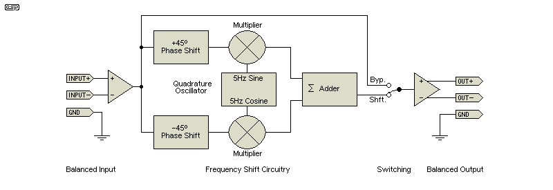
Figure 1 - Frequency Shifter Block Diagram
When the two signals are added together, the result is the original audio, but with the frequency of the input changed by +5Hz. The frequency can be reduced by 5Hz if the inputs to the multipliers are reversed for one or the other signal. Either the audio signal or the oscillator outputs can be switched, but not both. There is no advantage to using a frequency reduction rather than an increase, and either should (at least in theory) give the same results.
When the system is adjusted correctly, there is no trace of the original modulating frequency or the original audio. If the multipliers are incorrectly balanced (having different output levels) or the phase shifts of the incoming audio and/or the 5Hz oscillator outputs are not exactly 90°, there will be amplitude modulation (AM) in the output. If present, amplitude modulation is at 10Hz - double the modulation frequency.
The accuracy of the audio phase shift network is critical to ensure low residual AM, as is the level presented to each multiplier. The second design provides exceptional phase linearity across the audio band, as well as ensuring that the low frequency oscillator has the lowest possible distortion. By using AD633 multipliers, there are only two simple adjustments needed to minimise the residual AM. One is to set the phase shift of the oscillator to exactly 90°, and the other is the balance of the summing circuit.
Because it's not possible to generate a 90° phase shift over a wide range with a single circuit, two phase shift circuits are employed. The difference between the two is maintained at (close to) 90°, so the end result is two signals having a relative phase shift of the required 90°. The overall phase shift is close to 360° across the audio band for circuit #1 (+180° at 20Hz and -180° at 20kHz). This is not audible. Circuit #2 has an overall phase shift of about 660° across the audio band, but this too is inaudible. See below for more info on the phase shift networks.
One multiplier gets a signal that we'll call the 'reference' (one part of the phase shifted incoming audio) and a low frequency (5Hz) sinewave. The resulting output looks like that shown below with a 1kHz sinewave as the audio input. The second multiplier gets the other audio signal (90° out of phase) and the cosine output from the 5Hz oscillator. The outputs of both multipliers are shown.
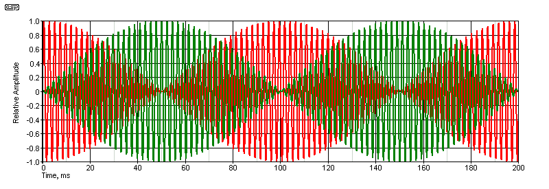
Figure 2 - Multiplication of 5Hz and 440Hz
As noted above, both signal sources in the frequency shifter are in quadrature, meaning the signal is in two parts, with each separated by 90°. The output from each multiplier looks like the above with a sinewave signal input, and the second has each peak coinciding with the null of the first and vice versa. The last stage is to add the two signals together. There's little point showing the output, because it's a sinewave, with the only difference being that it is shifted by 5Hz (giving either 435Hz or 445Hz, depending on the connections to the multipliers).
It's important to understand that this circuit is intended for speech. While many (most?) people will be unaware of the frequency shift with music, some will hear it as a slight discordancy, because the harmonics are slightly detuned. For example, A440 has its second harmonic at 880Hz, but you will hear 445Hz and 885Hz after frequency shifting. The second harmonic has been detuned by -5Hz (it should be 890Hz - 445Hz × 2). The same applies to other harmonics, with the effect getting worse with higher harmonic frequencies.
On speech, this is pretty close to being inaudible even for a trained listener. On a direct A-B comparison you will probably be able to hear the difference, but the relative freedom from feedback is well worth the small frequency errors produced.
Over the years there have been several commercial versions, one comparatively recent (and totally invalid) patent, and a number of systems that use DSP (digital signal processing) to achieve the same (or similar) result. There are units available from China, including at least one that includes a parametric notch filter so that particularly troublesome frequencies can be attenuated. No details are available here. (Predictably, I'm not about to offer free advertising to manufacturers who may or may not be legitimate.) Tunable notch filters (whether manual or automatic) are of very limited use in most venues, because the frequencies that are troublesome vary depending on the mic position, and even that of the talker with respect to the mic. Ambience (reverberation) also changes depending on the number of people in the room, and where they are.
Be warned that the AD663 multipliers are expensive ICs. At the time of writing, they are around AU$20.00 each, and two are needed for the frequency shifter. SMD versions are a little cheaper, not not by enough to warrant designing the PCB to use them. Because I expect that demand for PCBs will be modest, the normal low prices charged for boards won't really apply, so expect them to be a bit more expensive than most other boards (if there's even enough interest to warrant having boards made of course). My guess at this stage is around AU$35.00, but it could turn out to be a little more or less. Considering the cost of a completed unit (even if you could buy one!), it's still comparatively cheap.
It's worth spending a little time discussing analogue multipliers, because they are the basis of many sound effects that became available in the 1970s and 1980s. They can also be used to square a voltage, and are the essential element of VCAs (voltage controlled amplifiers) and were used extensively for VCFs (voltage controlled filters). In early synthesisers, multipliers were often built using transistor arrays.
As you can deduce fairly easily, the basic function is that the (instantaneous) voltage at input 1 is multiplied by the voltage at input 2. With DC, an input of 2V on input 1 and a voltage of 3V at input 2 will result in an output of 6V. This is usually scaled internally, so that the actual output voltage will be 600mV, allowing for comparatively high input voltage without causing the output to clip because of the limited voltage on the supply rails (typically ±15V DC).
Multipliers are divided into three main categories, and while single quadrant multipliers are part of the 'mix', they have never especially useful compared to the others. The most common types are 2-quadrant and 4-quadrant. A 2-quadrant multiplier can only accept positive signals at the 'Y' input, bipolar input signals at the 'X' input, and the output can go negative, while a 4-quadrant multiplier can accept positive or negative voltages on both inputs, and can output positive or negative results. The basics are shown below [ 1 ] ...
| Type | 'X' Input Voltage | 'Y' Input Voltage | Output Voltage |
| 1-Quadrant | Unipolar (+ve only) | Unipolar (+ve only) | Unipolar (+ve only) |
| 2-Quadrant | Bipolar | Unipolar (+ve only) | Bipolar |
| 4-Quadrant | Bipolar | Bipolar | Bipolar |
The primary ingredient for creation of any analogue multiplier is the Gilbert cell, named after its inventor Barrie Gilbert, who created it in 1967 [ 2 ]. It is one of the most important circuits in communication electronics, and multipliers are common in radio frequency systems. It's outside the scope of this article to cover the Gilbert cell in great detail, but there's plenty of information to be found on the Net. Suffice to say that there are countless things that would never have been possible without the multiplier, although most can be done with DSPs (digital signal processors) today.
Before the wide adoption of microcontrollers and computers, many of the functions we take for granted today were performed using analogue techniques. Multiplication, division, squaring, square-roots, amplitude modulation and ring modulators (widely used as a 'special' sound effect, but also used in radio frequency circuits) are all applications for multipliers. They were also common for wattmeters and many other measurement processes.
Modern high quality voltage controlled amplifiers are nothing more than highly linearised analogue multipliers, and they gained great popularity in the days of analogue music synthesisers. Multipliers were also used for VCOs (voltage controlled oscillators) and VCFs (voltage controlled filters). The famous Mini Moog was a good example of a synthesiser that used multipliers, although most were made as discrete circuits back then. Usually, transistor array ICs were used to obtain thermal matching, which is important to prevent drift.
One of the simplest multipliers (as well as one of the most popular) was the CA3080 and its derivatives. This was known as an operational transconductance amplifier (OTA), and was a good example of a 2-quadrant multiplier. The unipolar 'Y' input was used to control the gain of the device, but linearity was rather poor so it had comparatively high distortion. Some of the newer versions (before they were all deemed obsolete) were a little better, but they never approached the performance of the AD633 - one of the few analogue multiplier ICs still available at a reasonably sensible price.
Today, multipliers such as the Analog Devices AD633 are laser trimmed to ensure accurate gain and low DC offset, achieving results that needed trimpots and careful design to achieve with earlier versions. Unfortunately, the functions that used to be the domain of analogue circuits some years ago are now performed routinely with PICs or other microcontrollers, and for a fraction of the cost. However, most can't compete when it comes to frequency response - most analogue multipliers are quite happy with 10MHz (or even 100MHz signal frequencies for some), something that can't be matched by a micro with a only 10-20MHz clock and perhaps only 10 or 12 bits resolution for the ADCs (analogue to digital converters).
Most multipliers are provided with fully differential inputs for the X and Y inputs, and can therefore be used with balanced input signals. Where this isn't required, one of each differential input pair can simply be grounded with no loss of accuracy. Earlier versions (such as the MC1495) required trimpots to null any DC offset, and they lacked the overall accuracy of the AD633 (although they weren't that far behind, which shows extraordinary design prowess for a device launched in the early 1970s).
It's important to understand that analogue multipliers are mostly used open loop (i.e. without feedback). As a result, they can never be as precise as an opamp which is used with feedback (so the circuit behaviour is determined mainly by the feedback network rather than the device itself). When this is considered, the analogue multiplier is a rather remarkable device, with datasheets stating typical errors of 1% or less. These are seriously under-utilised parts, which is most unfortunate because it means they are rather expensive due to the low demand.
The fundamental process of the phase shifter is a 'Hilbert Transform'. The Hilbert transform of a signal x(t) is defined as the transform in which phase angle of all components of the signal is shifted by +/-90°. It's beyond the scope of this article to go into details of the design of a Hilbert transform circuit, as the maths behind it are complex and (fortunately) not necessary for you to build either of the circuits shown. You can look up Hilbert transforms on the Net, and there is copious information available, although it's doubtful that most potential constructors will bother. Like most advanced mathematical formulae, it's not easy to understand unless you have studied such processes in some depth.
The analogue multipliers require both signals to be in quadrature, that is, with a 90° phase shift between two otherwise identical signals, both for the audio and low frequency oscillator. This is easy for the low frequency oscillator (LFO) as only a single frequency is needed. When dealing with audio, it becomes much harder. The only way it can be achieved is to use two phase-shift circuits, with a relative phase offset of 90°. This is a great deal more difficult than it sounds, because there is always a requirement for minimum complexity (and therefore cost), along with performance that it at least 'satisfactory'. What one user considers satisfactory may be very different from another.
Broadband phase shifting in audio is particularly irksome. Unlike RF circuits where the frequency range is only a tiny fraction of the frequency in use, audio is assumed to cover the spectrum from 20Hz to 20kHz - a 1,000:1 frequency ratio. Consequently, there are compromises, otherwise the circuitry becomes unwieldy and overly complex. It's also possible using a DSP (digital signal processor), but that's outside my 'comfort zone', and it would require a very good DSP to handle the full audio range with the complexity of the required digital coefficients. There is also the ever-present problem with any complex digital functions, in that the ICs often have a fairly short production run, so what's available today may well be obsolete by next Thursday.
There are two different approaches used in this article - the simple (but adequate for speech) version originally published by Wireless World in 1973, and the more advanced version designed by Phil Allison some years later. The second version maintains ±2° across the full range, which minimises problems with wideband signals. It's not limited to the voice range, but covers the full audio spectrum.
A 90° phase shift across the full range isn't possible with a single network, so two networks are used, with the difference between them being 90°. The phase shift circuit shown in Figure 5 consists of two modified Wien bridges, with each end driven by appropriately scaled anti-phase signals. The signal voltage at the output of each network remains essentially constant (within 0.25dB), but the phase changes over a range of around ±170°. The phase response is shown below, and the 90° point is indicated. The relative phase shift of this network is positive (+90°).
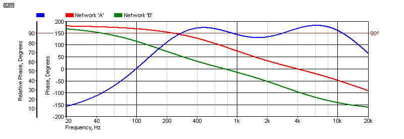
Figure 3 - Phase Response of Updated Wireless World Phase Shifter (Figure 5)
The absolute phase changes by ±170°, while the relative phase (between the two outputs) averages about 90°. At the time the article was published, this was obviously considered 'sufficient', with the bandwidth corresponding to the predominant components of speech, and concentrated in the area where feedback is most likely - between 250Hz and 15kHz. Unfortunately, greater deviations from the optimal 90° means that low frequencies (in particular) will have audible amplitude modulation. Ideally, the frequency response of the WW circuit should have been limited (150Hz to 15kHz) with high and low pass filters, but these were not included. The Wien bridge circuits don't lend themselves to adding extra networks to improve the response, so the end result is a compromise. With a deviation of up to 8.5° at 6kHz, the amount of AM will be around 7.4%. With only 80° phase shift at 250Hz, AM is 7.7%, which is definitely audible - at least with a sustained note.
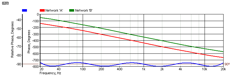
Figure 4 - Phase Response of Phil Allison's Phase Shifter (Figure 6)
Rather than modified Wien bridge networks, Phil Allison's circuit uses the phase shift created by two complementary all-pass filter networks. These are designed to provide the phase shifts shown in the red and green traces. The difference between the two is close to 90° from 20Hz to 20kHz, with only a small error. The relative phase shift of this network is negative (-90%deg;).
The deviation is limited to (roughly) ±2°, so AM is minimised across the entire audio range. This won't improve the ability of the circuit to minimise feedback, but it does eliminate the audible artifacts. There is no requirement to limit the bandwidth, because the phase shift network is accurate across the full bandwidth. With a 2° error, the AM level will be around 1.7%.
In this project article, there are two different versions of the frequency shifter. The first is based on the Wireless World original, but updated to use AD633 multipliers, and re-configured so that the circuitry is a bit more up-to-date. It's performance is nowhere near as good as the second version, but for most speech only applications it will probably be fine. Because the phase shift network used for the signal path is so simple, there will be some residual amplitude modulation of the output, and this isn't helped by the distortion generated in the quadrature oscillator.
However, it's certainly no worse than the original Wireless World unit, and because of better opamps it will have significantly greater signal to noise ratio. The most compelling reason to use it is cost and complexity. The version designed by Phil Allison has dramatically better performance in all respects, but some will see it as being too complex to assemble on Veroboard or similar. Others may simply not need the level of performance that can be achieved, and I leave it to the reader to decide.
| Network 'A' | Network 'B' | |
| Upper | 3.70 kHz (4.0 kHz) | 723.4 Hz (720 Hz) |
| Lower | 3.93 kHz (4.0 kHz) | 718.8 Hz (720 Hz) |
Ideally, the upper and lower networks would have identical centre frequencies as shown in brackets, but that requires very odd values and only offers a marginal improvement. The values shown are a reasonable compromise. The effective frequency range is from 223Hz to 12kHz, with a phase deviation of just under ±6°. This is (just) sufficient for speech, but it's not at all suitable for music.
The phase shift network's impedance has been reduced by an order of magnitude over the original (a factor of 10), which minimises noise and presents a respectable impedance to the multipliers. Capacitors marked with a star (*) should be selected to within ±2% or better to maintain the proper phase relationships. Because of the relatively low resistor values, an NE5532 is suggested for U1, because it can drive the network without distortion. The maximum suggested input level is 1.5V RMS, because higher levels will cause U1B to clip (it operates with a gain of 2.8 or just under 8dB). U2 should also be an NE5532 to ensure the output stage can drive low impedance loads without overload.
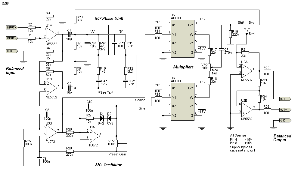
Figure 5 - Updated Wireless World 5Hz Frequency Shifter
The low frequency oscillator (5Hz) is critical in a number of respects. The distortion must be as low as possible, otherwise the frequency shifted output will have amplitude modulation. The sine and cosine outputs also need to be the same voltage, or it may not be possible to set the modulation null to obtain minimum AM. Finally, and most importantly, it must start reliably and run at a constant amplitude. Common quadrature oscillators (as used by Hartley-Jones in the original Wireless World article) can only start reliably if one is willing to accept relatively high distortion (>1%). If adjusted for minimum distortion, they may not start at all, or can take some time (from several seconds to a minute or more) to reach the final output level. This is unlikely to be unacceptable.
The quadrature oscillator shown in Figure 1 is very similar to that originally used in the WW design, but it has been changed to improve performance. VR2 is used to set the gain of the two opamp stages so the circuit oscillates reliably, but still has acceptable distortion. With the values shown, the frequency is 5.3Hz. If you prefer a slightly smaller frequency shift change the two 300k resistors to 330k, which gives a frequency shift of 4.8Hz. It's important to ensure that the gain is sufficient to provide reliable oscillation, but not so high that the distortion is greater than 1%. It can be done, and tests indicate that less than 1% THD is achievable fairly easily. Measurements of distortion at around 5Hz are probably outside the abilities of most distortion analysers, so some guesswork may be needed.
This circuit will have some residual amplitude modulation at double the LF oscillator frequency, but provided it's less than 10% most listeners will not hear it with speech. It will be audible with sinewave testing, but that's not how the circuit is used and it's unlikely to cause issues. If better performance is required, the second circuit is easily capable of maintaining residual AM to below 1%. R9 is shown as 4.3k, but if unavailable you can use 3.9k if you are willing to accept slightly more amplitude modulation at around 400Hz.
If you have (or can get) 4k3 resistors, that matches the (scaled) original perfectly. As shown in Figure 3, phase shift between around 200Hz and 15kHz is within ±10°, and the original frequency range has been retained. It would be tempting to try to improve the network, but Circuit #2 has far better performance than you'll ever get with variations on the above.
This is Phil Allison's design, which while more complex, will give far better performance. The phase shift network and oscillator both have superior specs over the first version, and this is the circuit to build if you need a frequency shifter in your PA setup. Phil put a great deal of effort into this design, and it's worth it.
The phase shift network uses U2-U5, with one half of each used in the first section (U2A-U5A, and the other in the second section (U2A-U5B). Each opamp is part of an all-pass filter (phase shift network), and four are needed in each 'leg' to get the response shown in Figure 6. The frequencies of each network are defined as that frequency where the phase shift is 90°. Each is shown below, based on the formula ...
fo = 1 / ( 2π × R × C ) (Where R is the series resistance, and C is the capacitance to ground)
| U2 | U3 | U4 | U5 | |
| Upper (UxB) | 10.8 Hz | 132.6 Hz | 1.06 kHz | 8.84 kHz |
| Lower (UxA) | 45.2 Hz | 376 Hz | 3.03 kHz | 37.0 kHz |
The spacing between the frequencies is not easy to calculate, and will always be a compromise. Unfortunately, the original design data are no longer available so I can't include the details here. One thing you can be sure of is that it involves fairly complex equations, and these aren't needed when all the information is provided for you. I usually provide as much information as possible, but as regular readers will know, I generally steer clear of very complex equations because I know that almost no-one will try to use them.
Each frequency is based on the values in the RC network connected to the non-inverting input of the opamp. The frequencies are staggered in such a way as to maintain 90° phase difference between the outputs of U5B and U5A across the audio band. As shown, it's about as good as it's possible to get, even with even greater complexity. You can also see that odd value resistors have been avoided, and resistors in series are used to obtain values that would be otherwise hard (or impossible) to obtain.
The capacitors marked with a star (*) should be measured to get the values within 2% or better. Standard tolerance is ±10%, and this will cause unacceptable deviations to the phase networks if they aren't selected. Many multimeters have a 'capacitor test' function which should be be quite alright if they have a resolution of no more than 10pF. Make sure that you use very short test leads so lead capacitance doesn't cause errors. An alternative is to use 1% (or 2.5%) tolerance polystyrene capacitors, which are available from a number of suppliers in both 1nF and 10nF. These are one of the most stable caps you can get, but polystyrene is 'thermo-phobic', so excess heat while soldering can damage them. Expect to pay around AU$3-4 each for 1% caps.
Another alternative is polypropylene capacitors, which are also available in 1% tolerance. These are more stable than Mylar/ polyester, but are slightly larger. For the values needed, they are available with a standard lead pitch of 5mm, and are a less expensive option than polystyrene.
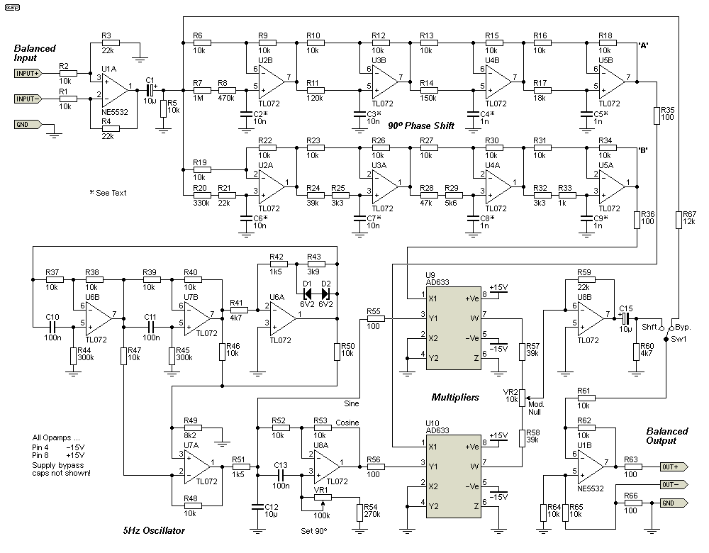
Figure 6 - Improved 5Hz Frequency Shifter
The improved version uses a more complex phase shift circuit, which ensures excellent response over the full frequency range. The phase shift is as close to 90° throughout the audio band as is reasonably possible, and this reduces the amplitude modulation, particularly at low and high frequencies, where the original is well out of specification, with phase shift falling to as low as 60° at the frequency extremes. The balanced input is retained, but in order to save an extra opamp, the output uses an earth balancing scheme. This means that the output is still balanced, but it doesn't have the signal on both leads. This arrangement works just as well as a 'true' balanced output stage as far as the following mixer is concerned.
As shown in Figure 4, the deviation of phase shift is inconsequential (±2°) over the full range from 20Hz to 20kHz. The low deviation from the ideal 90° ensures minimal AM at any frequency within the audio range. While the network could be simplified, it's not worthwhile, as it's not expensive and it uses relatively cheap parts throughout. Coupled with an oscillator having lower distortion and adjustable phase to ensure that the 5Hz modulation has exactly 90° phase shift, the performance can't be beaten by any commercial frequency shifter ever offered.
The oscillator is also significantly upgraded compared to Circuit #1. Some may recognise it as using the same topology as Project 86 (miniature audio oscillator). The P86 PCB can be used (with a few simple modifications) so that the oscillator doesn't need to be built on Veroboard (assuming no PCB of course). Distortion is well below 0.5% (0.2% is typical), and the phase relationship is carefully adjusted using VR2 so that it's exactly 90°.
| Specifications (Circuit #2) | |
| Shift | 4.8 Hz upwards |
| Frequency range | 22Hz to 24kHz ±0.5dB |
| Input Impedance | 10kΩ unbalanced, 20kΩ balanced. |
| Output Impedance | 100Ω, minimum load 600Ω |
| Nominal input | 1V RMS, 11dB headroom (3.5V RMS max.) |
| Noise | -82dBV, unweighted (20Hz to 20kHz) |
| THD | 0.07% at 1kHz and 2.5V RMS (all 2nd harmonic) |
| 10Hz modulation | 2% maximum (any frequency) |
| 5Hz residual | 3mV RMS |
The specifications are exemplary, and are actually far better than required for speech. It's very doubtful that any commercial version (if any are still available) would come close. This is due to the high accuracy of the phase shift network and low oscillator distortion, along with careful design of the remainder of the circuit.
The recommended supply is Project 05, as it is very quiet, with low ripple and wideband noise. No specification for power supply rejection ratio (PSRR) is provided in the AD633 datasheet, and only the allowable supply voltages (between ±8V to ±18V) and typical supply current (4-6mA) are provided. The recommended supply voltage is ±15V, and that's what the circuit was designed to use. Not stating the PSRR is often an implied indication that it's not particularly good (the earlier and now obsolete MC1495 claimed 40dB, which is less than almost any opamp known).
Using a power supply with low noise ensures that supply noise won't be intrusive. It would be possible to include the supply on the PCB (if there's enough interest to make it worthwhile), but that increases the PCB size, making it more expensive to produce. This isn't a project that's expected to have wide appeal, so it's important to keep the cost as reasonable as possible.
The Project 05-Mini board can also be used, but I'd recommend adding a 'post-filter', using 10Ω resistors in series with each output, with at least 470µF caps after the resistors to ground. This makes is less appealing overall, but it does reduce the total cost a little.
The setup processes are similar for both circuits, except that Circuit #1 requires that the oscillator gain be adjusted, and Circuit #2 requires an oscillator phase adjustment. For Circuit #1, adjust the oscillator gain control (VR2) to ensure that the oscillator starts reliably and quickly after power is applied. If possible, check that the distortion is less than 1%, as low distortion helps to minimise amplitude modulation of the output signal.
When you are happy with the oscillator, apply a 1V RMS signal at around 1kHz and adjust VR1 for minimum amplitude modulation. Ideally, you will use an oscilloscope to do this, because it's not always easy to detect the minimum AM if you can only listen to it. VR1 will normally be set very close to halfway. Check that the residual AM is within 10% at a few different frequencies, such as at 300Hz and 3kHz. It may be necessary to tweak VR1 slightly to get an acceptable result across the audio band.
For Circuit #2, the two trimpots (VR1 and VR2) are somewhat interdependent. Again, VR1 should be close to the centre position, and VR2 is adjusted for minimum AM. After adjusting VR2, try varying VR1 a little to reduce the AM level. Work between the two trimpots until the output signal has almost zero AM. There is no need to re-adjust either trimpot for different frequencies, because the phase relationship is almost perfect across the entire audio band.
In use, adjust the mic levels until the system is on the verge of feedback, then switch in the frequency shifter with Sw1. All feedback 'artifacts' should disappear. If you turn up the gain further, the onset of feedback is indicated by a 'warbling' sound that is a clear indication that you've hit the gain limit of the system. The amount of additional gain you can use depends on the environment. Frequency shifting is most effective in reverberant rooms, where the feedback is due to reflected signals arriving back at the mic diaphragm. It's far less useful outdoors or in non-reverberant spaces, and will not generally improve the gain-feedback ratio. It also has minimal effect when the problem is caused by the mic being too close to the speaker, where it picks up direct sound.
In all cases, the talker needs to use the mic correctly. Avoid multiple 'open' (switched on) microphones wherever possible - only the mic being used at the time should be open, and all others turned off. Where possible, do not have microphones facing the loudspeaker(s), as this allows direct pickup of the amplified signal, and preventing feedback will be virtually impossible at anything more than very low mic gain settings.
The frequency shifter is not a panacea, and it cannot be expected to perform miracles (even if used in a church or any other house of worship  ). However, these are often very difficult environments because of long reverberation times and many reflective surfaces, in particular older churches or cathedrals where there is usually no attempt at controlling the sound field.
1 Gilbert Cells - https://user.eng.umd.edu/~neil/EE408D_02/Design_Ex/Mixer/mixer.html
2 Gilbert Cell - Wikipedia
3 MT-079 TUTORIAL Analog Multipliers - (Analog Devices)
4 ADI Multiplier Applications Guide - Analog Devices (1978)
5 FREQUENCY SHIFTING FOR ACOUSTIC HOWLING SUPPRESSION - Edgar Berdahl, Dan Harris
6 Frequency Shifter for 'Howl' Suppression, M Hartley-Jones, Wireless World, July 1973 p317.
7 Suppression of acoustic feedback by frequency shifting - Kristoffer Emil Mørch Amundsen
8 An AF All pass Quadrature Networks Practical Approach - Old Technique Revised (Dipl. Ing . Tasiae Sinisa - Tasa YU1LM/QRP) PDF
9 Acoustic Feedback & Frequency Shifting - ESP Website
10 Frequency Shifter, Electronics Australia Magazine, 1997 (Phil Allison)
 Main Index
 Projects Index