
|
|
| Elliott Sound Products | Project 202 |
Piezo transducers are common in a range of different areas. They can be used as pickups for various musical instruments, such as acoustic guitars, violins, cellos, double-bass (aka upright bass), ukuleles and mandolins (etc.), and also as accelerometers. In most cases, the input impedance needs to be somewhere between 'high' (1MΩ or so) to exceptionally high (greater than 100MΩ). Almost without exception, this means a FET input, either JFET or FET input opamp. While bipolar input opamps can be used, there will be a significant noise penalty. However, there is an exception to the 'high impedance' rule that's covered later (charge amplifier)
For reasons that escape me, I've not described a piezo preamp before this, even though I have used piezo transducers in a number of projects developed for customers. I've also experimented with piezo transducers. The basic principles are discussed in the article High Impedance Input Stages / Project 161. The general principles are discussed in some detail, but it can't be considered a 'true' project for several reasons.
For starters, the final circuit (shown in Figure 10 of the referenced article) requires the use of a 1GΩ resistor, and these are not easy to get and are expensive. The circuits shown in the article/ project are intended more for a specialised bench amplifier, and aren't really suitable for musical instrument pickups. The circuit is simplified considerably for musical instruments, because response below 40Hz isn't necessary (the lowest note on a traditionally tuned double bass is E1 - 41Hz). Some players tune for C1 (32Hz), but that's still easily accommodated with the circuits shown below.
The three circuits are shown using a 9V battery and an OPA2134 (or NJM2068) opamp. While the OPA2134 is a fairly expensive opamp, they have much lower noise than the common-or-garden TL072. A single 9V battery is not advised for a TL072 because it is not designed for operation at less than 10V. Be aware that the OPA2134 draws roughly double the supply current of a TL072, so battery life will be reduced. 9V alkaline batteries have a typical capacity of around 580mA/h, so with a load of ~10mA it should provide over 50 hours operation (including the LED). The OPA2134 (or the single OPA134) has an input impedance of 10TΩ - and that is not a misprint. Even the TL071/2 has an input impedance of 1TΩ, with typical bipolar opamps only providing around 300MΩ or so open loop. This is increased when feedback is applied.
While it's generally assumed that a pickup should respond to the lowest fundamental (82Hz for guitar, 41Hz for 'traditional' [four string] bass), a characteristic of most plucked or struck strings is that the second harmonic is usually dominant (depending on the striking/ plucking position and/ or style). If the fundamental is boosted, many players will find the sound to have excessive bass, so it's not always wise to ensure that you have flat response down to the fundamental frequency. The circuits and descriptions below assume flat response to the fundamental frequency, but this can be changed by changing the value of the input resistor. This will work for the second and third circuits, but is a bit more involved for Figure 1 because its input impedance is much higher than 'normal'.
Unfortunately, many piezo pickups have little or no data available on the piezo itself. Trying to discover the capacitance of some is almost impossible, unless you can find a forum post where someone has measured it. The other alternative is to measure it yourself, but if it has an attached cable, you're also measuring cable capacitance, and separating the two may not be possible. It would be helpful if this information were made available, but some manufacturers seem to want to keep as much as they can a secret. This isn't helpful for people who want to DIY.
A piezo transducer is effectively a vibration-sensitive voltage source in series with a small capacitor. The capacitance varies, mainly depending on the physical size of the piezo element. Large piezo transducers have higher capacitance and vice versa. One thing you can be sure of is that the effective capacitance may be no more than 12nF (12,000pF), with many being a great deal less. Some piezo accelerometers can have as little as 200pF capacitance, meaning that the preamp input impedance must be at least 20MΩ to get a -3dB frequency of 40Hz. If you aim for a higher impedance, the circuit is more flexible, and can handle a wide range of different pickups. A piezo taken from a 'sounder' (Sonalert or similar beeper) will usually have more capacitance than dedicated pickups, but there's no guarantee of fidelity.
There are three options described below. The first two are more-or-less conventional, but the third circuit is somewhat different. Charge amplifiers not uncommon in scientific and industrial applications, but are rarely seen for audio pickups. This is a real shame, because this topology has some unique advantages over the more traditional approaches. These are described in the third section of this article. You can choose the circuit that best suits your application, but make sure that you understand the limitations of each type.
Each of the circuits show a volume control, but if you don't need that it can be omitted. Just replace the pot with a resistor (anything from 10k to 100k is fine). I used a 10k pot to ensure there will be no problems driving most cables to a DI box, amplifier or a 'wireless' belt-pack. The 100 ohm resistor in each output circuit ensures that the opamp's stability isn't compromised by lead capacitance. Cable capacitance can cause opamps to oscillate.
In case anyone is wondering (or even if you're not), the 12V zeners prevent some conceivable inputs from 'boosting' the supply rail to possibly damaging voltages. While it's highly unlikely, they are cheap insurance if a high-level signal is applied when the battery switch is off.
The circuit diagram for the first option is shown below. The high impedance input is created using a bootstrap circuit, which eliminates the requirement for very high resistances. While it might appear that using a discrete JFET would provide more options (including lower supply voltages), the range of suitable devices keeps shrinking all the time. Once ubiquitous devices are now obsolete, and finding substitute JFETs is becoming a real challenge. While there are a few that should remain available for some time, they are not intended (and are less than ideal) for amplification, and the parameter spread of JFETs means that the bias circuit usually needs to be adjustable. This is inconvenient, and makes the circuit harder to build and set up. Small-signal MOSFETs (such as the 2N7000) are too noisy and should be avoided.

Figure 1 - Bootstrapped Piezo Preamp
Using the bootstrap circuit does have a (potentially serious) disadvantage, in that there can be an unintentional boost at some (usually very low) frequency. This is reduced by making the bootstrap capacitor much larger than necessary, which keeps the boost frequency below 1-2Hz at most. The second line of defence is C1, which ensures that the capacitance 'seen' by the circuit can never exceed 4.7nF. The third defence is created by C3 and R5-R6, which are selected for a -3dB frequency of 31Hz. If you need good response down to 30Hz, simply increase the value of C3. 330nF brings the -3dB frequency down to 21Hz, and there is less than 2dB loss at 30Hz. A larger cap will reduce this further.
In the circuit shown, the gain is only two, set by R7 and R8. If more gain is needed, simply reduce the value of R8 and/ or increase the value of R7. If R7 stays at 10k and R8 is reduced to 1k, the gain is eleven (20.8dB). The gain of the input stage cannot be increased, because the bootstrap circuit relies on unity gain. It is possible, but causes extra complications that mean that performance suffers.
There are several examples of piezo preamps on the Net, and a few use bootstrapping. Very few of those consider the likelihood of creating a high-Q filter with a large low-frequency peak with some pickups. It's a very real problem, and if not addressed as described here, you can easily get a peak of over 15dB at some (low) frequency. This will most commonly be below 10Hz (around 2-5Hz is likely with typical pickup capacitance), and it's not seen because most people don't run tests down to very low frequencies. If the resonance peak is stimulated by moving the instrument or just applying pressure on parts of the body, the peak can be damaging to speaker systems if it's not addressed.
The bootstrap circuit consists of R1, R2, R3 and C1. The signal from the output is coupled back to the junction of R1, R2, R3 and C2, with the latter in series with R4. That ensures that the voltage across R3 is only about 7mV, so the signal current through it is minimised. There will be about 7nA through R3 with an input of 1V, so the apparent resistance of R3 is 140MΩ (1V / 7nA). This simple 'trick' allows us to use a much lower value for R3, which reduces noise. However, it also creates a filter circuit (similar to a multiple-feedback high-pass filter), but the operating conditions are uncontrolled. C2 and R4 provide just enough control to prevent excessive gain at very low frequencies that could lead to damped oscillation.
With the values shown, the input impedance is about 140MΩ and response is flat to below 10Hz. Some pickups may create a small response peak (depending on capacitance), but it will always be below 2dB (and less than 2Hz) for any capacitance between 150pF and 12nF. The worst case is with high capacitance (10nF or more), but the C2/ R5-R6 filter removes it (almost) completely. The peak is at just over 1Hz, and is attenuated by over 20dB by the C3/ R5-R6 filter. The combination of different techniques is used to ensure that the circuit is unconditionally stable with any likely source capacitance.
The LED must be a high brightness type (the higher the better), and it may be possible to reduce the current by increasing the value of R10. As more current is drawn by the LED, battery life is reduced. With ~1.6mA or so with a 10k resistor, the battery will be discharged faster than without the LED, but the risk of leaving the preamp turned on is minimised. The two should balance out, as you'll know that the power is still on by the LED shining brightly. If you don't need the preamp to be portable, it can be powered from ±5-15V from a suitable power supply.
Piezo pickups are always tricky. They don't like long leads, as that creates a capacitive voltage divider, reducing the level. Contrary to what you may imagine, it does not normally affect the frequency response. For example, if your pickup has a capacitance of 10nF and the lead has the same, the output is reduced by 6dB, but response remains flat when provided to a circuit with a very high input impedance.
One major issue can be the triboelectric effect [ 1 ] - an electrical signal developed in the cable itself due to movement. Anyone who has heard the noise from a guitar lead (without the guitar) will have noticed noise when the cable is moved around. Use of a good quality (and ideally as short as possible) lead will reduce triboelectric noise. You may need to try a number of different leads to find one that makes the least noise.
Some piezo pickups and contact mics have considerable capacitance (12nF or more), and these can work with a lower input impedance. Because the pickup has high capacitance, it effectively shorts out high frequency noise, and a bipolar input opamp may be the better choice [ 2 ]. This isn't something I've tried, but I do know that the technique works, as I have used it but with JFET input opamps. It's very common with capacitor ('condenser') microphones, where the (considerable) noise from a 1GΩ resistor is effectively shorted out by the mic's capacitance. These microphones are known for being low noise, despite the very high resistances used.
For high capacitance piezo transducers, there is no appreciable difference between a capacitor/ 'condenser' mic and the piezo, because the piezo element also has capacitance which shorts out much of the resistor and opamp input noise. The following circuit is suitable for larger piezo elements, which have more capacitance due to their physical size. With a capacitance of 10nF and a 1MΩ input resistor, the resistor and opamp noise is rolled off above 16Hz. Be aware that the input current for the opamp passes through R3, and there is a resulting voltage drop. For example, if the opamp draws 1µA input current, that causes a voltage of 1V DC to appear across R3.
The suggested NJM2068 uses PNP input transistors, so the DC voltage on the output (pin 1) will be higher than the voltage across C2 (nominally 4.5V DC with a 9V supply). If you are struggling with high level inputs, this may cause premature clipping of positive peaks. If that's the case, reduce R2 to 8.2k, which will reduce the reference voltage and should bring the DC level from U1A closer to 4.5 volts. If you use an opamp with NPN input transistors, you'd reduce the value of R1 instead, as the DC output will be lower than expected. You can also use a JFET input opamp - that's what I used for my second test preamp (described below).
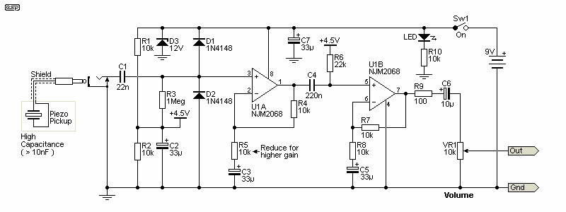
Figure 2 - High Capacitance Piezo Preamp
I've used the same basic layout (using a dual opamp), and this version doesn't use bootstrapping. Input impedance is 1MΩ - the value of R3. The suggested opamp is the NJM2068, which has the same noise level as an NE5534. It can be used as a pair of single stages, with both halves of the opamp used as preamps. This will be useful for stereo pickups. If you use the preamp in stereo, there's only one gain stage, and the output network (R10, C5 and R11) is duplicated for both halves of the opamp. As shown, each stage has a gain of two (6dB) giving an overall gain of four (12dB). If more gain is needed, the input opamp should have its gain increased, as that minimises noise. If you use a gain of more than eleven for the first stage (R5 will be 1k), the total gain is just under 27dB. Higher gain is not recommended, as the input impedance of the opamp will be reduced.
The 4.5V reverence supply is simply a ½ voltage, derived by R1 and R2, and bypassed by C2. The voltage divider can be used for both opamp inputs because there is minimal current drawn, so there is no interaction.
The final configuration is a charge amplifier [ 3 ]. These are a special case, and usually rely on a very high value resistor, and will only work properly with a FET input opamp. The most common use is within high-grade (and therefore expensive) accelerometers, but there's no reason not to use them with a normal input jack and an external piezo transducer. The gain is determined by the capacitance of the piezo and the charge amplifier's capacitance (Cf). Cf is in parallel with the bias resistor (Rf) which must exist or the circuit has no DC feedback and will not work. The combination of Rf and Cf determine the low frequency -3dB point with the standard formula ...
f = 1 / ( 2π × Cf × Rf )
The circuit might look like an integrator, and that's quite true - it is. However, the input signal is provided through the piezo's capacitance (which acts as a differentiator), and the two balance out. If Cf is made larger, the gain falls and vice versa. Cf is always in parallel with Rf, and the low frequency -3dB point is 16Hz. If Cf is 5nF, gain is two and the -3dB frequency is raised to 32Hz. It's apparent that if you wanted high gain and good low frequency response, Rf becomes an inconveniently high value.
When you see descriptions of charge amplifiers, the characteristics are often described using the charge (Q) developed by the piezo, usually in Coulombs (amperes/ second). In a few cases you may see the claim that the gain of a charge amplifier depends only on the feedback capacitor (Cf) and is not affected by the capacitance of the source or the connecting cable. This is not true! The gain is set by the ratio of piezo capacitance and feedback capacitance. Because the input impedance of the charge amp is close to zero, cable capacitance has no effect on gain or frequency response. It should be apparent that a capacitor across a near short-circuit can have no effect. Not usually mentioned is the fact that cable capacitance increases opamp noise, and if high enough, it will cause premature high frequency rolloff.
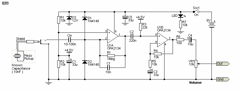
Figure 3 - High Capacitance Piezo Charge Amplifier
For home construction, this isn't a technique I'd recommend for low capacitance piezos, because the resistor (Rf) has to be a very high value. For most pickups, if you can't find the capacitance value in the specifications, you can measure it (if you have a capacitance meter), or just start with 10nF. Changes can be made as required when you run tests. If you need gain, in theory you simply make Cf smaller than the capacitance of your transducer. However, the low frequency cutoff is determined by Cf and Rf, so as Cf is reduced in value, Rf must be increased by the same amount. This is usually impractical unless you have very high resistor values available, but unlike circuits with very high input impedance, the circuit is fairly tolerant of minor leakage currents. The circuit shown above assumes unity gain, and a piezo element with 10nF capacitance. Anything less requires that Rf has to be over 1MΩ, but of course that depends on the low frequency limit you need. The second stage is used to obtain the gain required.
Note that the input socket does not have a shorting switch, as that would boost the gain of U1A, potentially leading to excessive noise. The input capacitor (Cin) should be chosen based on the capacitance of your pickup, and will ideally be around ten times the capacitance. So, for a 1nF piezo, Cin should be 10nF. The circuit is inverting, and has a very low input impedance, so protection diodes are not strictly necessary, although they are advised in hostile environments. The input voltage at U1A (pin 2) is (close to) zero, and triboelectric effects are almost entirely eliminated. Noise from Rf is attenuated at 6dB/ octave above the -3dB frequency, but opamp input voltage noise is amplified by two (6dB). This is expected for any inverting opamp stage.
For the tests I ran on this configuration, I used a TL072, and even when followed by a ×100 preamp (40dB) it was close to dead quiet (although the piezo I used for testing has higher capacitance than most). Based on the limited number of tests I could run (I don't have any dedicated piezo pickups I could use), the circuit should be fine with pickups down to around 500pF (Rf should be 10MΩ and Cf will typically be around 470pF). That sets the -3dB frequency to 34Hz. See the 'Test Circuits' section below for more info.
For instrumentation, you may need response down to a few Hz or less, but if used for musical instruments this is relaxed. If the piezo and feedback cap (Cf) are both 10nF (Cin should be 100nF) and Rf is 1MΩ the -3dB frequency is 16Hz, so good response is possible with piezo elements down to perhaps 1nF (requiring Rf to be ~4MΩ for response down to 40Hz. This isn't difficult to achieve with off-the-shelf parts, and 'special' construction techniques are not required. Cable capacitance does not affect response or gain, but if it's too high the circuit will be noisy.
This is not a technique that you are likely to come across for audio circuits, although it does pop up in a few places. Mostly, it is confined to test and measurement or industrial/ scientific applications. This should be sufficient reason to consider using it, because audio circuits are usually far less demanding than those for measurement/ industrial/ scientific systems. In particular, the freedom from cable noise alone is good enough reason to consider this approach. Because the input is low impedance, hum pickup (50/ 60Hz) is greatly reduced - to the point where it's almost eliminated!
The drawing below shows a charge amplifier with basic tone controls. The same arrangement can be used for the circuits in Figure 2 and 3, but the Figure 1 version doesn't have a 'dedicated' 4.5V split supply. It can be added using the two 10k resistors and bypass cap (R1, R2, R3), and the non-inverting of U1B can be referenced to it in the same way (rather than the two separate resistors shown). The tone controls are just a basic Baxandall circuit, providing bass and treble. Because the second half of the opamp is used for the tone controls, there is no longer a gain stage.

Figure 4 - Piezo Charge Amplifier With Tone Controls
There's nothing special about the tone controls, but the impedance is lower than usual to minimise noise. Maximum boost and cut has been limited to ~10dB, as any more than that is more likely to cause feedback than do anything useful. The values around the tone controls can be changed to modify the response to suit you needs.
As shown, the treble control operates from a much lower frequency than is typical. I expect you'll either love it or hate it, but it's very easy to change. To raise the frequency, simply replace C4 with a lower value. For example if you just want to add (or remove) the very top-end of the frequency range, you could use as little as 2.2nF. With 15nF, treble boost is +3dB at 700Hz, rising to 5kHz with 2.2nF (maximum boost). With 6.8nF as shown, +3dB is at ~1.6kHz.
With these circuits, tests are essential. While all circuits simulate perfectly, that doesn't necessarily mean that they will behave themselves in real life, and it's especially difficult to assess circuit noise. The two circuits tested are nominally unity gain, and the piezo was liberated from a 'Sonalert' type electronic beeper. I measured the capacitance at 32nF, somewhat higher than I expected. The left circuit is a charge amplifier, and the one on the right is a unity gain version of Figure 2. I used a TL072 opamp, with one section for the charge amp and the other for the 'High-Z' preamp. The opamp was powered with a single 12V power supply.
The charge amplifier uses the circuit shown around U1A from Figure 3. The output is via a 33µF electro and a 100Ω resistor (top left). The high impedance preamp is the same as that shown in Figure 2, with only the circuitry around U1A, but without the protection diodes. It uses the same output cap and resistor as the charge amp (top right). The two circuits share the same bias network. Without the piezo connected the noise from both is fairly low, but the high-Z amp picks up hum very easily. The test amps are not shielded, and were tested in the form shown in the photo.
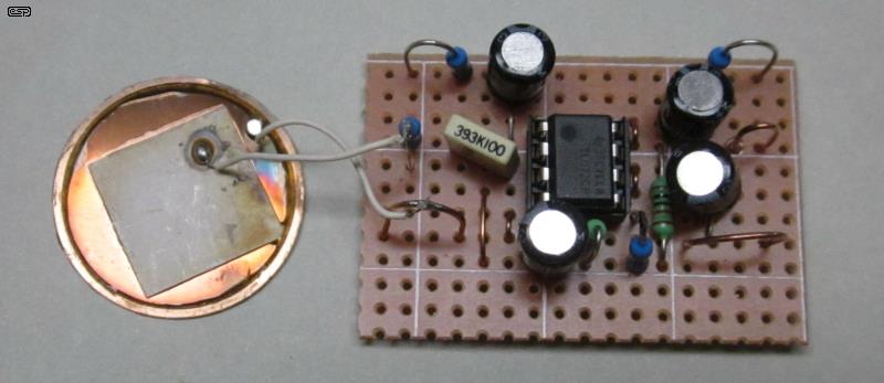
Figure 5 - Piezo Disc & Test Preamps
On the left side of the board is the charge amplifier (Fig 3). I used a 39nF feedback cap as I didn't have a 33nF cap to hand at the time (39nF causes a slight gain reduction). The feedback resistor is 1MΩ, and the same is used as the input resistor for the high input impedance version. Circuit noise was very low for both, but (very usefully!) the charge amp had virtually zero hum. This is a real bonus, as it was almost impossible to eliminate hum with the high impedance version. Hiss was very low with both circuits (I used a calibrated low-noise preamp between the circuits shown and my bench power amp).
The piezo element has its brass backing plate connected to earth (ground), but even with the very short leads seen in the photo, the 'High-Z' version produced 50Hz hum no matter how far it was from any hum source. On that basis alone, the charge amplifier is a clear winner. This was expected, but it's something you cannot be certain of until a test is performed.
Given the much higher than expected capacitance of the piezo, even with only 1MΩ as the feedback resistor, the charge amplifier circuit has good response to 5Hz, which is much less than necessary for musical instruments, but is useful for test and measurement applications. Even with a gain of seven (Cf = 4.7nF), the circuit will have good response to 33Hz (-3dB), while retaining Rf at 1MΩ. I resisted the temptation to use 10MΩ (or 1GΩ) resistors, and they aren't necessary with a piezo having so much capacitance. To give you an idea of how low the response can extend, with a 1GΩ feedback resistor and 33nF integrating capacitor, the -3dB frequency is under 5mHz (0.005Hz, corresponding to a periodic time of 200 seconds!).
My test involved simply wiping the piezo lightly with just the corner of a facial tissue (not scrunched up!), while the piezo was suspended by its leads. Even with my bench amplifier turned up to near maximum (with a x100 preamp between the piezo preamp and the power amp), noise (hiss) was only just audible. Tapping the piezo - even very lightly - was loud. If the piezo was allowed to rest on my workbench, it resulted in feedback. I measured the output of the piezo with very light touches at around 2mV peak. Even the most gentle tapping gave a far higher output level, and over 1V peak is easy to achieve.
Having seen for myself what a ceramic (aka 'crystal') cartridge can do to vinyl (in the late 1960s), this is not something I would ever recommend. However, for 78 RPM discs they are probably ideal, as the material is very hard and won't be damaged. There's also no requirement for high fidelity, because you won't get it from 99% of 78s. These cartridges have high tracking force - where magnetic cartridges need a couple of grams, ceramic cartridges need around 10 grams (typical). Back in 1971, circuitry was described in Wireless World magazine [ 5 ]. Essentially, the final ideas proposed were based on charge amplifiers, although that term was not used at the time.
Back when piezo pickup cartridges were common (i.e. from the late 1950s 'till the late 1970s), common wisdom was that they required a high impedance preamp. The vast majority of designs published used high impedance inputs, typically with a an input impedance of between 2MΩ and 5MΩ. Some provided a measure of EQ by including tone controls, but these were most commonly for the system as a whole (therefore affecting all inputs), so would have to be tweaked when using the phono preamp. All rather less than satisfactory. However, there is no requirement that any piezo transducer requires a high impedance preamp - the charge amplifier disproves this myth rather convincingly as described in the previous section.
Meanwhile, many people used them into conventional (47k input impedance) moving magnet phono preamps (with RIAA equalisation), and found that the sound was at least tolerable. It's so long since I played with any ceramic cartridge that I'm unable to define 'tolerable', but it was not hi-fi. Times have changed, and these days ceramic pickups are less common - you can still get them, but I'm not quite sure why  .
.
Thanks to a reader, I had a look at the Wireless World article that he said was (apparently) the 'gold standard' for ceramic preamps, and it's doubtful that anyone has done much better since the details were published. He also linked to a simplified version [ 6 ]. I would disagree with some of the choices made in the simplified version for a number of reasons, but in this general form it might just suit someone who wishes to use a ceramic pickup (but only on 78s, please!). The original circuit uses some very odd (and some redundant) circuitry, but the concept is simple. The circuit uses a 2N7000 small signal MOSFET, and while these are noisy, compared to most shellac discs it will probably be alright. My simplified (and simulated) circuit is shown below. It functions as a basic charge amplifier, but not as well as the 'real thing' (using an opamp) due to limited gain.
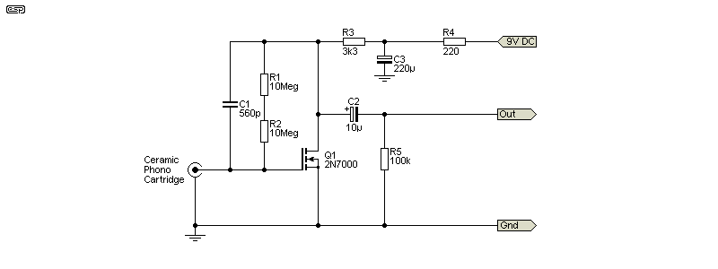
Figure 6 - 2N7000 MOSFET Based Piezo Phono Preamp
There are two 10MΩ resistors in series to obtain 20MΩ, although it will work happily enough with just one - bass response is affected (-3dB at 28Hz with 10MΩ) but that should be fine with most 78 RPM discs. The circuit has an input impedance of about 1.4kΩ at 1kHz, rising at lower frequencies and falling at higher frequencies. This is to be expected, and should not cause any problems. Note that I have not tested this circuit, other than in the simulator. I don't have any 78 RPM discs, and nor do I own a ceramic cartridge, and I would never use a ceramic cartridge with any of my vinyl.
The circuit is included because some people might find it useful. The gain depends on the ratio of the cartridge's capacitance and that of C1. High capacitance pickups will provide more gain, and with a low capacitance type it will be less. Assuming a cartridge capacitance of 1,000pF (1nF) the gain of the circuit as shown is roughly 4.8dB (×1.72). Gain can be modified by changing the value of C1 (560pF as shown), with a lower value providing more gain, but with a higher bass -3dB frequency. The converse also applies. The output impedance is around 100 ohms, but the minimum suggested load impedance is 10k. The simulator says that distortion is about 0.03% with a 10k load, and this is well below the distortion I'd expect from a shellac disc. Be aware that some ceramic cartridges have a very high output level - I checked out a few specifications and some can (allegedly) output up to 3.6V RMS. Most will output around 500mV to 1V (RMS).
High impedance circuits pose 'special' problems. If you use a very high resistance, it's susceptible to surface leakage. This can be due to contaminants on the resistor, leakage through the PCB or prototype board and/ or high humidity. The bootstrap technique eliminates most of these effects, but if not done properly causes problems of its own. The circuit described has been designed to minimise any adverse effects (especially unwanted very low frequency boost). It's a little more complex than others you might come across, but it's a technique that I've used with success on a number of occasions.
High impedances are also susceptible to hum fields, and you need extraordinarily good shielding to reduce the hum to manageable levels. This is a great deal harder than it may seem, and it gets worse as impedance is increased. Cable capacitance attenuates the signal from the piezo, and this becomes more troublesome with low output levels. However (and contrary to what you might expect), cable capacitance does not affect high frequency response, only the signal level. A capacitive voltage divider is just as valid as the more common resistive divider.
Charge amplifiers are uncommon for piezo audio pickups. I suspect that this is due to them being somewhat 'unconventional', although they are widely used in instrumentation systems. Their greatest advantages are the (almost) complete freedom from cable capacitance causing gain variations, and a dramatic reduction of cable noise (triboelectric effects). They also have a very low input impedance, which provides other benefits.
As with most ESP projects, these circuits are intended for inspiration and experimentation. This is especially true of the charge amplifier, which is seriously under-represented in audio circuits. This is unfortunate, because it has many very desirable attributes, all primarily due to its very low input impedance. This is exactly the reverse of other designs.
I have deliberately not included any equalisation (EQ) circuits for the preamps, as this depends on too many unknown factors. Piezo pickups can be under the bridge, or used as contact microphones (stuck or screwed to the body of the instrument). The sound from each method is usually very different, and EQ has to be arranged to suit. Under-bridge pickups can exhibit considerable high frequency boost, and unwanted microphony can be a problem [ 4 ]. EQ is often best kept separate from the piezo preamp itself, as this will usually be easier for the player to operate. The output impedance from all circuits is 100 ohms - low enough to allow any reasonable cable length without problems.
Hopefully, readers will find these circuits useful, and they are capable of good performance, with no bad habits. Bootstrapping inevitably requires compromises, but it's only necessary if the capacitance of the piezo transducer is very low, and (for whatever reason) a charge amplifier is unsuitable. The precautions included in the Figure 1 circuit ensure that it remains well behaved, pretty much regardless of the capacitance. However, any bootstrap circuit relies on some degree of positive feedback, which can make the circuit noisier than expected.
Of the options covered, my favourite is the charge amplifier. It's an uncommon design for audio, and that's a real shame because it has so many advantages. If I ever happen to need a piezo amplifier for another project, it will use a charge amp! The advantages outweigh any minor disadvantages. Yes, there a little bit more thermal noise (hiss) but almost no hum. The latter is almost inevitable if you use a high input impedance.
While there are many other piezo preamps on the Net, many use JFETs which are now hard to obtain, and a few others are well thought out. There are more bad examples than good, so beware.
 Main Index
Projects Index
Main Index
Projects Index