

|
| Elliott Sound Products | Project 197 |
A common requirement with subwoofers and bass enclosures in general is for some boost prior to rolloff. Vented (ported) enclosures are particularly vulnerable to energy below the port tuning frequency, and a high pass filter is always a good idea. Ideally, it should have a very steep slope, but a 12dB/ octave filter is (just) sufficient to prevent over-excursion. By adding some boost, you may be able to make the enclosure a little smaller than otherwise needed, but with a comparatively low tuning frequency.
Unfortunately, this almost always results in a dip below the speaker's resonant frequency, and a simple boost circuit can restore the response, while minimising power delivered at frequencies that the speaker enclosure can't reproduce. I used WinISD Pro to produce the graphs shown below, and they are for a woofer with fs of 22Hz, in a 103 litre box tuned to 19Hz (half an octave below the optimum tuning frequency of just under 27Hz). When the filter is added, the response is improved.
This project is designed to be used with a dual supply of (typically) ±15V. Because the circuit uses dual opamps, you get two channels, and both should be configured identically. There is nothing especially new or different here, but it's intended for those occasions where you just need the extra half octave from a box that can't get that low. Of course, one can use a Linkwitz Transform circuit (see Project 71), but that doesn't have a high pass filter ... well it does, but it's not very good. It's also designed for use with sealed enclosures. This circuit can be used with either, but there will be always be constraints on the box size and loudspeaker parameters.
The circuit is shown below. Two channels, with a non-inverting gain that is set to provide the desired boost. Below the nominal -3dB frequency, the response rolls off at 12dB/octave. Do not exceed a gain of three, or the circuit will become a low frequency oscillator ... at full power !. It should be apparent that DC operation is not possible, and nor is it desirable.
The following two graphs show the un-equalised and equalised response of the speaker. It's a 380mm (15") driver, with a free air resonance of 22.3Hz, and used in a 103 litre box tuned for 19.4Hz. WinISD says that the optimum tuning is for 27.5Hz where response is -3dB. Reducing the tuning frequency by ½ octave ( 27.5 / 1.414 ), I used a new tuning frequency of 19.5Hz. Without EQ, the response is predictably very poor (-3dB at 34Hz).
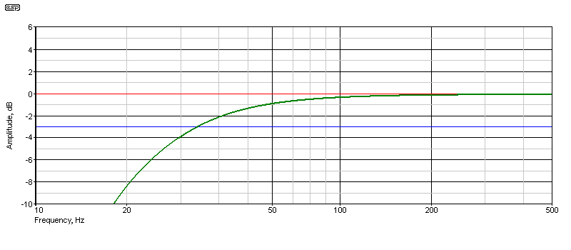
Figure 1 - Un-Equalised Woofer
Next, we apply an equaliser, having a nominal rolloff of 20Hz, and with a Q of two - this causes the low frequency to be boosted by 6dB before it rolls off. The basic parameters of the driver and box are unchanged, but the LF boost moves the -3dB frequency down to 19.4Hz - a very worthwhile extension. Both graphs were captured directly from WinISD Pro, but converted to reverse the normal black background. This tuning was used by Electro-Voice (EV) fairly extensively in the 1970s, and is also known as Thiele's 6th order alignment, where the tuning frequency is reduced by ½ octave, and the response restored by using a 2nd order high pass filter with a Q of two. EV referred to this as a 'step-down' tuning, and offered enclosure plans that allowed one vent (port) to be blocked off to achieve the desired response.
Given that the optimum tuning frequency provides a -3dB frequency of 27.5Hz, and the 'step down' -3dB frequency is 19.5Hz (with the boost circuit), that's a full half octave improvement at the bottom end. Yes, you pay for it in terms of the power needed, but compared to a sealed enclosure with a Linkwitz Transform circuit, there really isn't any comparison.
One may well ask how (and why) it's a 6th order alignment. A 'normal' tuned enclosure is ideally adjusted to be a 4th order Butterworth (maximally flat amplitude) acoustic filter, and response rolls off below the cabinet's tuned frequency at 24dB/ octave. Adding a 2nd order electrical filter makes the rolloff 6th order, meaning that the acoustical rolloff will be 36dB/ octave below the tuned frequency. The addition of boost prior to rolloff in the electrical filter will (in an ideal case) result in a 6th order Butterworth filter.
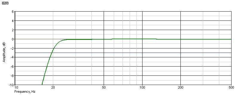
Figure 2 - Equalised Woofer
Note that the two graphs shown above are close to being optimised, and were the result of an experiment with WinISD to see if the process works. It does, and it will work well only if the enclosure and its tuning are worked out carefully. This doesn't mean that you necessarily need to calculate everything exactly, especially since the circuits shown below let you experiment. It may well turn out to be the saviour for an enclosure you already have, but that doesn't match any modern loudspeaker driver.
The basic circuit should be familiar. It's a more-or-less conventional second order high pass filter, but rather than having to use 'odd' (and different) values for the resistors and caps, they are all the same. This is sometimes known as an 'equal component value Sallen-Key' filter, although in reality it's not actually a Sallen-Key filter at all. No matter, the semantics are of little interest when all you want to do is apply a bit of low-frequency boost.
The Q of the filter is varied by changing the gain. With unity gain, the Q is 0.5, so it's a Linkwitz-Riley high pass. When the Q is set for 0.707, the response is Butterworth (maximally flat amplitude), and as the gain is increased, there is boost before the roll-off. Any response anomalies are likely to be far less than the typical disturbances caused by room boundaries. The frequency was set for 19.5Hz, using 220nF capacitors and 37k resistors for the filter circuit (actually 44.2Hz, but the difference isn't worth worrying about).
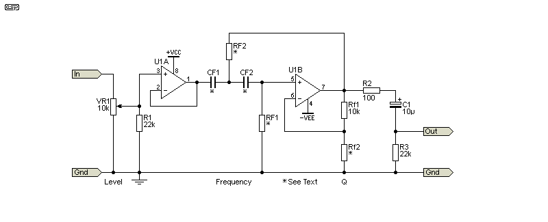
Figure 3 - Filter With Boost Circuit Diagram
The schematic is shown above. Only one channel is shown, so if you need it in stereo the circuit must be duplicated. CF1 and CF2 are the same value, as are RF1 and RF2. The frequency is determined by the usual formula, but it does shift a little as the gain is changed. Mostly, this will not be noticeable as the shift is small and loudspeaker drivers are not precision devices. 'Rf' (lower case 'f') refers to the feedback resistors. With Rf1 at 10k as shown, Rf2 must be 6k or greater. At 5k or below, the circuit will oscillate at the tuned frequency. For 3dB boost, Rf2 needs to be 8.2k (not shown in Figure 4).
fpeak = 1 / ( 2π × CF × RF ) So ...
fpeak = 1 / ( 2π × 100n × 36k = 45Hz
Use the opamps of your choice, with either the NE5523 or OPA2134 being recommended. You can use 4558 or TL072 opamps for non-critical applications. Remember that the circuit has gain so the input level pot (VR1) is there to ensure that the level within the circuit is below clipping. You will experience premature clipping if the input level is too high. Bass content (and therefore level) is very different, depending on the kind of music being processed. Anything that already has a very strong bass component is more likely to cause the circuit to clip, and by using the volume/ level control at the input, this is less likely (for the filter, but not necessarily the power amplifier !).
Q is determined by the following formula ...
Q = 1 / ( 3 - G ) (where G is gain/ voltage amplification) And ...
G = Rf1 / Rf2 + 1
Should the gain (and Q) be increased beyond that shown in Figure 4, with a gain of 3 you have an oscillator. Realistically, even a Q of three (gain of 2.667) is a bad idea. That provides 10dB of boost, and your amplifier must have 10dB of 'reserve' power to handle that without clipping. That means that if you normally operate with 100W, the amp may have to be able to provide up to 1,000W with 10dB of boost. This is clearly not sensible, and you risk serious speaker damage if it's even attempted. Most of the time you'd be looking at a maximum boost of around 6dB. This still requires double the amp power, so it's not to be taken lightly.
Note that although the DC connections are shown in the circuits, I have not included the bypass capacitors that are essential. They were omitted for clarity, but anything from 100nF to 10µF caps should be used from each supply rail to ground, with 100nF caps between the IC supply pins - as close as possible to the ICs themselves. Failure to include proper bypassing may lead to opamp oscillation.
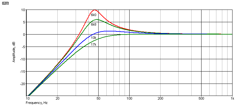
Figure 4 - Amplitude Response With Different Q
For the graph shown, the output was taken from the junction of Rf1 and Rf2, so the passband gain remains at unity. Using 17k for Rf2 gives a Q of 0.707 - Butterworth response. The other responses are with Rf2 as indicated on the graph. For all normal EQ, it's best to keep the gain (and therefore the Q) to provide no more than 6dB of boost, and preferably less. The enclosure/ speaker combination shown in Figure 2 shows the response after correction with a Q of 2. That's a gain of 2.5, provides 6dB of boost, and requires Rf2 to be 6.7k (although 6.8k is close enough). The frequency was set for 45Hz for the graph shown.
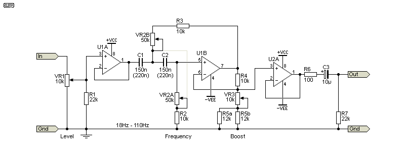
Figure 5 - Adjustable Filter With Adjustable Boost
For testing, ideally you need the circuit to be adjustable. Figure 5 shows how that's done, with a range from 18Hz to 110Hz, and the Q is variable from (close enough to) 0.7 up to 3.0 (note that the internal gain changes as the Q is varied). The arrangement shown keeps the nominal gain at unity, and requires the extra opamp buffer to ensure that external loading doesn't affect the gain (and therefore the Q).
If you use 220nF caps, the frequency range is lowered to 12Hz up to 72Hz. It's likely that either will be fine, depending on your desired low frequency rolloff frequency. Anything much below 20Hz is generally not useful. You must keep the input level low enough to ensure that the circuit cannot clip, and a maximum of around 1V RMS is suggested.
Even then, while the higher frequencies are amplified by about 2.68 times, if you have 10dB of boost added that brings the level up to just about 8.4V RMS. That means a voltage swing of almost ±12V. There is very little headroom, even when using ±15V supplies. Since this is intended to be used for testing, it's unlikely that you'll run into any issues, since most tests are performed at moderate levels.
While the testing circuit can obviously be used in a fixed installation, it would be necessary to have the pots positioned so that people can't fiddle with them. This is especially true if you have children who use your system, or if it's used for sound reinforcement where others have access to the controls. It's an interesting phenomenon that people will often only ask "What does this knob do?" after they've played with it first.
As noted in the intro, this isn't a 'new' application for a high-pass filter. However, it is interesting enough to include in the projects list, and it has some advantages over the Linkwitz Transform circuit. However, it lacks the ability to reduce any response peak as seen in Figure 2. This may be a concern with high fidelity applications, but even there, room boundary effects are likely to cause a great deal more havoc than the gentle hump shown.
With any circuit designed to provide low frequency boost, you need to be very careful to ensure that the driver's excursion remains within limits. This is a little easier with this design than it is with a Linkwitz Transform, but driver excursion below the port tuning frequency will be higher than at resonance, and speaker power has to be limited to a level that won't cause damage. This depends on the woofer, the enclosure, how much boost you provide, and the type of music.
There are no references as such, as this is a common circuit that's been around for a very long time. However, just prior to publication I was sent some additional information about the Electro-Voice implementation of this technique, in an article by Don Keele Jr. and published in AudioXpress in September 2017, as well as an AES paper by the same author, presented in 1974. It's obvious that it's not at all 'new' information, but hopefully others will find it as interesting as I did. The data I was sent does not appear to be available on-line, but you might find similar info if you search hard enough.
For more information on the design of opamp circuits (including filters), see the Designing With Opamps series. Filters are covered in detail in sections 2 and 3.
 Main Index
 Projects Index