
|
|
| Elliott Sound Products | Project 165 |
Valve (or vacuum tube) testers are generally intended to be "all things to all (wo)men", and as such are designed in such a way that the valve being tested will never be stressed. As a result, they aren't much use for testing power valves because the current (and often the voltage) is too low to let you see what the valve will do when it's installed in an amplifier.
The tester described here is only for use with power valves, and it's assumed that anyone building and using it will be skilled in the art of servicing and will have the necessary equipment to hand to be able to use the tester. It's not for the faint-of-heart, and it's quite capable of destroying an output valve if it's not used properly. The test equipment that you must have available is as follows ...
The tester is specifically designed to let you run the valve in normal quiescent mode, or to push the valve being tested hard so you can approximate the operating conditions in an amplifier. The main power supply pulses the anode voltage at 50Hz or 60Hz, so you can pull considerable current while keeping the valve's plate dissipation within average ratings. The power supply uses a DC voltage clamp, so a nominal 230V RMS input provides up to 650V for the plate. The screen grid (G2) can be fed from the main supply or a half voltage DC (up to 325V DC), allowing you to select the operating mode that most closely represents the amplifier operating conditions.

| Note Carefully: The transformer shown in Figure 1 must be used, and a Variac is then used to vary the primary voltage. In countries that use 230V mains, a 1:1 isolation transformer (not an autotransformer) is needed, and for 120V countries you'll need a step-up transformer from 120V to 230V. The transformer should ideally not be a toroidal type, because the output is half-wave rectified. You will need a transformer rated for at least 1A output, and you'll need to test it to ensure that the core doesn't saturate when wired as shown and current is drawn from the secondary. |
The tester is fundamentally evil - as noted above it is quite capable of destroying an output valve if you aren't 100% certain about how to use it, or if you make an error in your calculations beforehand. On the positive side, you can test any output valve to full rated plate dissipation, and a flaky or faulty valve won't survive.
| WARNING This project uses high voltages internally, and requires the use of a Variac to control the plate (anode) voltage. Mains wiring is also involved, and in some countries it may be unlawful to perform any mains wiring unless suitable qualified. The circuits described can cause serious injury (including death) if the constructor is inexperienced or unable to perform high voltage wiring to the required standards to avoid contact. |
Should you choose to ignore the above warnings, there is a real possibility that you won't survive. The project might appear simple, but it is filled with inherent dangers if you aren't well versed in the construction of high voltage circuitry.
The schematic of the tester itself is shown below. The adjustment of plate voltage is done externally with the Variac. You might be fortunate and have a suitable transformer with multiple voltage taps available, but it's expected that this won't be the case for 99% of potential constructors. The grid bias voltage can be taken from an external power supply or from the supply circuit shown further below.
Using external supplies is cheap if you already have them, but it means that it will take some time to set up the required equipment before use. A small error (such as forgetting to turn on the grid bias supply) may destroy a perfectly good valve if you aren't careful. In addition, you need a 6.3V supply for the valve heaters. By including the bias and heater supplies in the tester, you reduce clutter and the likelihood of mistakes during setup. The 'HT On' switch allows you to run a valve with no HT, or to switch off the HT when changing valves. Not all Variacs have a switch, but if yours does, the 'HT On' switch can be omitted.
Figure 1 - Valve Tester Schematic
Figure 1 shows the tester circuit. D1 is a voltage clamp diode, and the anode voltage varies from zero (actually -0.65V) up to double the peak voltage of the AC from transformer T1. Although a 1N4007 is capable of withstanding 1kV at up to 1A, a higher spec diode (such as a BY228 or similar - 1,500V, 3A) is more robust. C1 will charge to a DC voltage that's half the AC peak-to-peak voltage. For example, if the transformer output voltage is 100V RMS, the peak plate voltage will be 282V (unloaded) and you'll get 141V DC across C1 (also unloaded). As expected, both of these voltages will fall when a valve being tested draws plate (or screen grid) current. The fuse should be accessible from outside the box the tester is in, because a bad valve can easily fail in such a way that the fuse blows.
The point marked 'X' above the Variac input is where the relay contacts will be wired if you use the protection circuit shown in Figure 6. See Protection Circuits for the details of two viable protection schemes you can use if you wish. The capacitor (C4) across the transformer must be X2-Class (275V AC) and with a value of 100-220nF. The idea is to 'catch' flyback spikes from the transformer that may cause diode failure. These will occur if there's an intermittent A-K short in the valve being tested. This can cause a high voltage flyback voltage across the transformer secondary, which can cause diode failure.
C2 (10nF) and R5 are optional, and can be added if there is any sign of instability from the valve under test. R5 is a grid 'stopper' (as used in almost all amplifiers), and C2 should be rated for 250V AC (X2 Class). This is because C2 may get the full supply voltage across it if the valve has an internal short. You can also use a pair of 22nF, 630V caps in series if these are easier to obtain. D3 is included so the transistor won't be damaged if the valve has an internal short.
When testing, select the 'Supply Type' based on the amplifier's topology. If the plate and screen are fed from the same (or close enough) voltage, the 'Single/ Triode' connection will give the best results. If the amp uses a half-voltage supply for the screen grids (typically around 250V) and a higher (e.g. 500V) plate supply, then use the 'Split/ Pentode' connection. Any valve can be tested using both methods, and that will often give you a better idea of the valve's performance.
|
| WARNING: If you have the tester set up and operating happily in 'Split/ Pentode' mode, the grid bias voltage must be increased (made more negative) before you switch to 'Single/ Triode' mode. If you don't, the valve will draw excessive plate current and may be damaged. Adding some form of protection is highly recommended. |
There are many options of course, and that shown below is only a suggestion. The end result will depend on the transformers you have available, so the grid bias supply may use a single 60V winding and a bridge rectifier, rather than the voltage doubler shown. In many cases, you'll need to have two transformers - one for the grid bias supply and another 6.3V transformer for the heater supply. Note that the AC input to this part of the circuit must not come from the Variac - it's connected directly to the mains active (live) and neutral.
Figure 2 - Power Supply For Heaters & Control Grid 
The bias supply needs to be around -80V before the zener regulation. If yours is higher or lower, you'll need to re-calculate the value of R1. It needs to pass about 6mA, as this allows for 3mA drawn by the 22k load (R10 in Figure 1) after the adjustment transistor (Q1). I've shown a 27V and a 33V zener in series because they are commonly available voltages, but you can use 2 x 30V zeners if available. 1W zeners are the absolute minimum, and they will run quite warm. C1 and C2 should be rated for at least 63V with the supply as shown.
Resist the temptation to use a high voltage winding with a resistive or capacitive divider to get the grid bias supply. While it can be done, it usually means that the supply's impedance will be too high and it may take some time before the full -60V becomes available. This can be very dangerous for the valve being tested, as there may not be enough grid voltage to ensure cutoff so the valve may draw a very heavy current until the bias supply comes up to full voltage.
The heater supply must be earthed as shown. This ensures that an internal short to the heater (not uncommon, usually due to arc damage to the valve base) will blow the fuse. The chassis must be earthed to the mains earth for safety.
Unlike most testers, you'll only need two (or maybe three) valve sockets, wired permanently. There is no facility to change the valve base pinouts, as that would make a simple project very complex, and most technicians will work with a limited number of output valves - most commonly for use in guitar amps. The most common octal based valves are the 6L6 (and variants thereof), EL34/ 6CA7, 6V6, KT88 (plus variants), and 5881. Noval (miniature 9-pin) output valves aren't as common, and providing for EL84/6BQ5 types will be sufficient for most work. If there are others that you use with different pinouts, simply add another valve base and wire it accordingly. Make sure they are clearly marked if there are identical sockets that are wired differently!
It may be necessary (with some valve types) to include an alternative heater/ filament voltage. Triodes can be tested, but the 'Supply Type' switch has no effect because there is no screen grid (but you knew that already.  You can also include provision for valves that have an anode top-cap, but beware of the high voltage present!
The unit should be built into a suitable case that protects the user against accidental contact with the HT, and good quality (preferably ceramic) sockets should be used. You can also add a meter to measure the grid voltage, using a 50µA moving coil or a digital panel meter. This makes it easy to set up known conditions for different valve types. Of course, you can also use an external multimeter. The plate voltage is measured by the oscilloscope, and waveforms taken from a 5881 beam power valve are shown below.
This valve tester is intended for construction and use by experienced hobbyists and technicians. It's not a general purpose tester, and as described is suitable for testing power output valves. Twin triodes and other preamp valves cannot (and must not) be connected, as they will almost certainly be stressed well beyond their ratings.
For matching valves, first set the maximum (peak) anode voltage to that used in the amp, then adjust the negative grid bias to get the wanted cathode current (somewhere in the range of 20 to 60mA). Always start with a high grid voltage and adjust it down, or you risk permanent valve damage.
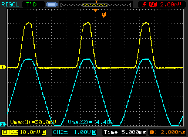
Figure 3 - 5881 Valve In 'Single/ Triode' Mode
In Figure 3 we see the valve tested with a single supply, which pulses up to about 450V. The screen and plate are tied together, and you can see the current pulse developed once the voltage is sufficient to cause conduction. Cathode current peaks at 30mA (30mV peak across the 1 ohm cathode resistor). The divider in the anode monitor circuit divides the voltage by 100, so if we measure 4.5V peak, that equates to 450V across the valve. Grid bias was adjusted to mimic a typical Fender output stage, with a bias voltage of -48V. Peak dissipation is just over 13W.
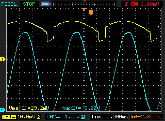
Figure 4 - 5881 Valve In 'Split/ Pentode' Mode
Performance is very different when there's a steady screen voltage present, as produced in 'Split/ Pentode' test mode. The peak current is again about 30mA, but you can see that the plate voltage causes a relatively small change of current over a wide range of voltage. Naturally, when the plate voltage falls to zero, the current falls, and the remaining 15mA (average) is screen grid current. The peak plate voltage is higher this time (just over 600V), and peak dissipation is now 18W. The bias voltage was -28V for this test. Note that plate current is maintained until the voltage is almost zero.
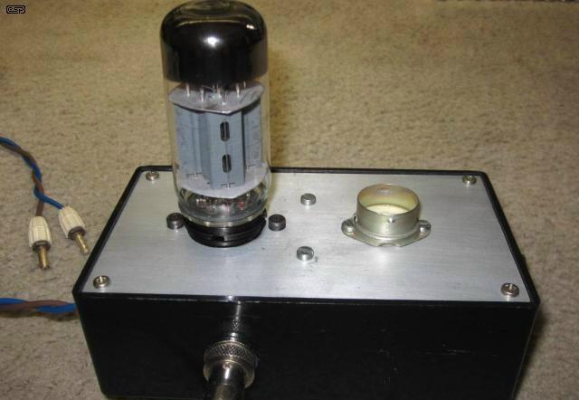
Figure 5 - 5881 Valve Installed In Prototype Tester
Don't expect to make perfect sense of the readings you get from day one. It will take a while (and many tests) before you are completely comfortable with this tester and the way it behaves. While it's also possible to inject a signal so that gain can be measured, this hasn't been included because the low frequency, high amplitude ripple makes AC signal tests quite irksome. Transconductance (gain) can still be measured - simply change the grid voltage by (say) 1V, and measure the peak change of plate current in milliamps. This gives you transconductance in mA/V, which can easily be converted to mhos or Siemens if you prefer ...
1mA/V = 1,000µmhos = 1,000µS
Output valves (and especially beam tetrodes and pentodes) generally have fairly high transconductance. This is expected of course, because the input voltage swing is limited by the negative bias voltage (unless grid current is allowed), and they are expected to deliver power to the load. For example, a 6L6-GC has a transconductance between 5,200µmhos (5,200µS or 5.2mA/ V) and 6,000µmhos. The datasheet I have for the EL34 says its gm is 11mA/ V (11,000µS = 11mS).
It is possible that you'll have to add some degree of filtering, because the valves being tested might show some oscillation under some conditions (see comments above about C2 and R5). This is up to the constructor to figure out, because the wiring layout will have some effect. The valve's control grid should be earthed for AC by including C2 and R5 as shown. In case you were wondering, the grid is supplied via a 220k resistor because most amps have a similar value from the bias supply. By duplicating this, valves that are leaky (due to gas or base leakage for example) will misbehave and let you know there's a problem. Without R4, you may not notice anything amiss until the valve is installed in an amplifier.
Because this tester can drive a valve to higher than normal cathode currents, some may consider the fuse shown in Figure 1 to be inadequate. It's hard to argue with this - it will take some time for a 500mA fuse to blow, and permanent valve damage can occur before the fuse opens. Most valves can tolerate even quite severe overloads for short periods, so protection that is not instantaneous is perfectly alright if done sensibly.
There are a three protection options, as described below ...
Resettable Fuse
The first option is to use a resettable fuse (a positive temperature coefficient (PTC) thermistor), rated for around 140mA at 250V RMS. You'll need to see your preferred supplier's website to see if they have anything suitable. If you decide on this option, the resettable fuse should be in series with the 500mA fuse. Be aware that a resettable fuse is not instant, and can take a few seconds before it becomes a high resistance. This has been tested and it works fine, with no damage to the valve being tested. The only hard part might be finding a suitable resettable fuse. The cold resistance needs to be at least 25 ohms.
The fuse must be able to operate within a couple of seconds with typical overloads, or the valve under test may be damaged. You will almost certainly have to run some tests on the resettable fuses available from you supplier to find one that will provide the level of protection you need.
Electronic 'Fuse'
Alternatively, the circuit shown below is intended to release the relay (RL1) at a preset current. It looks like overkill, but the cost is actually quite low - especially if you have most of the parts to hand. The circuit turns off the power when the cathode current exceeds the preset value, and it stays off until you press the 'Reset' button. With the values given the circuit will trip with just over 160mA peak. The current is set by the ratio of R2 (10k) and R3 (330 ohms), and that gives a reference voltage of ...
VD = ( R2 / R3 ) + 1
= ( 10k / 330 ) + 1 = 31.3
Vref = Vin / VD = 5.1 / 31.3 = 162mV
When the voltage across the 1 ohm cathode resistor (in Figure 1) exceeds 162mV (162mA), the output of U1A falls, turning off Q1 and releasing the relay. A small current is fed back to the input of U1A to ensure that it latches, and this is via Sw2 ('Reset' pushbutton). Without the feedback, the relay would chatter violently and the arc drawn may damage the contacts. C3 is a 'power-on reset', which ensures that the valve's power supply is turned on by default when the heater supply is switched on. Note that the second half of U1 is not used, and that particular IC was selected because of it's input and output characteristics, ready availability and low cost. Do not use other opamps types because most will not work in this circuit.
Figure 6 - Protection Circuit Schematic
The rectifier is a voltage-doubler, and converts the 6.3V AC to about 16V DC. C1 and C2 should be rated for 25V or more. This supply is used to power the opamp (half of an LM358) and the relay, and also provides the reference voltage via the zener regulator (R1 and D3). The relay coil should be a 12V type, and R9 is selected to provide no less than around 10-11V to the relay. A fairly typical 10A relay will have a coil resistance of about 270 ohms, so R9 should be in the order of 100 ohms. This must be verified with the relay you intend to use though.
Note that there is a 470 ohm resistor (R8) in series with the relay's back-EMF diode (D5). The resistor is used to ensure a fast relay release time, but it also means that the voltage across Q1 will rise to almost three times the supply voltage when it turns off. Q1 needs to be rated for a minimum of 50V. You can reduce the peak voltage by reducing the value of R8, but doing so will increase the relay's release time. If you want to know more about relays and how to use them, see the Relays article. As a rule-of-thumb, the relay coil's flyback voltage is roughly ...
Vp = ( Vs × Rp / Rc ) + Vs
where Vp is the peak voltage across Q1, Vs is the supply voltage, Rp is the parallel resistor (R8) and Rc is the relay coil resistance
Note that Vs is 16V, and the effective coil resistance is the actual resistance plus any external resistor (R9)
Vp = ( 16 × 470 / 370 ) + 16 = 36.2V
With R10 being 2.7k as shown, LED current is 5mA or so. The LED is on when the circuit is active, and will go out if the over-current detector trips. If that should happen, make sure that you reduce the supply voltage to the valve to zero before you press the reset button. If a high fault current flows the relay will buzz because its drive circuit has no hysteresis (so the relay cannot latch) while the button is depressed. Sw2 is a normally closed push-button.
Hint: If you use the protection circuit shown in Figure 6, you have a spare opamp (U1B - half of the LM358) that can be used to amplify the signal across the cathode monitor resistor. If you provide a gain of 10, the current will be easier to measure on your oscilloscope, and will have a scale of 10mV/ mA. A peak cathode current of (say) 50mA will give an output of 500mV peak.
Audible Alert
An audible alert will give you a sound, and the loudness is determined by the current drawn. Piezo 'buzzers' (Sonalert™ or similar) have an oscillator built in, and only need a source of DC to operate. They usually generate a tone at around 3kHz, and most will operate with a fairly low voltage. 2V to 24V is a common voltage range for typical units.
The buzzer (or 'squeaker' if you prefer) has to be protected from excessive voltage created at switch-on as the 47µF capacitor charges, or under fault conditions. To sense the current, the piezo buzzer is connected across a resistor that will give enough voltage at maximum current to make its presence heard. Since the maximum suggested peak current is around 150-200mA, a 47 ohm resistor will develop about 7V across it at a current of 150mA, but the voltage can be a great deal higher under fault conditions. A 10W resistor is recommended, with the buzzer and protective zener as shown below. The zener diode needs to be rated for at least1W. Peak dissipation may be much higher, but the average will normally be well below 1W.
Figure 7 - Audible Alarm Schematic
The 47 ohm resistor is wired in series with the 500mA fuse. Make sure that all circuitry is well insulated from the chassis, and is inaccessible, because it operates at a high voltage. The diode ensures that the piezo buzzer only gets the correct polarity, and the resistor and zener network prevent high instantaneous voltages from damaging the buzzer circuitry. It will 'squeak' briefly when power is applied as C1 (47µF, 350V) charges.
In use, the buzzer will probably squeak softly, with the tone modulated at 50 or 60Hz. It will get louder as more current is drawn, and will be very loud indeed if there's a fault. Note that the circuit is polarity sensitive - it relies on the narrow peak voltage created as the capacitor (C1) charges, which is in turn dependent on the current drawn by the valve. If you get the polarity wrong, the circuit may not give you a warning until the valve's plate current is at a potentially dangerous level - typically over 100mA. This depends on the piezo buzzer, and some will be more sensitive than others, so you'll have to run tests to determine which polarity works best for you.
This is a serious tester, and will exercise an output valve better than almost any other test method. The only test that's 'better' is to run the valve in the amplifier you're working on, but if there's a problem it may cause further (and possibly expensive) failures. If you wanted to go through your collection and sort out any dud valves you've accumulated over the years, this is far better than plugging them into an amplifier and hoping for the best.
Unless you have everything you need already, it won't be an inexpensive project. However, it's an invaluable addition to the servicing gear for professional service people, and there doesn't appear to be anything that comes close on the market. The tester that inspired this design [ 1 ] is all but unobtainable, and if you find one it will probably break the bank.
The design of this project is original thanks to Phil Allison, as are the waveforms shown. Drawings are by Rod Elliott based on an original pen drawing by Phil Allison (Figure 1), text and descriptions are also by Rod Elliott. © 2016, all rights reserved.
 Valves Index
Main Index
Projects Index
Valves Index
Main Index
Projects Index