
|
|
| Elliott Sound Products | Project 151 |
If you really want to play with valve circuits, you need a power supply that can provide a very clean DC voltage, usually up to about 250V. It doesn't need to be regulated, but it does need to be variable and completely hum-free so you can determine the best operating conditions for the circuit you are using, without having 100 or 120Hz hum messing up your measurements. You also need a heater supply, and that needs to be switchable between 6.3V and 12.6V for use with most common preamp valves. This should also be DC.
As regular readers will be aware, I have no plans for valve ('tube') based projects as such, but while working on a recent project and compiling articles for the valve section of the website, I found a need for just such a supply. It was important for me to be able to use parts I had to hand rather than spending money for special bits and pieces, so a means had to be found to get the voltages I needed using transformers I had available.
While most hobbyists won't have these parts, they are readily available and fairly inexpensive, and the two transformers I used were perfectly matched for the job. If you are in the US or Canada (or elsewhere that uses 120V mains), you should use transformers that have 120 and 230V (or 240V) primaries if possible.
The circuit is straightforward, but be warned that as with any project that requires mains wiring and high voltages, you need to be very careful and make sure that the end result is safe, and wired to the appropriate wiring code(s) for where you live. The DC output is also dangerous, and even though there is a current limiter it can still cause a severe electric shock that may cause serious injury or death.
This supply is designed for testing 'small signal' valves, the most common being 12AU7 and 12AX7, possibly 12AT7s, and 6DJ8 and similar valve types. It is not designed to run output stages, and attempting to do so will activate the current limiter, which is set for a nominal 65mA. The limit current will actually be a little less than this, and my test unit starts to limit at about 50mA.
The heart of the supply is the transformers. TR1 should be rated for at least 30VA and TR2 for 20VA, not because of the power drawn, but because of the fact that TR2 is driven in reverse from the output of TR1. If TR1 is made larger than TR2 that will give a slightly higher voltage from the variable supply. Worst case heater current can increase the loading of the input transformer (TR1). Both transformers need a secondary voltage of 15-0-15V, and TR2 should ideally have a 230V winding for the high voltage supply. If you only have access to 120V transformers, you can use a voltage doubler, which is also described below. While you might get away with using transformers with 12-0-12V secondaries, I don't recommend it. When driving any transformer backwards, higher secondary voltages are preferable to keep the current within reasonable limits. You may also find that the heater regulator can't maintain 12.6V with a lower secondary voltage.
 | Note: Do not attempt to drive the second transformer with a voltage that's higher than its rated secondary voltage. Doing so will cause the transformer to saturate, both transformers may be overloaded and they will fail by allowing the 'magic smoke' to escape. This can take some time because of the thermal inertia of the transformer(s) which may lead you to imagine that all is well. |
Figure 1 shows the circuit of the supply. The output of TR2 will be around 210V AC, and when rectified and smoothed this gives a raw supply of about 300V. This is smoothed further by the filter formed by R1 and C2. I specified an IRF840 MOSFET for the series pass transistor because they are fairly cheap and readily available, but any MOSFET rated for 400V or more and at least 50W dissipation can be used. It's not at all critical, and you might even have something suitable in your 'junk box'. The indicator for 12.6V heaters is optional, but well worthwhile. The 'ON' LED will be significantly brighter when the heater supply is switched to 12.6V, and that might be sufficient. Alternatively, you can use the supply with only the 6.3V supply, so 12.6V heaters will be operated in parallel. This eliminates mistakes with the heater voltage, but causes higher heater current.
Figure 1 - Valve Test Power Supply
All unmarked diodes should be 1N4004 or equivalent with the remainder (high voltage) being 1N4007, and all capacitors in the high voltage section should be rated for at least 400V. The MOSFET must be on a reasonable heatsink and insulated from it with mica and thermal 'grease'. It will probably be ok to use a Sil-Pad because the total power isn't very high (up to 20W with a shorted output). Q2 and associated resistors make up the current limiter. If the voltage across R5 (10 ohms) exceeds 0.65V (65mA), Q2 will turn on and remove the gate voltage from Q1 so that the current is maintained at the preset value. R6 is there to protect the base of the transistor against momentary high peak current (although it will probably never happen). You can increase the current rating by reducing the value of R5, and using 3.3 ohms (for example) will let the supply provide about 200mA. If you do this, you will need larger transformers (TR1 & TR2), more filtering capacitance, a lower value for R1 and a much better heatsink for Q1. I'd also suggest a higher power MOSFET, ideally one rated for at least 200W.
Of course, you just might have a suitable transformer with the voltages you need already. If that's the case, you can use it rather than the arrangement shown above, but the voltage ratings for all capacitors must be increased if the output voltage from the transformer is greater than 250V AC. You may also need to use a higher voltage MOSFET if the rectified and smoothed DC is more than 450V DC or so.
Using DC for the valve heaters is strongly recommended, especially if the power supply will be used as part of a test setup. You don't need hum due to heater-cathode leakage if you are trying to measure noise or distortion, because it will mess up the readings rather badly. Using a regulated heater supply also means that your tests can be consistent from one day to another, without having to worry about small cathode temperature variations caused by mains fluctuations. C6 in the heater supply should be rated for at least 25V, but C7 & C8 only need to be 16V (although higher voltage is fine).
With the values shown, the 12.6V output will actually be about 12.57V and 6.3V will really be 6.4V (assuming that the LM317 reference is exactly 1.25V of course). You might want to replace R8 and R9 with 2k multiturn trimpots so you can set the voltage as accurately as you like. R7 should be increased to 2.2k if you use a trimpot.
The HV supply isn't regulated - it's only adjustable. It is not difficult to make a high voltage regulator but in most cases it's not needed, and you need more input voltage headroom to guarantee that the regulator doesn't 'drop out'. The arrangement shown will be more than adequate for the tests that most people wish to carry out. Most of the time the circuit will be subjected to normal mains variations anyway once it's in use, but having very low ripple is essential for taking measurements.
There is one change that you might want to make to the basic circuit shown above. The main transformer (TR1) is used for 'dual duty', in that it provides both the high voltage and heater supply. This means that when the heater supply is connected the high voltage will be reduced because of the regulation of TR1. If you don't like that idea, simply use a third transformer to provide the heater voltage. This ensures that the full HV supply is always available whether the heater supply is connected or not. The transformer used for the heater supply still needs to be rated for around 20VA and needs a 15V winding (with a bridge rectifier) to ensure that the 12.6V supply will be properly regulated (see Figure 2B).
While adding a third transformer will certainly take up more space and cost more, it's worthwhile because you are making a piece of test gear. Test equipment will usually be used for many different projects and will last for many years, so the total cost is not really that high in the greater scheme of things.
If you don't have or can't get at least one of the transformers with a 230V primary winding, you'll need to use a voltage doubler. While perfectly acceptable, you will need more capacitance to ensure that the supply is hum free. A doubler actually needs exactly double the capacitance that's needed with a bridge rectifier, because the two caps are in series so capacitance is halved. They are also lower voltage, and in terms of cost they are probably about the same.

Figure 2 - (A) Voltage Doubler For 120V Transformers, (B) Alternate Heater Supply
The doubler circuit is shown above in Figure 2A. It replaces the transformers, bridge rectifier and first filter cap shown in Figure 1, and its output connects to R1. Everything else remains the same, including the heater regulator. You will have one extra capacitor though. Voltage doublers have a fairly poor reputation, but that is mostly unjustified and/ or just plain wrong. There is almost no difference between a doubler and a bridge if they are designed properly.
Should you decide to use a separate transformer for the heaters, use the circuit shown in Figure 2B. The output connects to U1 (the LM317 regulator) and the low voltage common. The HV- and LV- points can be joined to the high voltage common and/or chassis as desired. The transformer primary must match your mains supply, and connects to the AC supply after the switch and fuse.
The MOSFET and LM317 regulator need a heatsink. The heater regulator may dissipate significant power when used with 6.3V heaters, and the heatsink needs to be substantial in order to keep the regulator cool. Valves such as the 6DJ8 are fairly hungry, and draw around 450mA at 6.3V. The regulator dissipation will be about 6W under these conditions, so don't skimp on the heatsink. You may consider using a fan if you expect to push the limits. If used, it must blow air onto the heatsinks to ensure maximum cooling. A dust filter would be wise - dust, high voltage and humidity play well together, but not in a good way!
There's nothing critical about the circuit, but do make sure that R5 (gate 'stopper' for Q1) is as close to the gate connection as possible. Also, make sure that C7 and C9 are very close to the regulator IC. In come cases, it might be necessary to add another 100nF cap in parallel with C9 to prevent the U1 from oscillating. The remaining parts of the circuit can be wired on tag strips. Don't use Veroboard for the high voltage supply, because the spacing between tracks is too small. It's perfectly alright for the low voltage supply of course.
You can add a meter if you wish, and that would typically be used to monitor the high voltage output. A meter with full scale deflection of 1mA or so is fine. If you have a 1mA movement with a resistance of 200 ohms, you can calculate the series multiplier resistor easily. You need to determine the maximum voltage to be read, so let's assume 300V ...
R = ( 300V / 1mA ) - 200 (meter resistance)
R = 299.8k (use two 120k resistors in series, with a series 100k trimpot)
The multiplier resistance will dissipate a total of 300mW, and you should use a pair of resistors in series to get an adequate voltage rating. You can make the meter switchable for voltage or current, but having a current readout isn't terribly useful because it's so easy to work out how much current a valve circuit draws. If you think it's a good idea, go right ahead. There is a complete article that describes how to set up meter multipliers and shunts - see Meters, Multipliers & Shunts.
I have shown the high and low voltage supplies fully floating, with no connection to earth (ground) or each other. They can be earthed to the chassis and mains if desired, and you may find it more convenient to join the negative leads of both supplies so you'll have HV, Common and LV connections.
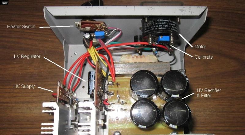
Photo Of Power Supply As Constructed
The photo above shows the insides of the unit I built using the circuit shown in Figure 1. I included a meter because the case I recycled already had the meter installed. The rest of the circuit is almost exactly as described, but I added two extra HV filter caps because I had them available. The high voltage is variable from 0-250V when the heater is connected, but somewhat more with no load on the heater supply. This is fine for the things I need the supply for, but you might get more or less, depending on the transformers you use.
The heatsinks I used are not sufficient if you plan on heavy use. I used the ones seen above because they were to hand, and I know how I'm going to use the supply - usually for fairly short periods at a time, and with mostly light loading. This is a decision I leave to the constructor, but larger heatsinks are preferred. Remember - there is no such thing as a heatsink that's too big!
You need to be very careful that the heater switch is not left at 12.6V when you use 6.3V valves. Failure of the heater is assured if you run it at double the normal voltage. There is no current limiter on the heater supply (other than the inbuilt protection in the LM317) because valve heaters vary too widely and it would be silly to include limiting. This is the reason for the switched LED - it will act as a positive visual reminder that the heater voltage is set for 12.6V.
Although the supply has a current limiter, it's best if it never comes into play. Make sure that you use wire with insulation that's rated for the voltage, and don't use very thin wires for the heaters or there will be too much voltage drop in the wire itself. You can 'lose' a couple of hundred millivolts without much effect on performance, and if the leads are short, general purpose hookup wire may be ok for 12.6V heaters. Use something heavier for 6.3V heaters because the current is a lot higher.
Otherwise, operation is straightforward, and you use it like any other power supply. Just remember that you may have an output of up to 300V or so, and that can do you a mischief at best. At worst, contact may be fatal. For some valve stage topologies, you may need a local filter capacitor to ensure low impedance even at high frequencies. Remember that even straight wires have inductance, and this might cause measurement errors at high frequencies when you are testing your circuit.
 Main Index
Projects Index
Valves Index
Main Index
Projects Index
Valves Index