

|
| Elliott Sound Products | Project 149 |
This equaliser is based on one that was built by John Burnett (Lenard) and me many (many) years ago. It also uses similar input and output stages shown in Project 64. Unlike that project, this is much simpler to build, and it uses octave bands. While it is theoretically possible to have more, the Q of the filters isn't high enough as shown. Q can be increased, but at the expense of more signal loss and therefore higher noise.
It is specifically designed as a preamp or 'tone shaper' suitable for musical instruments - guitar, bass (electric or acoustic) and keyboards in particular. Unlike most conventional graphic equalisers, each slider ranges from fully off to fully on, and not the more conventional +/-12dB or so that is normally available. If the optional tone controls are included in the output section, this circuit is capable of extremely wide tonal variations.
As a result, there is no flat setting (other than all off!). This graphic is designed to be used to create a sound, and is not suitable for hi-fi or other EQ applications. It may be used as an add-on unit to existing instrument amp preamps, tone controls, etc. The flexibility is extraordinary, allowing a hollow 'single frequency' type sound, right through to almost any tonal variant imaginable. With all sliders at maximum, the response is passably flat, and it's unlikely that you'll be able to hear the slight ripple (less than 2dB) in the response.
In use, at least one slider will be at maximum, with the others adjusted to add the tone 'colour' desired. While it can be used with no sliders at maximum, this reduces the signal level through the equaliser and increases noise levels. Only experience with the unit will let you know what it's capable of, as it's unlike almost any other tone control system.
The input circuit is completely conventional, and uses 1/2 of a dual opamp as the initial gain stage. There is no provision for high and low gain inputs, but it is highly unlikely that any guitar will be able to overdrive the input opamp. The first gain stage is followed by the volume control, second gain stage/ buffer. The output of the buffer is fed to the inputs of the filter stages, each of which has an output slider for its specific frequency. The outputs of the sliders are summed using another opamp, and a distortion effect is included in the final output stage. This can be left out altogether if distortion is not desired.
If used for guitar, the frequencies needed only have to range from 80Hz to about 7kHz, but to make the unit more versatile I suggest that the lowest frequency should be 42Hz, and the highest around 12-13kHz. This can be extended if you want. Each filter circuit has an insertion loss of about 2.5dB, but it's impossible to quote an overall gain because it is entirely dependent on the positions of the sliders.
Decisions ?
Unlike the Project 64 equaliser, there really aren't any major decisions to be made. The circuit as described is more-or-less 1 octave for each slider, and as shown the frequencies are as follows ...
| 42 | 87 | 195 | 420 | 870 | 1.95k | 4.2k | 8.7k | 15.6k |
As an option, the final filter can be set a little lower, and 13kHz is suggested. You can change it if you want, and indeed you can change all the frequencies, simply by using different capacitor values. This is described in detail below, in the 'Frequency Response' section. Although I claimed that there aren't any decisions to be made, in reality there are still many possibilities. However, the suggested frequencies make a good mix for guitar and bass (electric or acoustic) and will also suit many keyboard requirements as well.
Figure 1 shows the schematic of the input section. The input stage is configured for a gain of about 12dB (4 times), which can be increased or reduced if desired. To lower the gain, increase the value of R4. The buffer stage as shown has a gain of 2, and has an effective load of only about 1.1k ohms - a difficult load for most opamps to drive. If more gain is needed, reduce the value of R6 as required. It's unlikely that less than 1k would be used for R6, as the gain will be excessive.
I suggest that an NE5532 opamp is used for U1 and U2, because they can drive low impedances without difficulty. Other alternatives are the OPA2134 or LM4562, but they are considerably more expensive. Pinouts are the same for the three types. The NE5532 is critical of supply bypassing, and the addition of 100nF ceramic caps between the supply pins is essential (shown as 'Cb' - bypass cap). These should be as close to the IC package as possible and used regardless of opamp type. Some bulk bypassing is also a good idea, such as a couple of 10µF-100µF caps from each supply to earth/ ground at the DC input to the assembly.
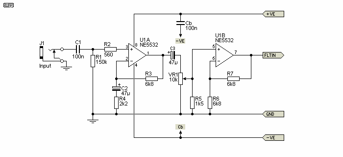
Figure 1 - Instrument Equaliser Input Stage & Buffer
The filters and slider pots (with their mixing resistors) are shown in Figures 2, 3 and 4. The filters are based on gyrators - 'solid state inductors' as it were. Such filters are not wonderful, and they are not as good as multiple feedback types, but they are a great deal simpler. The filters shown use a transistor, which limits the performance even further, but the big advantage is simplicity, low cost and minimal PCB space for the filters.
There is one filter module and one slider for each frequency. Combined with the final mixer stage shown in Figure 6 which includes tone controls and a treble boost switch there will be sufficient range for virtually any instrument.
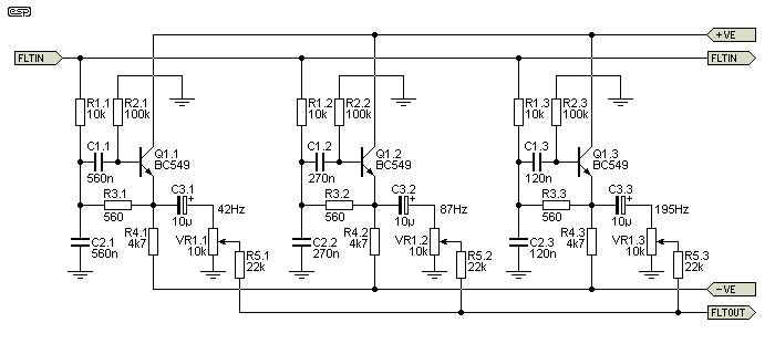
Figure 2 - Filter Bank #1, Slide Pots and Mixing Resistors
The first 3 filters are shown in Figure 2. The input and output buses are common to all the filters, as are the power supply connections. As you can see, each filter is essentially identical, and only the capacitor values are changed to select the frequency. To keep the circuit as simple as possible, the cap values in each filter are the same. The filters need high gain transistors, and I recommend BC549C or direct equivalent. This is the highest gain readily available, and they also have the benefit of being cheap. Do not try to use low gain transistors, because the maximum attenuation of frequencies below the pass band will be too low. At (say) 10Hz, a transistor with a gain (aka hFE) of 150 will reduce the signal by 30dB, while a transistor with a gain of 500 (typical for the BC549C) attenuates to -38dB. You can use small signal Darlington transistors for improved performance. An example is the 2SD1111, with a gain of 5,000
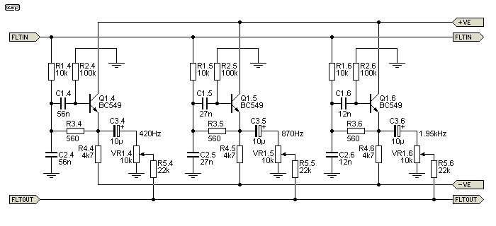
Figure 3 - Filter Bank #2, Slide Pots and Mixing Resistors
The second set of filters is shown above. This is a continuation of those shown in Figure 2. The filters are simply repetition - each is essentially the same as the next, with only the capacitor values changing for each band. Unlike most circuits of this type that you will see, the two capacitors are the same value. This makes the equaliser a great deal easier to wire up than having different values for all the filters. This is done deliberately and would normally make the filters rather poor, but the unusual output connection provides the expected performance.
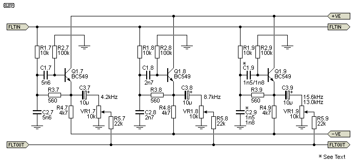
Figure 4 - Filter Bank #3, Slide Pots and Mixing Resistors
The final set of filters is shown above. The last filter can use 1.5nF or 1.8nF caps, giving a tuned frequency of 15.5kHz or 13kHz respectively. As an option, the capacitor (C2.9) can be omitted, so the last filter will behave as a treble control with no defined top end reduction. The cap can be switched if desired. When used with most guitar or bass speakers, the last couple of sliders won't have much effect anyway, as response above around 5-6kHz is severely limited.
The mixer and output stage are shown in Figure 5. The mixer is a conventional 'virtual earth' type, and minimises interaction between the slide pots. The distortion stage is entirely optional, and can be omitted if you don't need it (or it can be switched as shown for maximum flexibility). Use 1N4148 diodes in the clipping circuit, and in conjunction with VR2 (Master Volume) allows the amount of distortion to be adjusted from zero to 'heavy metal' or 'grunge'. It may be necessary to use more diodes than the 4 shown. An additional 4 diodes will raise the maximum output level to about 1.5V RMS before clipping starts. You can also use LEDs as clipping diodes. They have the advantage that the forward voltage is greater, so with (say) 4 green LEDs wired in place of the 1N4148 diodes you'll get up to around 3V RMS before the distortion starts to be audible. The final opamp is a buffer, and contributes no gain.

Figure 5 - Mixer and Distortion Circuits
There is a resistor (R10) that's switched in when the clipping diodes are switched out, and this is optional. The idea is to get a reasonable gain match whether distortion is on or off, and it may need to be adjusted. The final stage is shown with gain, but this is optional. You can change the gain easily by changing R12 (higher value gives more gain). If no gain is needed, replace R12 with a short and omit R13. The gain as shown is x3.2 (10dB). C5 (100pF) reduces the gain at high frequencies. With the value shown, the mixer stage is -3dB at 48kHz, and it can be increased if desired (it's the same in Figure 6 as well).
Using the equaliser is simplicity itself. Just slide the sliders up and down to get the sound you want. There is no 'correct' way to use this equaliser - it is designed to enable you to get the sounds you want. As described above, you can get more of any given frequency by reducing the value of the mixing resistor, but there is a limit to how much noise is tolerable.
The total gain of the unit (with all sliders at maximum) is about 8.2 times for the input stage, and 1.25 for the filters after summing. This gives a total gain of around 10 (or 20dB), not including the output stage where gain is optional. Actual gain will be different, depending on the slider setting, and can be changed in the output opamp as described above, or by changing the value of R9 (lower the value for less gain and vice versa) or R7 (lower value gives more gain). If you change the gain structure, be careful that the input gain (changing R7) is not made too high, or you will get distortion with high level inputs.
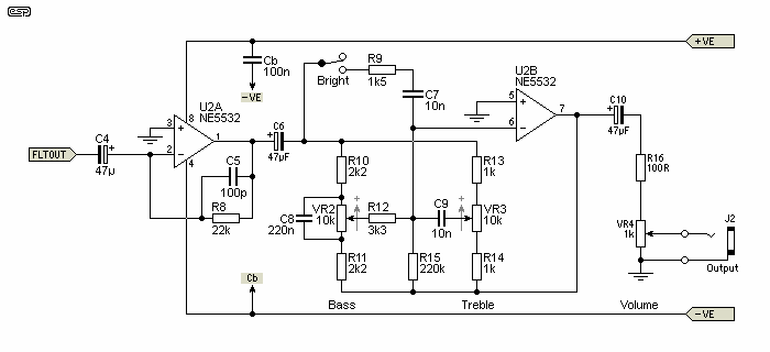
Figure 6 - Alternate Mixer and Tone Control Circuits
Figure 6 shows an alternative to the previous mixer and output stage. This includes tone controls, and a 'bright' switch for additional treble boost. This is likely to be more useful for guitar and bass (as opposed to keyboards and other signal sources), because most guitar amps have (and usually need) prodigious treble boost. Including a bass tone control adds versatility and makes the equaliser more of a general purpose system. Using a low resistance pot at the output (as the 'master' volume control) means that it may still quite easy to get distortion by increasing the input volume and reducing the output level. Total gain is still 20dB, but there is no option to provide additional gain from the tone control stage. Gain can be increased by increasing the value of R8 (this works with either output section). If R8 is increased above 47k (47k gives about 8dB of gain), C5 has to be made smaller or there will be excessive HF rolloff.
The tone control frequencies can be changed if desired. Using a larger cap for C8 (bass) will make it operate from a lower frequency (which will reduce the available boost) and vice versa. Use a smaller cap for C7 (bright) and/or C9 (treble) to increase the turnover frequency (again, this will result in less overall boost). If you happen to think you need more treble boost (you are joking, aren't you  ) then reduce the value of R9 and increase C7. Making them 1k and 22nF will increase the maximum boost to about 22dB at 10kHz.
It is unusual to use Baxandall feedback tone circuits in a guitar preamp, but they are more useful here than a more traditional 'tone stack' as used in the Project 27B guitar preamp. Maximum treble boost is about 14dB without the bright circuit, and just under 22dB with (both at 10kHz). The maximum bass boost and cut is 12dB and -14dB at 40Hz (about +13dB and -15dB at 20Hz).
A word of warning. Don't expect this preamp to be especially quiet, because it won't be. Use of a low noise opamp for the input stage and mixer helps, but as with all guitar preamps, some noise is inevitable. This is made worse by all the filter circuits, but each only adds noise in its own band, so the cumulative noise is not as great as it otherwise might be. Using the distortion control or treble boost will increase noise, and this can be dramatic at full gain. In reality, this is not much different from a conventional guitar preamp that is turned up LOUD to get the same distortion. The more gain you have, the greater the noise.
Figure 7 shows the response of each filter, and the voltage obtained when all sliders are at maximum. There is some ripple in the response as you would expect, but it's generally below 1dB. The graph includes the final filter set to 15kHz with 1.5nF caps - it will be a little different with 1.8nF caps (13kHz). The tone control response is shown in Figure 8, but without the HF boost setting.
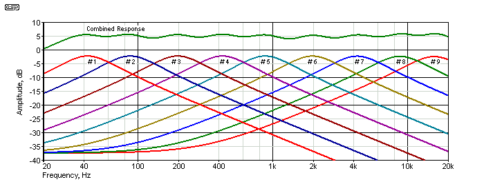
Figure 7 - Frequency Response
The tone control responses were taken with the two pots at 0% (maximum cut), 25%, 50% (flat), 75% and 100% (maximum boost). When combined with the extraordinary flexibility of the graphic equaliser, the range is truly vast. No graphs or charts can ever tell you what something will sound like, but it should be obvious that there are few limitations with the combined circuits.
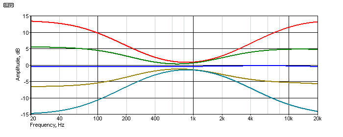
Figure 8 - Tone Control Frequency Response
The table below shows the filter frequencies you can expect with every capacitor value between 1µF and 1.2nF. 1nF caps aren't included, but will give a frequency of 22.6kHz - too high to be useful. The progression provides frequencies that are inversely proportional to the capacitor value, and because the standard values are more-or-less logarithmic, so too are the frequency intervals. Although in theory you could use every value shown, I doubt that many people would think that a 36 or 37 band equaliser was a good idea. Besides which, a vast number of frequency bands is not needed for a tone shaping circuit, because it's intended to create a sound, not to try to compensate for deficiencies.
| Capacitance | Frequency | Capacitance | Frequency | Capacitance | Frequency |
| 1 µF | 22.7 Hz | 100 nF | 226 Hz | 10 nF | 2,260 Hz |
| 820 nF | 27.6 Hz | 82 nF | 276 Hz | 8.2 nF | 2,760 Hz |
| 680 nF | 33.3 Hz | 68 nF | 333 Hz | 6.8 nF | 3,330 Hz |
| 560 nF | 40.4 Hz | 56 nF | 404 Hz | 5.6 nF | 4,040 Hz |
| 470 nF | 48.1 Hz | 47 nF | 481 Hz | 4.7 nF | 4,810 Hz |
| 390 nF | 58.1 Hz | 39 nF | 581 Hz | 3.9 nF | 5,810 Hz |
| 330 nF | 68.6 Hz | 33 nF | 686 Hz | 3.3 nF | 6,860 Hz |
| 270 nF | 83.6 Hz | 27 nF | 836 Hz | 2.7 nF | 8,360 Hz |
| 220 nF | 102.8 Hz | 22 nF | 1,028 Hz | 2.2 nF | 10,280 Hz |
| 180 nF | 125.6 Hz | 18 nF | 1,256 Hz | 1.8 nF | 12,560 Hz |
| 150 nF | 151.3 Hz | 15 nF | 1,513 Hz | 1.5 nF | 15,130 Hz |
| 120 nF | 189.9 Hz | 12 nF | 1,899 Hz | 1.2 nF | 18,990 Hz |
In the above table, the values used in the 9 filters are shown in bold. If you wish, you can use any other series of caps that will provide higher or lower frequencies. For example, you might want to make the first filter run at 33Hz, so you'd use 680nF, 330nF and 150nF for the first 3 filters, then use the values divided by 10 (68nF, 33nF, etc.) for the next 3 filters, then divided by 10 again (6.8nF etc.) for the last three filters.
The simulated inductance of a gyrator is calculated based on the resistance and capacitor values selected. In the above filters, the resistors are R2 and R3 (.1, .2, .3 etc.), and the capacitor is C1. The formula is based on using an opamp, but it's not far off for transistors as shown ...
L = R2 × R3 × C1 So for example ...
L = 100k × 560 × 100nF = 31.36H
Now it is possible to calculate the resonant frequency ...
f = 1 / ( 2π × √( L × C))
f = 1 / ( 2π × √( 31.36 × 560nF ) = 38Hz (close enough)
This is a little lower than the above table claims, and that's because the transistor has finite gain and is a bit 'imperfect'. No matter, because everything is shifted by a similar amount, and the end result will be as described. At resonance, the gyrator inductor and capacitor have the same impedance, which for the example above is 7.49kΩ for both (again, close enough). Combined with the 10k feed resistor for each filter, this gives a theoretical Q of around 1.33, however it's a little less because the 560 ohm resistors appear in series with the gyrators, and that reduces the Q.
Naturally, you may change the frequencies around to suit yourself. If you wanted to use ½ octave intervals, you could use the sequence of 560nF, 390nF, 270nF, 180nF, 120nF etc. You will need to increase the Q of each filter, so R1.1, .2 (etc.) would have to be increased to around 15k. Naturally, that means twice as many filters as shown above, unless you only want to tailor a part of the frequency range. This would complicate the design, and won't be covered unless there is interest expressed by readers.
To power the circuit, any power supply capable of ±15V (±12V will usually work fine) will do, provided that it is capable of at least 50mA, and preferably 75mA or so. With the suggested ±15V supplies, the maximum voltage into the filters is around 7V RMS. Higher voltages will cause distortion as the filter transistors start to clip. If the supply voltage is lower, so too is the maximum voltage.
Each gyrator draws about 3.2mA, but this can be reduced by using a higher value for R4 (R4.1, .2, .3 ...). However, a higher resistance will limit the dynamic range and increase distortion. The recommended 5532 opamps can draw up to 5mA each as well. Naturally, if you decide to increase the number of filters the current will increase further.
Because the filters are based on emitter followers, a low noise supply is essential. Any supply noise (especially the negative supply) will become part of the signal. The negative supply rejection is only about 15dB, and the positive supply rejection is ~25dB. Noise on the supplies will be audible in the output. Both supplies should be regulated, and I suggest that Project 05 be used to ensure the supplies are as clean as possible.
 Main Index
 Projects Index