
|
|
| Elliott Sound Products | Project 143 (Part 2) |
Having described the circuitry of the tone burst gate, it is appropriate to show some photos of the construction. There's a photo of the Veroboard layout in Part 1, and this short article shows how a standard 12V switchmode power supply can be made an internal part of the unit.
I've also included a photo of the completed unit ... yes, I built it and wired everything up. I made a modification which is now included in the project itself, which allows the minimum level to be set to full output. This allows the unit to provide a continuous waveform if needed. This can also be done with an additional switch, but there's no point when it's easily done with the pot.
I also tested the continuous waveform for distortion, and with the output at or below 2V RMS the distortion is 0.06%. Some of this is due to high frequency noise from the switchmode power supply, and some is contributed by the 4066 CMOS switch and the TL072 output buffer. A 12V supply (±6V) is only just enough for a TL072, and distortion rises quickly at more than 2V RMS output. Worst case was at 3V output, where the distortion rose to 1.5% - this is expected, but isn't a problem for a tone burst gate as long as the waveform is symmetrical.
The power supply that I used came from a small 'in-line' unit, rated at 12V and 1A. After breaking open the case, I removed the power supply itself, and salvaged the small 'figure 8' IEC connector. This was mounted into the side of the case. The connector is a force fit into the hole in the case, and is reinforced using epoxy glue. There is additional hot-melt glue used to double the reinforcing - the last thing that anyone needs is for the mains connector to pull out of the case.
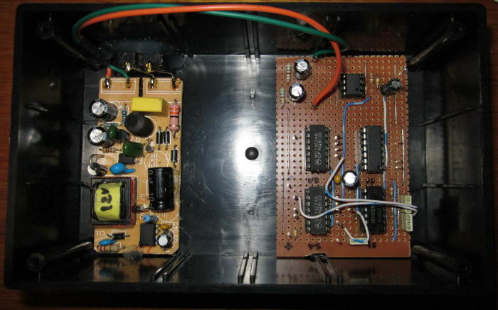
Figure 7 - Power Supply Mounted In Case
The DC connections are double-insulated using heatshrink, and are glued (with hot-melt) into the corner of the case, well away from the mains wires. Note that the two tinned copper wires from the connector to the PCB look like they are touching, but that's due to the camera angle. They are a minimum of 8mm apart at all times.
The other end of the supply PCB is held down with hot-melt. This isn't strictly necessary because it can't move anyway, but I don't like the idea of mains power supplies floating around inside a case. Although this power supply suggestion is applied to P143 here, the same technique can be used for any project that uses a single 12V supply. The SMPS units are inexpensive, and occupy far less space than a transformer, rectifier, filter cap(s) and a regulator.
The next stage is to install a plastic cover over the supply so that nothing can touch any part of it. This is shown in the next photo, but it hasn't been glued down yet.
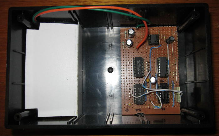
Figure 8 - Power Supply Protective Cover
Hot-melt was used to attach the cover in place, but you can also use silicone sealer/adhesive instead of the hot-melt glue. While many people don't have a high opinion of hot-melt adhesives, they work surprisingly well on ABS (the plastic used for the box) because the surface of the plastic melts a little and this acts as a key to ensure that it sticks very firmly indeed.
The cover is made so that it slides into the guide rails moulded into the inside of the box. Once glued down, the only way to remove the protective cover is to use a scalpel or similar to cut the glue away.
In both the above photos, you can see the Veroboard based version of the project that I built. Initially, I didn't intend to build the whole unit - it was just to test the circuitry to make certain that the project would work as expected. Ultimately, I decided that it was worthwhile, because it provides functions that neither of my other tone burst gates have. One is based on a project published by Electronics Australia in 1979, and that has fixed on/off periods. The other is a Genrad (General Radio) 1396 B, and although supremely versatile, it does not allow a preset off level - it's either fully on or fully off.
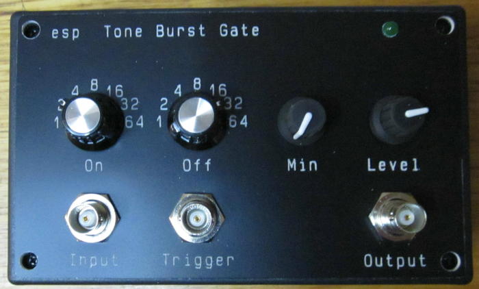
Figure 9 - Completed Tone Burst Generator
Since I have an engraver, I made a quick front panel. It's not the most handsome looking unit around, but it is now a fully functional piece of test gear. You will note that there are no photos of the wiring, because they would be of no use to anyone. I do warn prospective constructors that it's a real pain to wire - especially the rotary switches. I decided to use all available on and off periods, so there are 8 wires to each switch (7 from the dividers and one for the on/off flip-flop (U4A and B).
There are also the input, output, sync and pot wires to be run, as well as the 12V supply. This all amounts to a lot of wires and it's very difficult to keep the wiring neat and tidy. Mine is anything but neat and tidy, but the circuitry is not affected by crosstalk between wires, so while it's a pain to do, I know that it can be done and that it will work provided there are no mistakes.
 Main Index
Projects Index
Main Index
Projects Index