

|
| Elliott Sound Products | Project 137 (Part 3) |
Most of this project is fairly straightforward, although the intending constructor must understand that there is a lot of work involved. As far as I'm aware, this is the only project of its type offered anywhere ... and quite possibly for good reason. If construction is carried out in a disciplined manner and everything is built in the proper sequence, it should all go together painlessly. However, as already noted, it's not cheap to build.
It must be pointed out that the PCBs are double-sided, and like all double-sided PCBs are not forgiving of mistakes. Once parts are soldered into the board, the only way to remove them safely is to cut off the part's legs and remove each lead separately. If you don't, you can easily pull the through-hole plating out of the PCB and damage tracks, and this can render the board useless.
You definitely need a template for the preamp. This is shown below, and if followed exactly the preamp should just drop into place. It's up to the constructor to decide on the type and location of the mic/line switch. The units I built use a slide switch, but these are a nuisance to install because they require a rectangular cutout. It is important that the switch used does not stick out from the panel, as it will be easily damaged in transit.
Although there is provision for a connector for the switch, it's actually easier to wire it directly to the PCB using 1mm tinned copper wire. This makes it easy to remove the preamp with the switch attached.
The chassis is easily made using a 3mm flat aluminium plate, drilled to suit the PCB mounting arrangements. The drawing shows the hole sizes and positions for mounting the preamp. The PCB mount XLR connectors are the only parts that may cause problems, but they can be replaced by conventional chassis mount types, wired directly to the PCB with tinned copper wire. If this is done, some means of mounting the end of the board will be needed - I suggest another bracket as used for the other end. Ensure that the bracket is insulated from the PCB, or you may get excessive buzz due to circulating currents induced into the chassis from the transformer.
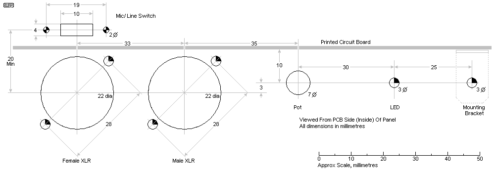
Figure 8 - Preamp Mounting Detail - View From Rear Of Panel
I have shown a 3mm hole for the LED, but this can be increased to 5mm if you wish to use a 5mm LED. The drawing shows a cutout for a miniature slide switch, but this may need to be changed to suit the switch you decide to use. Any SPST (single pole, single throw) switch can be used, but make sure it can't be damaged when the boxes are in transit.
The cutout for a 'push fit' IEC combination socket, fuse and switch needs to be 47 x 29mm. Most of the combination units are designed for a panel thickness of only 1mm, so you must machine the inside of the panel to reduce the thickness or the unit will fall out. Alternatively, you may be able to shorten the securing tabs to allow for the 3mm panel. I recommend that once fitted, the connector should be secured with hot-melt glue or epoxy so that it cannot be pulled free of the panel. If you can get screw-fix types they are much easier to mount, and there is no risk of the connector pulling out. All screws should be sealed with Loctite or similar so they can't vibrate loose.
The combined chassis+heatsink must be as efficient as possible. Although the amp is not especially powerful, it will be used at maximum power for an extended time, and keeping all output devices cool extends their life. There are many possibilities, but the easiest is to use the flat plate for the chassis, and attach a flat-backed heatsink to the outside.
Because the surface area is very large, the thermal resistance between the plate and heatsink will be minimal, however I strongly recommend that heatsink compound is used between the two. Also, make sure that you use enough screws to ensure excellent contact over the whole area. All screw holes must be carefully de-burred, or the burrs will keep the two parts separated - it only needs a tiny air gap to ruin the heat transfer. You will be looking to achieve a minimum of around 0.25°C/W total thermal resistance with free air convection cooling. Assume an average total dissipation of about 100W, and you can expect the heatsink to have a temperature rise of 25°C. Worst case dissipation can reach 120W just for the bridged amp, so don't skimp on the heatsink.
Always remember - there is no such thing as a heatsink that's too big (at least as far as semiconductors are concerned). Your wallet may disagree.
If you make the plate around the same size I used (370 x 160mm), the thermal resistance of just the plate by itself will probably be better than 0.5°C/W, but that's extremely optimistic because it doesn't have the thickness or thermal mass to get rid of the heat from the transistors fast enough, so you must include a finned extrusion on the outside of the plate. If you build the project as powered monitors with a reduced supply voltage, the heatsink and mounting plate can be smaller than suggested here.
Unfortunately, I can't suggest a heatsink, because different types are available in different parts of the world. What I can get easily here is extremely difficult elsewhere and vice versa. One type that is likely to be reasonably common is sometimes referred to as a 'fan' heatsink, or may also be called a 'radial fin' heatsink. Whatever it's called, a 300mm length has a claimed thermal resistance of around 0.7°C/W by itself, so in conjunction with the plate should be acceptable.
Please bear in mind that I can only suggest - it's up to you to determine if the final assembly you come up with is sufficient. For reference, I have included a photo of one of the plates made for the amps I sold, and I know that these have been fine in practice. If you end up with something of similar size, it should also be alright. Note that the plates I had made are intended to seal off a vented box, and are open to the inside of the cabinet. This means that both sides of the plate can act as a heatsink. Do not enclose the back of the amp module, because that severely limits the available cooling.
While it may seem an odd thing to do, you can drill small holes through the plate and heatsink. Although you may imagine that this would cause a lot of air noise, in the context where PA boxes are used it's completely inaudible. What these holes do is create air movement and turbulence around the heatsink, and this can assist with heat removal. I offer this as a comment - it's up to the constructor to try it or not. Do not imagine for an instant that you can use a smaller heatsink though! In case you are wondering, I discovered this with an early prototype.
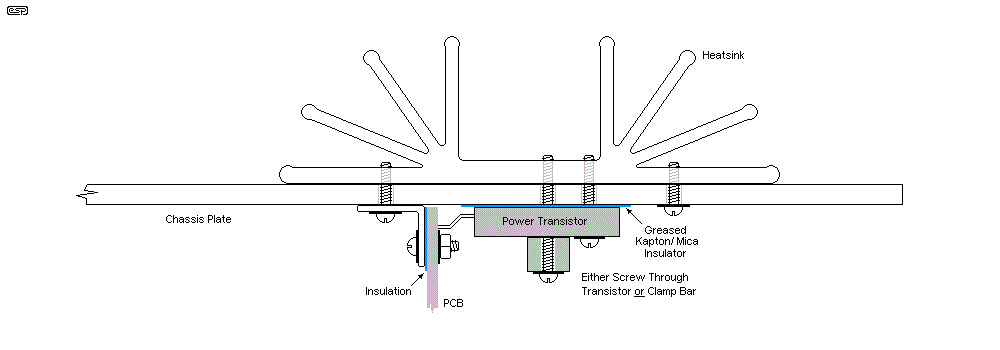
Figure 9 - Mounting Power Transistors & Heatsink To Chassis
If you use the 'fan' type heatsink I referred to earlier, this is how you might mount it to the chassis plate. Make sure the screws are spaced out to allow room for the transistors to mount! You can use two of the screws to attach the power amp brackets as shown. Please note that this drawing is only shown as an example, and is not to scale.
Other styles of heatsink can be used in the same way. You may be able to attach individual 'fins' made from 3mm aluminium angle, but there's a lot of work involved and the end result may not be a success unless you can pack in at least 8 fins, each a minimum of 25mm high and at least 350mm long. The fins have to be close to the power devices or they are useless. This is not an approach I recommend unless you have good metalworking skills and facilities.
Note that the brackets that hold the power amp PCB to the chassis must be insulated from the circuit board, because there is a power supply track under the brackets that can be shorted if you only rely on the solder resist. A thin piece of strong plastic will work, as will TO220 silicone transistor washers (I knew there had to be a use for them). 
Transistors must be mounted using thin mica or Kapton (or aluminium oxide if your budget stretches that far) and heatsink compound. Silicone washers must not be used, as their thermal resistance is much too high. It is extremely important that the thermal resistance between the transistor's heat spreader and the heatsink is as low as possible, and that means that care is needed to ensure that the mounting is as close to perfect as you can get.
Unlike a hi-fi system where full power is rarely used, PA boxes are consistently operated at maximum power for extended periods. This means that there is not only more heat, but it's more or less constant too, unlike a hi-fi where there are loud and soft passages. The limiter helps to maintain the power at or just below clipping, and this can go on all night! Many budget commercial systems seriously underestimate the heat load and I've seen the results - they fail.
When mounting the transistors, consider using a steel clamping bar to hold them down, rather than relying on screws through the mounting holes. 10mm solid square section works well. You may think it's overkill, but really good mounting makes the difference between long term reliability and premature failure. The LM3886 is available in the 'TF' package, which means it is fully insulated. With that package you don't need mica or Kapton, but you still need heatsink compound (thermal grease). If you use the standard version, you need to use an insulator. Again, silicone pads are not good enough.
The following photos show one of the chassis I had made. Please don't ask - they are not available. It is shown as a reference, and so you can see a chassis/ heatsink assembly that is known to work. These measure 370mm long and 160mm wide and were power-coated. Everything mounts onto the back of the panel.
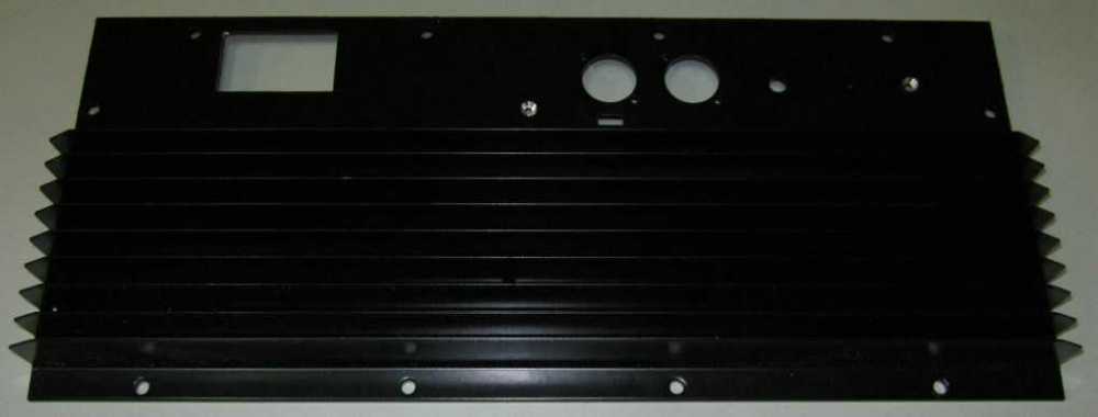
Figure 10 - Chassis, View From Panel Side (No PCBs)
The rear of the panel is shown below, with the three boards mounted in their proper places. The IEC connector isn't glued in and the power transformer hasn't been mounted, and there are no power transistors at this time.
In the photo below, you can see where the 3mm aluminium plate has been machined down to 1mm so the IEC combination socket will lock into place properly (bottom left of the picture). It's unlikely that most constructors will have the necessary tools to do this, and the use of a good quality epoxy is recommended to prevent the socket from being pulled out of the panel.
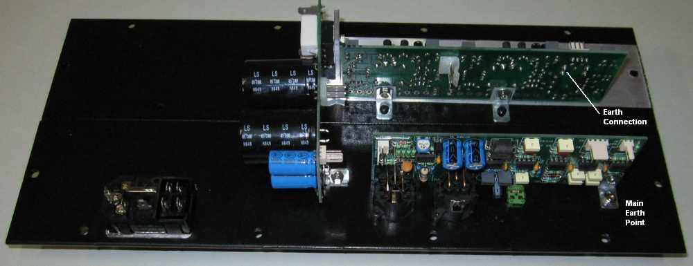
Figure 11 - Chassis, PCBs Installed
Note the locations of the DC connectors on the PSU and power amp boards. They are mounted on the rear (solder side) of the board, which means they must be the installed opposite to the way shown on the silk screen legend. Where the locking tab is shown on the overlay as being at the top edge of the board (for example), when installed on the solder side the tab faces towards the bottom of the board instead. Be very careful to get this right, because the connectors are almost impossible to remove from the board if you get it wrong.
The main earth point shown is important. A heavy gauge earth lead must be run from the earth point near the HF amplifier (the -ve HF speaker terminal) to this screw - held in place by the nut and a washer. If you use a layout similar to that shown you'll find that this is the optimum location for earthing the electronics to the chassis. During prototyping I quickly discovered that earthing at any other (sensible) location caused low-level audible buzz. This is always a risk when you use a horn - because they are so efficient, the slightest noise is immediately elevated to really irritating levels.
Once everything is mounted and tested, I strongly recommend that the filter caps are all stuck together with a liberal amount of hot-melt glue so that the constant vibration doesn't cause leads and/or solder joints to fracture. The toroidal power transformer is located directly behind (i.e. to the left in the photo) the main filter caps, and hot-melt should also be used between the two. You can also use silicone, but it's considerably messier and will make it a lot harder to get the caps off the board again if there is a failure.
Likewise, all cable connectors need to be secure, and this is most easily done using cable ties. Leads from the transformer to the switch must be protected with heatshrink where they solder to the switch and other connectors on the IEC socket. It must be impossible for fingers to make contact with live terminals.
When the quick-connect terminals are attached to the transformer secondary leads, you will almost certainly have to solder them - especially if the lead-out wires are solid core. It is simply impossible to ensure a secure and long-lasting crimp to solid wire unless you use a hydraulic crimping tool, and I wouldn't trust that either. These terminals don't need to be insulated, and the un-insulated types are easy to solder. You will need a fairly powerful soldering iron though, as the wire is quite thick, and able to dissipate a remarkable amount of heat.
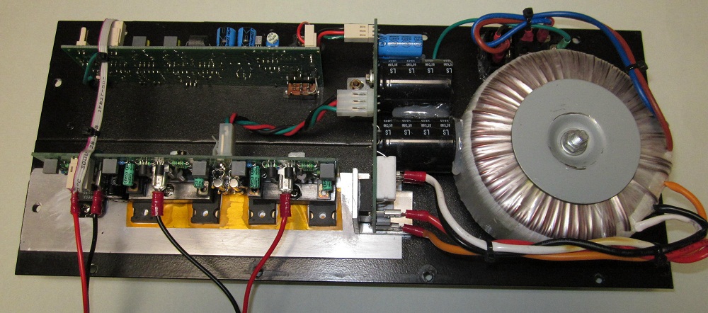
Figure 12 - Completed Chassis, Everything Installed
Full testing procedures are available in the secure section of the ESP site. Never just apply full power to a project such as this - if you made a mistake, the resulting destruction can be very expensive. Each section needs to be checked and tested in a way that is unlikely to damage anything, before full voltage and current are made available. All initial tests on power stages must be done without any speakers connected.
When everything is complete and tested, all screws and nuts should be sealed with Loctite or nail varnish so they can't loosen over time. Bundle any wiring neatly and fasten with cable ties. Make sure that all large parts (especially electrolytic capacitors) are firmly supported with hot-melt glue or similar, and that the power transformer cannot move.
Remember that the minimum nominal speaker impedance for both high and low frequencies is 8 ohms.
 Main Index
 Projects Index