
|
| Elliott Sound Products | Project 130 |
To be perfectly honest, I have no idea why anyone would want an inverse or reverse A-weighting filter. The idea came up though, and it appears that no-one has produced such a beast, especially as a DIY project. It's even conceivable that it doesn't exist at all, which wouldn't surprise me because it does have very limited usefulness.
A-Weighting is traditionally used for all noise measurements, even though it is utterly unsuitable for any noise that has deep bass, is cyclic in nature or has any degree of tonality. Measurements in dBA have been with us for a long time, but far too few people have ever seriously questioned the use of such a radical filter. It turns out that you can add some filtered deep bass that is clearly audible and would be extremely annoying if one were trying to sleep, yet it doesn't register ... at all ... on a sound level meter set to measure dBA (sound pressure level, A-Weighted).
Based on some initial tests I did, further testing was undertaken at a New Zealand university. This backed up my findings completely, and showed that increasing the level of a very irritating modulated bass tone (40Hz) in the midst of band limited white noise didn't show up on the sound level meter. The dB column is an essentially flat reading (no filter), and dBA is the A-Weighted measurement.
| White Noise Plus ... | dB | dBA |
| 40Hz Amplitude Modulated at 0.5Hz, Just Audible | 70.8 | 65.4 |
| 40Hz Amplitude Modulated at 0.5Hz, +10dB | 77.6 | 65.4 |
| 40Hz Amplitude Modulated at 0.5Hz, +15dB | 82.2 | 65.5 |
As you can see from the above, even when the 40Hz modulated tone was increased by 15dB from the 'just audible' level, an A-weighted measurement shown no increase. The tone is very audible above the white noise, and it shows up clearly on a spectrum analyser. The meter says there's nothing at all with A-weighting, but shows a definite increase when set to flat. Can you imagine how annoying it would be if you complained to the 'authorities' about a noise, and some lunatic points to his meter and says "There's nothing there - it's fine, and there's nothing we can do." - even though both of you can hear it plainly. Sadly, exactly this scenario is played out regularly, and wind farms and large industrial plants are a major culprit.
For anyone who doesn't know what an A-Weighting curve is or how it's created, have a look at Project 17. It's alleged that the curve is roughly the inverse of the 30 phon (30dB SPL) curve of the traditional Fletcher-Munson 'equal loudness' curves, but it's arguably actually closer to the 20dB SPL level. This is an unrealistically low sound level, and one that (sadly) very few people will experience for 99% of their lives.
The biggest problem with trying to reverse the filter is the amount of gain needed at low frequencies. A full 50dB of gain is needed at 20Hz, and a lot more at lower frequencies. Frequencies below 20Hz can still be well within the threshold of feeling, even though they are theoretically inaudible.

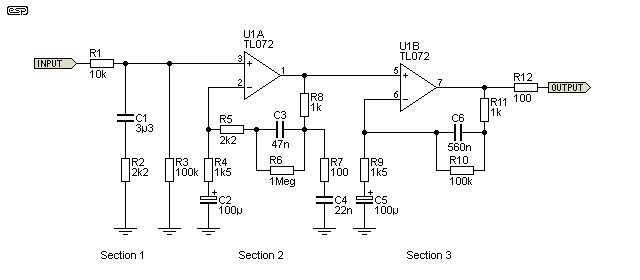
Figure 1 - Schematic Of Reverse A-Weighting Filter
The input signal must be from a low impedance source, because R1, C1 and R2 form the first pole of the filter. The networks around U1A and U1B provide the remainder of the correction. It may be somewhat surprising that considerably more circuitry is needed to reverse the A-Weighting curve than is needed to create it in the first place, but it's all about the gain. 50dB at 20Hz is a gain of 316 - not a major problem in itself, but trying to reverse the passive filter with active circuits is not easy.
It simply cannot be achieved with a single opamp because of the massive phase shift (which would cause a single stage to oscillate), and a passive version can't be used because there would be too much noise in the output signal. The circuit shown will hardly be silent either - some circuit and opamp noise is inevitable with well over 60dB of total gain available.

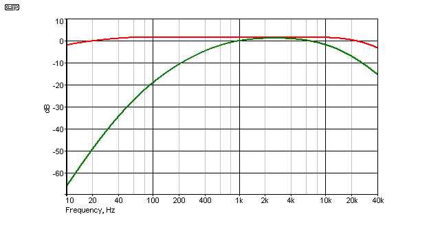
Figure 2 - A-Weighting Curve (Green) And Reversed Response (Red)
The red trace shows the final response, after the input signal has been processed by an A-Weighting filter (green trace). It is not perfect, but is a reasonable compromise across the audio band. Across the range of 50Hz to 10kHz the net response is within less than 0.25dB referenced to 1kHz, and the total frequency response is within +0.25, -1.5dB from 20Hz to 20kHz.

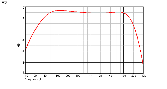
Figure 3 - Error Response, A-Weighted Signal In, Corrected Signal Out
The graph above shows the magnified error, from 10Hz to 40kHz. Over the full range which is more than covers the audio band, the response is -3dB at 11.3Hz and 30kHz. Worst case positive error is +0.23dB at 110Hz and 0.09dB at 7kHz. It is undoubtedly possible to improve on this, but it would be completely pointless. Note too that the circuit has an overall gain of 1.4dB at 1kHz. If you need exact voltages, then this needs to be trimmed out with an output level preset control.
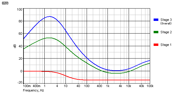
In use, it is vitally important that the input signal applied has already been filtered with an A-Weighted filter. The circuit has a huge amount of low frequency gain (see the graph below), and will distort very easily and at quite low levels if a normal unfiltered full-range audio signal is applied.

Figure 4 - Response Of Each Section Of Filter
Above, you can see the accumulated response at the output of each section (sections are as shown in Figure 1). The extreme low frequency gain is very high, so the circuit will take a little while to settle after power is applied or an overload. Note that this graph extends from 0.1Hz (100mHz) to 100kHz. The gain peak is at 1.8Hz, and although it might look excessive it's all needed to get the response shown above. To get flat response down to 10Hz would require even more gain, with the real risk of low frequency oscillation (which is still possible if wiring is incorrectly laid out).
Stage 3 response is the cumulative frequency response of all three stages. Stage 2 actually has the highest gain (around 500 at 1.8Hz). It also has the modest high frequency boost that's needed to counteract the HF rolloff produced by the A-Weighting filter. The expected gain from each stage is well within the normal capabilities of most common opamps, such as the TL072, NE5532 or 4558.
Much as I'd like to be able to offer a PCB which would make construction trivial, this won't happen. My guess is that engineers across the whole planet will build somewhere between none and 10 of these filters, so a PCB is not warranted. Veroboard or other prototype board will work fine though, although good layout practice will be needed to prevent noise pickup and/ or oscillation. Once the first filter stage (R1, C1 and R2) is out of the equation, the active circuitry has a minimum gain of 5.8 times at 2.4kHz.
Gain at 1.8Hz is at least 25,000 (88dB) and may be much higher... up to about 94dB - a gain of over 50,000 - depending on opamp low frequency open-loop gain. This high gain is necessary to counteract the astonishingly large attenuation of the A-weighting filter at very low frequencies. Power supplies must be well bypassed and very low impedance at low frequencies to prevent low frequency instability (motor-boating). High frequency gain is reasonably tame, and (assuming ideal opamps) can only achieve a gain of about 46 (33dB) at 1MHz. In reality it will be less than this because of the opamp's frequency compensation.
Component values are fairly critical, so resistors and capacitors (with the exception of C2 and C5) must be within 1% tolerance. It's a lot cheaper to buy normal caps and select them than to purchase 1% versions, as they are normally prohibitively expensive.
Note that power supply pins are not shown in Figure 1. The supplies are shown in the opamp diagram below, and supply voltage will normally range from about ±12V to ±15V.
 | The standard pinout for a dual opamp is shown on the left. If the opamp is installed backwards, it will almost certainly fail, so be careful. The suggested TL072 opamp will be quite satisfactory for most work, but if you prefer to use ultra low noise devices, that choice is yours. Because of the circuit topology, there is no real need for extremely high input impedance, and the 4558 is an economical choice. The NE5532 is potentially a good choice for low noise applications. You can probably use the LM833 too, but it's one of my least favourite opamps (the reason you don't see it in any of my projects). |
After the circuit is built, connect to a suitable power supply - remember that the supply earth (ground) must be connected! When powering up for the first time, use 100 ohm 'safety' resistors in series with each supply to limit the current in case you have made a mistake in the wiring. Because these resistors will increase the power supply impedance (especially at low frequencies), don't be alarmed if the filter starts to oscillate. This just means that the circuit is working, so the 100 ohm resistors can be removed and the circuit is ready for use.
Note that this circuit is theoretical, is provided as-is, and has been simulated using exact value components. While every care is taken, errors or omissions may be found that may affect the ability of the circuit to function as described. ESP provides this schematic and graphs for information only, and there is no warranty of any kind. You build the circuit entirely at your own risk, and ESP accepts no responsibility for failure of the project to perform as expected.
 Main Index
 Projects Index