
|
|
| Elliott Sound Products | Project 128 |
Meter bridges are not as common as they once were, but are still an invaluable tool for any serious recording work. The analogue VU meter using a moving coil movement is still a commonly used meter, and even though true VU (Volume Unit) meters with calibrated ballistics (a measure of the needle's response to transients) are extremely expensive, comparatively cheap meters are still useful once you get used to them. The greatest advantage of an analogue meter is that it provides a good indication of the average level. Peaks can be monitored with LED meters or PC based recorders, but the average level is what your listeners will ultimately hear. Personally, I really dislike LED 'VU' meters for recording, and provided there is a peak clip LED somewhere that lets me know when I'm running out of headroom I far prefer an moving coil analogue meter.
Apart from anything else, the mechanical movement VU meter has a nice retro look to it that many people enjoy. The meter face can be backlit using LEDs of any colour you choose. A series string of 4 LEDs along with a series resistor to limit the LED current to no more than 10mA should work nicely.
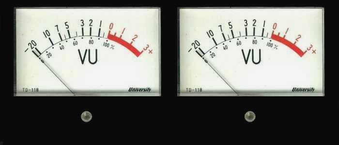
Figure 1 - Typical Stereo VU Meters
A high resolution image of the complete meter face is available. This has been cleaned up and enhanced to improve the saturation of the red section of the scale. Feel free to download it and resize to suit the movements you wish to use. To view or download the image, click here. Be warned that the image is fairly large (about 185KB, 2667 x 2343 pixels).
While some users may simply connect a VU meter directly across the output signal lines from the mixer, this approach will cause extra loading on the signal, which is non-linear. While the distortion introduced might not be high (it depends a lot on the output impedance of the mixer), it is definitely measurable. The extra load may also reduce headroom, because the output stages may clip earlier than expected due to the additional load. The meters shown above are quite sensitive (100µA DC full scale), but still cause over 0.3% distortion when connected to a 600 ohm source. Distortion is worst at around mid-scale - right where it will sit for much of the time with typical programme material. The nominal impedance for a "true" VU meter is 3,900 ohms - the resistor can be seen in Figure 2.
This project is designed to be used with either balanced or unbalanced analogue signal transfer, and uses the Project 87A dual balanced receiver PCB. Since most VU meters have a simple rectifier built-in, no rectifier is used. The circuitry is designed to provide the absolute minimum of loading on the signal, and it completely isolates the rectifier in the meter from the audio line, avoiding distortion and/or signal loss.
The nominal signal level that corresponds to 0VU is +4dBm (1.228V RMS), however this is not always available. Especially with computer sound cards, at that voltage there may be almost zero headroom, so the gain of the circuit should be adjusted to suit your setup. If used with a mixer, it may be necessary to reduce the output level of the board with a resistor in series with the meter. This is explained in more detail below.
Note that VU meters do not read the RMS voltage, they read the average of the rectified signal. This is also true of nearly all cheap multimeters, analogue and digital. In the case of multimeters, the scale is calibrated in RMS, but cannot give an accurate RMS reading. For VU meters, this is not really a problem because you quickly get used to the way the meter responds and can make the necessary mental adjustment, however it is important that the user understands that a VU meter does not provide an RMS reading.
At one stage, large mixing consoles had a full width meter bridge mounted along the back of the console. While some early mixers provided a meter for each individual channel, this became impractical as mixers gained more and more channels. It is still common to have one or two meters that can be switched to monitor various inputs and outputs, including the PFL (pre-fade listen) function.
The project shown here is not intended for this type of application. Instead, the output signal to the FOH (front-of-house), recording outputs or foldback system is routed through the meter bridge using XLR connectors. Other connections can also be used, including mini stereo jacks, although these do not qualify as a secure or reliable audio interconnection.

Figure 2 - Insides Of Meter Shown In Figure 1
Figure 2 shows the internals of a reasonably typical VU meter. A pair of these meters are shown in Figure 1 as a general concept for a cased meter bridge as described here. The holes below the meters in Figure 1 are to allow access to the mechanical zero adjustment which moves the slotted bar just below the centre of the movement itself. This moves one end of the hairspring that is used to return the meter to zero. There is another at the rear of the moving coil assembly, and these springs serve the secondary purpose of supplying DC to the coil itself.
The rectifier is also visible (the reddish coloured thing with a resistor and three leads coming from it). The resistor reduces the sensitivity so that a voltage of about 1V gives full scale deflection. This gives enough range to allow the meter to be calibrated externally. It's worth noting that without a small modification, a meter such as this is next to useless. This is because the ballistics are completely wrong, and there is massive over and under-shoot. A VU meter is designed to have a relatively slow response. It is driven from a full-wave averaging circuit defined to reach 99% full-scale deflection in 300ms and overshoot not less than 1% and not more than 1.5%. Without modification, few standard meters (despite showing VU on the front) come even close to this requirement.
The one shown has around 20% overshoot, which is to say that if a 0VU signal is applied, the pointer will swing up to about +2VU, drop below 0VU and jiggle around for a while before showing the proper reading. Ideally, the ballistics should be controlled with an active circuit, but simply adding a capacitor will get you close enough for all but the most exacting requirements. For this particular movement, a 33µF 16V capacitor is about right, although the movement is still somewhat under-damped (I would prefer to use a 47µF cap with this movement). Addition of a capacitor will also slightly increase the loading (and distortion) if the meter is connected directly across signal lines. Early VU meters used internal (mechanical and/or electro-mechanical) damping that was adjusted to ensure the meter reacted properly, but attempting to add mechanical damping is far too difficult with modern (cheap) meter movements.
A pair (or several pairs) of meters can be mounted in a suitable enclosure, and the signal routed through the meter bridge. The impedance of the balanced receiver is deliberately very high (100k) to ensure that there is the lowest possible disturbance to the impedance on each signal line. The schematic for the PCB (one channel only) is shown below.
The meter amplifiers are based on the P87A balanced receiver, and PCBs are available. There are some differences between this and the normal wiring scheme for P87A, the primary change being to increase the value of R102 (202) and R109 (209). This is done to ensure that your signal lines are not loaded, and also that the common-mode rejection ratio (CMRR) of your balanced lines is not compromised. If FET input opamps are used, these resistors can be increased to 1M. In all cases, they should be at least 1% tolerance or better. Multimeter selection will allow you to get them to within a few ohms of each other. The exact value is unimportant, but matching is critical.
Figure 3 - Schematic of Modified P87A Balanced Receiver
The second channel uses resistors R201, R202, etc. R105 can be selected for a specific gain, or ideally leads will be run from the PCB to a calibration pot accessible from outside the enclosure (with a screwdriver). This allows you to set the gain of the meters so that a known audio level (+4dBm or 1.228V for example) to show 0VU. This allows you to have an absolute reference, and a calibration tone can be used to ensure that the meters and everything beyond (power amplifiers, recording system, etc.) are set correctly.
After you get used to having meters that show you the levels, it becomes second nature to glance at the meters at regular intervals, and know exactly how loud the PA system is, or that the average level being recorded is correct. You must be aware that a VU meter is utterly useless if you need to monitor peak levels - it is used to allow the engineer to know at a glance what the average level is, as this determines how loud the signal sounds to others.
The most difficult part of the construction will always be the enclosure. Large holes must be cut for the meters, and you need to mount a male and female XLR connector for each channel. You will also need a power supply (I suggest Project 05) and a suitable transformer. The latter may be external if you wish.
Once the mechanical side is worked out, build the balanced receivers, which are also the meter drive amplifiers. The basic wiring scheme is shown below. In order to prevent the meter bridge from injecting any noise into the signal lead shields, pin 1 of the XLR connectors should be wired as shown. The 100 ohm resistor gives the meter amp circuit a ground reference without the chance of injecting noise into the cable shield. The resistors marked S.O.T. (select on test) may not be needed, depending on the sensitivity of your meter.
Make certain that the P87A output does not clip if you run a high level signal.
The P87A board does have some gain, and if you normally run a fairly high level the output from the PCB will need to be reduced. The resistors should be chosen so the calibration trimpot has some range above and below the desired setting.
Figure 4 - Overall Wiring Scheme For Meter Bridge
The wiring is quite straightforward and should present no problems. The resistors marked * are optional. These should be added is the P87A board clips the signal even at the lowest gain setting. Assuming that the resistors R102/109 (and of course R202/209) are 100k, using 100k resistors in series with the inputs will reduce the gain by 6dB. Feel free to use the value that gives you the best range for the calibration control. These resistors don't need to be an exact value, but it is important that they are well matched (as described above) so the line balance impedance is not affected.
These days it can be difficult to find meters calibrated in VU, and those you do find may not have an inbuilt rectifier. If this is the case, you will need to print calibrated scales to attach to the meter face, and you'll also have to wire up a bridge rectifier using germanium diodes. Normal silicon diodes will function, but the meter calibration will be hopelessly wrong. Early VU meters (they were invented about 90 years ago at the time of writing) used copper oxide or selenium rectifiers which have a relatively low forward voltage. This is why the meter scale starts at -20VU - the rectifier didn't start to conduct at lower signal levels. Germanium diodes give an acceptable approximation to the original rectifiers. The meter movement needs to be reasonably sensitive - 100µA for full scale should be about right.
Figure 5 - Adding A Germanium Diode Bridge Rectifier & Capacitor
If you cannot get a proper VU meter, you may need to use a standard movement (50 or 100µA DC), and add VU meter scale (see above for a link to an image I created for just that), and a germanium diode bridge along with a capacitor to enable the meter to be driven with AC (as well as have the proper ballistics). If you take the movement apart, be very careful - the moving coil assembly is delicate and easily damaged. Because there's a strong magnet in the meter, make sure that no iron filings or other magnetic particles are anywhere near the disassembled movement. Once they get inside it is virtually impossible to remove them!
The diode bridge is easy (any germanium small signal diode can be used - OA91, OA95, 1N60, 1N34A etc. or you can try BAT43 Schottky diodes), but the capacitor will be trial and error. Different movements have differing degrees of mechanical or electromechanical damping, some have virtually none at all. It's much easier to experiment with the proper value of capacitor if the rectifier is not inside the meter case, but if the rectifier is inside you'll need to do some careful tests and modifications to determine the correct capacitance then add the capacitor. Naturally, if you only wish to use the meters as 'eye candy' then you don't need to bother, but it seems a shame to waste a perfectly good pair of meters. A typical 100µA movement will have a resistance of about 4kΩ, although this does vary.
Rather than use a full power supply (such as P05), the circuit will run happily from a simple dual supply using a bridge rectifier, filter caps and resistors and zeners to set the correct voltage. While far from elegant, a simple supply will work just fine. It may even be possible to tap into the mixer's power supply, and the extra few milliamps is unlikely to cause any stress. Make sure that the earth (ground) is also carried through - you must use the 3 wires ... +ve, -ve and GND.
Depending on the opamps used, the current demand of the board is quite modest. Suitable opamps include TL072, RC4558 or even LM358, although the latter have limited output current. Allow about 5mA for each dual opamp, or 10mA for the board.
Connect the balanced receiver board to a suitable power supply - remember that the supply earth (ground) must be connected! When powering up for the first time, use 100 ohm "safety" resistors in series with each supply to limit the current if you have made a mistake in the wiring. Do not connect the meter until you are sure that the PCB is working properly, as it may be damaged! As noted above, P05 is suggested as a power supply, and although it's far better than you need for this application, it's easy to build if the PCB is used.
With power applied, check that all opamp pins except 5 and 8 are at or near zero volts. Pin 5 should measure at least -12V and pin 8 +12V with the 100 ohm safety resistors installed, and a ±15V supply. If any voltage is wildly different, you have made a mistake that must be corrected before you continue.
Once the voltages are correct, you may then wire in the meters and apply a signal. The test signal does not need to be balanced - single-ended signal will work just fine, but the meters will only read half the normal voltage. Once the meters are giving a sensible reading, you can finalise the values for the S.O.T. resistors and you are ready to go. Remember to check the PCB outputs with an oscilloscope to ensure that there is no clipping at any level within the meter's range. Clipping won't affect your signal, but it will affect the meter reading.
 Main Index
Projects Index
Main Index
Projects Index