
|
|
| Elliott Sound Products | Project 123 |
 PCBs (P09 Revision C) are available for this project. Click the image for details. (See Also Project 81 for details of the 12dB/octave version).
The Linkwitz-Riley crossover is one of the most popular topologies these days, and there is no doubt that is well behaved, and provides excellent performance. It also has very good driver protection, because the roll-off is very fast. However, it is this fast rolloff that makes some people rather wary - after all, a fast rolloff also means an equally fast phase shift. In many cases, an 18dB/octave filter may just fit the bill perfectly. It has a better rolloff characteristic than a 12dB filter, but is less radical than 24dB types. At the crossover frequency, both the high and low pass sections are -3dB, not -6dB as with the Linkwitz-Riley configuration. Odd order crossovers still sum flat, because there is a 90° phase shift between the two outputs that removes the peak that would otherwise be created. It is worth noting that the tweeter (in particular) will have 3dB more power at the crossover frequency than with a 24dB/ octave L-R design, and this must be considered if you try to push the xover frequency too low.
Note that opamps are shown as TL072s, but you can use any opamp you prefer. They are not critical, but use of low noise types is recommended.
The Project 09 Circuit boards are easily adapted for use with this project. It involves nothing more complex than changing a few parts, and re-calculating the values for the crossover frequency required. Since the PCB wasn't designed for this, there is a bit of messing around, but it's not that great.
The modified 18dB filter is shown in Figure 1. Because the second opamp is configured to have a gain of two, this has the major advantage of using identical resistor and capacitor values. There is an inherent gain of 2 (6dB) for each output, but this will rarely be a problem. It is normal to provide trimpots for setting the output levels for the high and low pass sections, so the gain is easily removed. Where cost is critical or minimum size is desirable, the version shown in Figure 1 is ideal. The circuit as shown produces an absolutely flat summed output, with no peaks or dips.
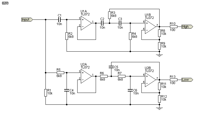
Figure 1 - 3rd Order High & Low Pass Filters
Above, the complete 2-way crossover is shown, and using 10nF caps and 6.8k resistors has a crossover frequency of 2.34kHz. Note that the values are exactly the same for both high and low pass filters. The formulae are provided below, and again, these are simplified to make it simpler to determine the correct values for your application. Wherever possible, I suggest that caps be no less than 2.2nF, and resistors should be no less than around 4.7k to minimise opamp loading. The maximum resistance should be ideally kept below 100k for minimum noise. You may choose the resistance or capacitance first, then calculate the other. Use the table below to select a reasonable starting value.
Crossover Frequency ...
C1 = C2 = C3 = 1 / ( 2π × f × R ) ... or
R2 = R3 = R4 = 1 / ( 2π × f × C )
(Where R and C are the basic frequency determining components.)
As is typical with odd-order crossovers, the two outputs are 90° out of phase at all frequencies. At any frequency far enough away from the crossover, this is immaterial. The slope is 60dB/ decade across the stop band as is expected from an 18dB/ octave filter.
Note that in each circuit shown here, R1 is used to ensure there is a DC part to earth. Without this, the low-pass filter has no earth reference voltage, so will swing to one or the other supply rail. It may be omitted if the crossover is connected directly to another opamp (such as an input buffer, or balanced to unbalanced input stage). The 100 ohm output resistors must not be omitted, as many opamps will oscillate when directly connected to a shielded (coaxial) cable because of the cable's capacitance.
For your convenience, I have included the following table that covers some common crossover frequencies. There are many, many more combinations, but the calculation is not at all difficult so it's easy to work out the values yourself if the table doesn't include your preferred crossover frequency.
| Frequency | Resistance | Capacitance | Frequency | Resistance | Capacitance |
| 72 Hz | 22 k | 100 nF | 603 Hz | 22 k | 12 nF |
| 88 Hz | 18 k | 100 nF | 737 Hz | 18k | 12 nF |
| 106 Hz | 15 k | 100 nF | 884 Hz | 15 k | 12 nF |
| 133 Hz | 12 k | 100nF | 1.105 kHz | 12 k | 12 nF |
| 159 Hz | 10k | 100nF | 1.326 kHz | 10 k | 12 nF |
| 219 Hz | 22 k | 33 nF | 1.592 kHz | 10 k | 10 nF |
| 268 Hz | 18 k | 33 nF | 1.941 kHz | 8.2 k | 10 nF |
| 322 Hz | 15 k | 33 nF | 2.341 kHz | 6.8 k | 10 nF |
| 402 Hz | 12 k | 33 nF | 2.842 kHz | 5.6 k | 10 nF |
| 482 Hz | 10 k | 33 nF | 3.386 kHz | 4.7 k | 10 nF |
All the values shown above are very opamp friendly, and will not cause any significant output loading which can result in increased distortion. Likewise, the values are all consistent with low noise, since resistor values never exceed 22k. There are countless other combinations of course, some of which will be very close to the examples shown, while others will give in-between frequencies.
If the P09 PCB is used, the values of R3, R4 and C5, C6 need to be re-calculated, because the option of using the opamps with gain is not provided. This should cause no great hardship. It may not look like it at first glance, but the P09 board is so easy to adapt that I should have thought of doing so earlier. It's also possible to make the crossover asymmetrical (e.g. tweeter uses 24dB/ octave, with 18dB/ octave for the midrange). There's no real advantage to doing so, but some people seem to like asymmetrical crossovers.
The values for R3, R4 and C5, C6 are 'interesting'. R3 has to be half the value of R2, and R6 is twice the value. Likewise, C6 is half the value of C4, and C6 is double the value. The resistors and caps have a 4:1 ratio. This is necessary to increase the Q of the second filter to obtain a Butterworth response. This isn't particularly easy to achieve, but it is possible to get pretty close.
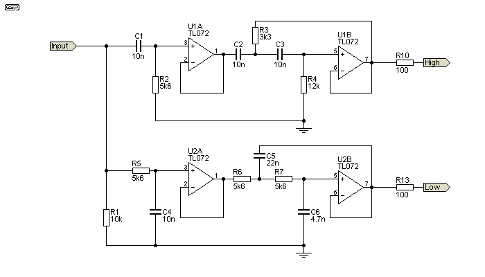
Figure 1a - 3rd Order High & Low Pass Filters (Unity Gain)
The circuit shown above has a frequency of 2.85kHz, and has a small (less than 0.5dB) dip near the crossover frequency. Arranging the optimal 5nF, 20nF capacitors and 2.8k, 11.2k resistors is a bit awkward, but it can be done with a little trickery (e.g. 2 × 10nF in series to get 5nF, and two in parallel to get 20nF). It is possible to fit this onto the P09 board, albeit by adding a cap on the underside of the PCB. If you use 22nF for C5 and 4.7nF for C6 (as shown) you get a small dip at the crossover frequency. The resistors are then 3.3k and 12k (R3, R4). Very few speakers will be that good, so the error is probably inconsequential in most systems.
For a 300Hz filter, you only need to increase the capacitor values by a factor of 10. Other frequencies can be calculated easily enough, and since resistor ratios are fairly consistent, most will cause few problems. For example, if you wanted an 800Hz crossover frequency, you'd double the nominal capacitance (22nF), and calculate that the resistors need to be 10k (the actual frequency will be 723Hz). The other caps will be 47nF and 10nF (C5, C6 respectively), and the resistors 4.7k and 22k (R3, R4 respectively).
This isn't quite a friendly as using the filter opamps with a gain of two, but it does let you use the P09 board quite easily, and get very good results without having to use 'exotic' component values.
The traditional 18dB Sallen-Key unity gain filter is shown in Figure 2. This has the distinct disadvantage of requiring often impossible resistor and capacitor values, and input impedance is often much lower than may be desirable. To illustrate this point, the filter shown below has an input impedance of less than 400 ohms at 10kHz, and it's still only 850 ohms at 1kHz. Input impedance doesn't exceed my suggested minimum of 2.2k until the frequency has dropped below 350Hz. Few (if any) normal signal sources will be able to drive such a low impedance without either excessive distortion and/or a severe reduction in the signal level (typically less than 1V RMS at any frequency). When used as a crossover, the source must drive the two filters, and the low impedance at high frequencies is especially troublesome for most opamps.
Even within a purpose-built unit this is unacceptable, because few opamps can drive such a low impedance at more than a volt or so (RMS). The loading also increases distortion well before the opamp clips. While resistances can be increased and capacitors reduced accordingly, this may increase noise - especially if the opamps use bipolar transistor inputs (e.g. NE5532). Resistance will become very high indeed for a low frequency crossover network, otherwise the capacitance values will be very large.
While odd values can be created by using series and parallel networks as required, this adds to the component cost and, more importantly, makes the board bigger and increases the chance of errors. Where cost is critical or minimum size is desirable, the alternate version shown in Figure 1 should be used. While it does use an extra opamp, the extra cost is negligible and performance is improved. The 'traditional' filter also (usually) has a small dip in the summed response (around 0.5dB) because the alignment is not quite perfect. This is due to the fact that the output impedance of the first filter section is non-zero, so the following filter is affected, and also loads the first - the effect is therefore compounded.
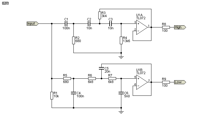
Figure 2 - 'Traditional' 3rd Order Crossover
Although the same basic formula used for the modified version applies, you can see from the above that ...
R2 = R / 10, R3 = R / 2 and R4 = R × 2 and ...
C1 = C4 = C × 10, C5 = C × 2, C6 = C / 2
(Where R and C are the basic frequency determining components.)
The response dip and low input impedance can both be resolved by adding a buffer after the first filter stage as shown in Figure 1. C1, R2 and R5, C4 are then restored to the same value as the tuning frequency dictates (in this case, 6.8k and 10nF). You still have the disadvantage that you need R and C × 2 and R and C / 2 values. Using the nearest E12 series parts may not give an acceptable response across the crossover frequency. However in the above example, making R3 = 3.3k, R4 = 12k, C5 = 22nF and C6 = 4.7nF gives very good results. As noted above, this is taken care of with the P09 board.
For the circuit as shown, the maximum deviation from flat response is less than 0.2dB using these values, but you can't guarantee that this will always be the case. Some combinations of values simply won't provide a satisfactory 'fit' to the filters - especially for the capacitors, which are generally only available in the E12 series.
Finally, we can have a look at an arrangement that initially looks as if it can't work very well at all. By modifying the first filter (passive) section to present a higher impedance to the signal source, the filter becomes usable without risk of overloading the source opamp. Doing so increases the impedance to the second (active) section, so there are compromises.
Note the comments above about the second filter loading the first and having a non-zero input impedance to see what I mean. So, if the (passive) input filter uses the same values as the active filter, we should expect that the end result will be pretty poor, but it's somewhat better than one might imagine. The schematic is shown below, and it really is the simplest 18dB crossover ever. It's not precision, but for a 'quick and dirty' network suitable for basic sound reinforcement or perhaps an active surround speaker, it should do quite nicely.
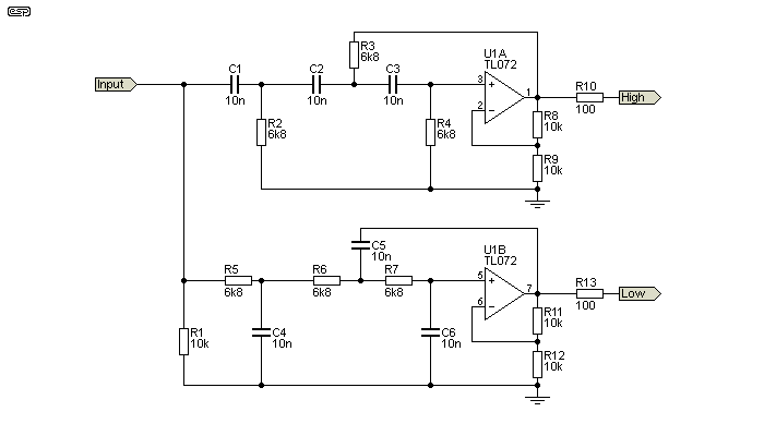
Figure 3 - Simplest Possible 3rd Order Crossover
The same frequency formulae apply as for those above, but to find out just how much of a compromise we have introduced, it's necessary to show the response curves. Although you can't measure the exact deviations from flat response on the graph below, the peaks on either side of the xover frequency are +0.9dB, and the dip at crossover is -1.9dB (assuming exact values for all caps and resistors). At the crossover frequency, each output is -7dB with respect to the level at a couple of octaves either side of the crossover. While this might seem rather odd, that's just the way it works out.
In addition, each filter has a 1dB peak just before rolloff. While not exactly perfect, it is unreasonable to expect many budget loudspeaker drivers to come even close to this degree of flatness. Overall, this is absolutely the easiest and cheapest way to build an 18dB/ octave active filter, yet it can give results that are surprisingly good for such a simple arrangement.
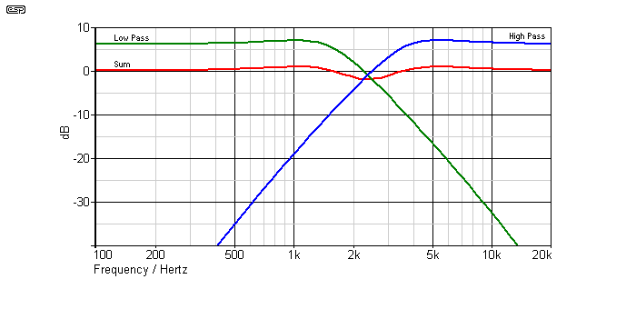
Figure 4 - Simplest Possible 3rd Order Crossover Response
Note that the (electrical) sum of the two outputs is shown displaced by 6dB for clarity. You can see the peaks on each filter, and the slight 'wobble' in the summed response. There are a great many high-priced loudspeakers that do a lot worse, and the major artifact is a very broad dip - dips are far less audible than peaks, and you might not even pick it in a double-blind test. Naturally, the actual drivers used will either make the overall response better or worse, depending on their behaviour at the crossover frequency.
It is important to point out that the 'simplest possible' circuit only works as described if the opamps are designed to have a gain of 6dB. If you try it with the traditional filter topology, performance is a great deal worse, having a very pronounced dip of about 4dB at the crossover frequency, rather than a gentle 'wobble'.
For serious applications, the Figure 1 circuit is close to perfect. While it does exhibit some component sensitivity, it's no better or worse in this respect than any other filter type. As a nice compromise between the (comparatively) very slow rolloff of a 12dB filter and the (also comparatively) radical slope of a 24dB Linkwitz-Riley crossover it's hard to beat. By eliminating all odd values, component matching is a lot easier if you choose to do so, and there is no requirement for series and parallel components to get the exact values you need. The gain of two (6dB) is easily removed with a voltage divider if necessary, but since most people will use pots or trimpots to set the output levels anyway, this minor objection is of no consequence.
There really isn't a lot to recommend the traditional approach, since it requires odd values and has an input impedance that is generally too low to be easily driven by most opamps. If the passive input filter section is made using higher values, then the active section will end up using values that are too high and may cause noise problems.
There are other ways to achieve an 18dB/ octave filter using identical frequency-determining components and three opamps. I've not included the design here as it has no significant advantages over the other approaches, but uses more opamps. Some will see that as a disadvantage, while others don't care one way or the other.
 Main Index
Projects Index
Main Index
Projects Index