

|
| Elliott Sound Products | Project 110 |
 Please Note: Short-Form kits are now available for this project. Click the PCB image for details.
After much haranguing from readers of these pages (and considerable Web searching for something suitable which turned out to be fruitless after a couple of false starts), a remote control is finally a reality. There are quite a few remote control ICs available, but virtually none that can be purchased in hobbyist quantities. This means that the devices would have to be purchased in bulk, but even there, few companies are willing to supply in less than 1,000 quantities. That is a big stock inventory to have to keep, and both the transmitter and receiver are required. After a lot of soul searching, I finally had to take the plunge and look at using a programmable microcontroller (PIC) to do the job. This turned out to be easier than I first thought, and some clever features in the one selected certainly helped.
This is a true 'minimalist' remote, having but three functions ...
Volume Up, Volume Down and Mute
Volume is controlled by a motorised (motorized for US readers) pot rather than any of the 'digital' pots that now abound, and this was done for a number of very good reasons.
While it is hard to claim that the latest digital pots are of inferior performance, they are not readily available - nor are motorised pots for that matter, but you can still get them without too much stress (a Web search will turn up quite a few suppliers). The advantages of the motorised pot is that it requires no backup to maintain the last setting, uses a simple knob for manual override, and they do look really cool.  In addition, the knob provides a display of the current setting, eliminating the requirement for a display device to show the volume. This simple task is more complex than it may seem, and making it look good is (or can be) very difficult.
Likewise, the choice of a relay for muting may seem a bit archaic in this day and age, but relays have the great benefits of being extremely reliable (10 million mechanical operations is typical), low cost, and easy to get. You might think that the 'hard' mute by a relay will sound unpleasant, but in my system it simply sounds like what it is - an instantaneous silence/signal. It is imperative that the preamp has zero DC output though, or you will hear a (potentially) pronounced click through the speakers. Although contact 'bounce' is very visible on an oscilloscope with a sinewave (it's audible too), it does not cause a problem with programme material.
The remote transmitter and receiver are based on the 12F683 (8 pin) device, and so far have proven themselves to operate very reliably.
 | If you happen to have Sony equipment (especially a Sony TV) the remote will almost certainly cause you some grief, since it uses
the Sony SIRC protocol. I suggest that owners of such equipment not use the ESP remote to prevent interference between devices. Please be aware that correspondence indicates that some universal remotes may have difficulties with the receiver. At this stage, there does not appear to be a definitive resolution. It is possible that 'teaching' the remote with an ESP transmitter may work, but this has not been verified. |
I have been advised that Sony 'Device 1' (TV) is the correct match for the receiver. The codes are on the numeric keypad but can be reassigned if you have a universal remote ...
2 / 3 Volume Up
3 / 4 Volume Down
4 / 5 Mute
Thanks to Ian M for the details. Note that this is provided in good faith, but has not been tested by ESP. The actual button may be different for different Sony remotes. The second set of numbers refer to the Sony RM-VLZ620 remote.
The photos below show the transmitter, and the receiver below, and are about 30% over full size (depending on your screen resolution). The receiver has two sets of holes for the IR receiver IC, so that it may be mounted end or side to the front panel. As can be seen, there is no heatsink on the regulator, and even with a 20V DC supply it doesn't even get warm during normal use.
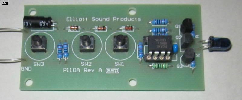
Transmitter - P110AS
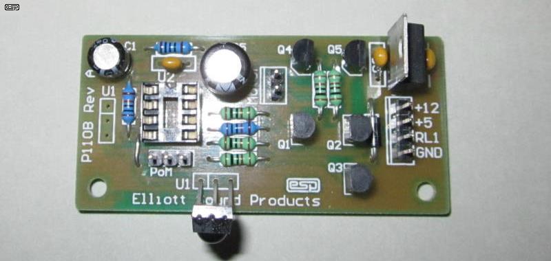
Remote Receiver - P110B (No PIC or Mute Jumper Installed)

An Example Transmitter Housing
The above photo shows my second attempt at a suitable housing. The first is perfectly functional, but is big and chunky (using an off-the-shelf remote housing). There is a considerable amount of work involved and they would be very expensive to make. However, the photo may inspire others to make an exceptionally handsome remote  .
.
In case you were wondering, the case shown is made from a length of aluminium bar plus some 3mm sheet for the back, and the inside was milled out to take the PCB and batteries. The inlaid engraved panel sets it off nicely. The buttons were turned from aluminium rod, and just sit on top of the small switches. The transmitter PCB is a prototype of those in the photo above.
While it would have been possible to have a remote with a myriad of buttons like those typically offered these days, it was felt that this would have been rather pointless. Complexity (and cost) is increased, you need to have a keypad rather than simple push-buttons, and the nice little PIC that I used would have to upgraded to something with more inputs and outputs. The ability to switch sources is marginally useful (use the mute output for that instead if it is so important to you - I may add details on how to do this if there is any interest), but for the most part, there is not all that much you can do from the lounge chair. I am always amused by remotes for VCRs and CD/DVD players that offer an eject facility. So you press the button, and then ... have to get up anyway!
There are (naturally enough) two parts to the design, as described below ...
Transmitter
The transmitter is shown in Figure 1, and although straightforward, there are a couple of tricks that I had to incorporate to minimise battery drain during standby. Although the PIC quiescent current is only 200uA, that will still flatten a pair of AA or AAA 1.5V cells over time. To get around this, when a button is pressed, it gates on Q1 and hence Q2, and applies the supply to the PIC. C2 maintains power for a short period after the button is released, although this is only important for the mute control. It can be omitted, but I don't recommend that you do.
You may well ask "Why not use diodes?" Good question. Because the minimum voltage for the PIC is around 2V, diodes would reduce the available 3V too much (even Schottky diodes will reduce the supply by well over 100mV), whereas the arrangement shown loses only around 30 millivolts when activated. This means maximum battery life, and rechargeable cells can even be used. Standby current with the circuit shown is essentially zero - there may be a few nanoamps of transistor leakage, but it will be almost impossible to measure. Initial tests put the leakage at an unmeasurable current (the emitter to base resistors are essential for minimum leakage). The cost penalty for the extra components would cause an accountant a coronary if these were made in the thousands, but the actual cost for the transistors and resistors is peanuts in terms of hobbyist usage.
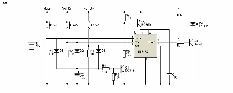
Figure 1 - Remote Control Transmitter
The PCB measures only 78mm x 31mm (3.05" x 1.2"), and accommodates the switches and all components except the two 1.5V AA (or AAA) cells. Any suitable remote control casing will be able to house the PCB, and no special care is needed to install the parts. No surface mount components are used, as these are just too difficult to install by hand. A fair amount of the board is for mounting, and this can easily be reduced to accommodate the PCB in a slim casing (such as the one shown above).
If you don't need the full power from the transmitter, you could increase the value of R9 (47 to 100 Ohms is suggested). As shown with the 10 Ohm resistor, actual peak LED current is around 50mA (in theory it should be much more, but Q3 cannot turn on hard enough). This gives a reasonable range for the transmitter (typically around 5-10 metres, depending on angle of view for the receiver IC), and it should be fine for virtually all applications.
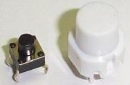 |
The photo shows the two switch styles that will fit the transmitter. Only the small switches are available from ESP, and dimensions are shown in the diagram below. Both are
'tactile' PCB mount types, but the large types are more suited to commercial remote casings because they are tall enough to reach through the casing. If you want to use the larger
switches you can buy them from most suppliers.
The small switches will generally need an additional button on the top, which you will have to make yourself. The diagram below shows the two switches drawn to scale, so the size difference is quite obvious. |
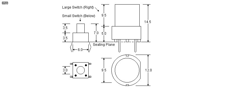
Switch Style Dimensions
Receiver
The receiver is shown in Figure 2, and provides motor drive (forward and reverse) for the motorised pot, and a relay for muting. The relay simply shorts out the preamp's output - this will not cause any damage to the preamp, as long as the relay contacts are connected directly to the output socket. When the circuit is powered on, there is an automatic mute for 10 seconds, but this may be disabled if you don't want it. It is suggested that a LED is used to indicate that the preamp has been muted - this may save you considerable embarrassment sometime in the future. To add the LED, simply wire the LED in series with a 560 Ohm to 2.2k resistor across the relay coil as shown.
Note that LED current can be calculated roughly as (Vs - 2) / ILED, where Vs is the supply voltage and ILED is LED current. Between 5 and 10mA is normally more than sufficient.)
The board is designed to use a relay having a 5V coil, but other relay voltages can be used if desired - note that D1 must be omitted from the board if you use a higher voltage relay. The diode must be connected in parallel with the relay coil, but will have to be mounted off the PCB. Make sure that you size the LED series resistor properly for the voltage you use - 2.2k as shown (with the 5V supply) will not give a bright glow, but this is intentional. You may wish to experiment to get the effect you want.
To use a different relay voltage, simply disconnect the relay return from the 5V point, and connect to a suitable source voltage for the relay (remember to remove D1 from the board and mount it externally, in parallel with the relay coil.
Naturally, if you want to use the mute relay (or mute pulse) for some other purpose you may do so (although I'm unsure what other possibilities there may be that would actually be useful). Note that the mute switching is currently toggled between states with alternate presses of the button on the remote transmitter. Again, if there is sufficient interest in using the mute output for something else, I shall offer an alternately programmed PIC that outputs a single pulse for each button press.
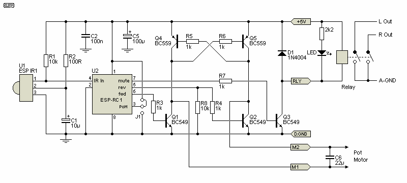
Figure 2 - Remote Control Receiver
Please note that C6 is not mounted on the PCB. This cap must be a bipolar (non-polarised) electrolytic, and it should be mounted directly to the motor terminals with the shortest possible leads to prevent motor noise from causing interference. You may use a smaller cap (100nF ceramic, for example), but to keep noise to the minimum I suggest the value shown.
Q1, Q2, Q4 and Q5 form a full-bridge motor drive circuit. When Q1 conducts, its collector will pull low, providing base current to Q5, which also turns on. This provides positive voltage on the M2 lead and negative on M1. Q2 and Q4 are switched on in the same way. The IC is programmed so that it cannot turn on Q1 and Q2 simultaneously, as this would cause a short across the supply, damaging the transistors.
The complete receiver PCB includes the regulator (shown below), and measures 31mm x 64mm (approx 2.5" x 1.2"). This ensures that it can be made to fit into almost any preamp, although mounting the motorised pot may be a little more challenging if you don't have much space. While we are on the subject of the pot, make sure that you obtain one with a motor that will run at 5V - most will, but there may be some that need a higher voltage. These are unsuitable for this circuit, although it is possible to use a higher voltage pot with a cut track and jumper wire. Details will be available if there is sufficient interest.
The jumper (J1) allows you to select or de-select Power-on Mute (PoM). When the jumper is in the position shown, PoM is enabled and the circuit will automatically mute for 10 seconds at power-up. Place the jumper is the other position to disable the auto-muting (remote mute is not affected, and works with the jumper in either position).

Figure 3 - Remote Control Receiver Power Supply
Finally, the power supply is shown in Figure 3. A very standard 5V regulator, and the applied power may be anything from around 10V up to 25V. At higher voltages a heatsink may be needed. Although the circuit is typically only used for brief periods at any one time, anything is possible in life, and a heatsink is cheap insurance.
Note the separation of the digital ground (DG) and analogue ground (A-GND). These points should not simply be joined - connect the digital ground directly to the centre point of the preamp supply's filter caps, and connect analogue ground to the ground of the output RCA connectors. Failure to follow this recommendation may result in hum or noise on your audio signal.
Construction is obviously impossible without the programmed ICs. These are supplied with the PCBs, as well as the IR LED, IR receiver IC and the switches. All other parts are completely standard. There is nothing especially critical about the construction of the two units. The hardest part will be making a transmitter case (if you want something a bit nicer than the basic cases normally available).
Refer to the photo above - the three switches on the transmitter can be seen down the centre, with the IR LED on the right hand side. There is a choice of miniature tactile pushbutton switches - the small ones are shown, but there is a larger version available as well. These will be supplied with the PCB (only the small switches are available from ESP - details of the different switches are shown above).
The receiver PCB is also shown, and it has everything except the pot and relay on the PCB. Having the pot mounting would have been pointless, since there are several variations of motorised pots, and I could only make a PCB to accommodate one style. This way, any type you wish to use can be connected easily. The dimensions of the receiver PCB are 38 x 76mm (1.5" x 3") - keeping the board small was important, since it has to be able to fit inside a great variety of DIY preamps.
As mentioned above, the receiver board is not designed to hold the pot or the relay. This means that the PCB can be placed in the most convenient location in your preamp, and even allows for a retro-fit. Although the IR receiver IC is designed to fit on the board (in either of two locations), it may be extended a short distance using wires if desired. In some instances, this will make it a lot easier to accommodate in your chassis.
The relay should be mounted as close as possible to the preamp outputs, keeping all signal wiring short. The relay can be held in place with double-sided tape, and the wiring connected directly to the relay pins.
Wiring to the pot is completely conventional. Most motorised pots are log (typically 20k), but if you prefer to use a linear pot wired as shown in Project 01, then you will have to dismantle the log pot supplied with the motor/gearbox, and substitute the innards of a linear pot. This can be done, and although a bit fiddly, it will work well if you are careful.
Remember to route the relay coil wiring well away from input circuits or other high sensitivity parts of your preamp, otherwise you may get clicks and pops through the system when the relay operates.
Transmitter The only way you can really test the transmitter is to use the receiver, unless you have access to an oscilloscope. Safety resistors cannot be used because the IR LED current is too high, so just make sure that you don't make a mistake. The IC will not tolerate reverse polarity or having the supply connected to the wrong pins, so be very careful to ensure it is inserted correctly.
Receiver Connect the receiver to a suitable power supply - remember that the supply earth (ground) must be connected! When powering up for the first time, double check that all wiring is correct - there is no room for errors! If you have made a mistake in the wiring there is a very strong possibility that something will be damaged. When power is applied, the mute relay should remain de-energised for 10 seconds, and should operate after the timeout. Test that the transmitter operates the mute relay (one press of the button to mute, the next to unmute) and the motor drive for the pot. If the pot turns in the wrong direction, simply reverse the wires to the motor.
As always, the artwork for this project is not available, nor is the source code for the microcontroller. Please don't ask, because the answer will be "No". Note that both transmitter and receiver use the same microcontroller - the PCB wiring determines if it will act as a encoder or decoder, based on the initial voltage on pin 5. The kit contents are as follows ...
TransmitterReceiver
- PCB
- Switches (small types only available from ESP)
- IR Diode
- Programmed PIC
- PCB
- IR Detector IC
- Programmed PIC
You will have to obtain the other parts, but they are all completely standard and easy to get. Any ordinary 100mA small signal transistors will work for both PNP and NPN devices (for transmitter and receiver), resistors need only be 5%, and caps are nothing special - anything that fits the board will be quite ok. As always, the full construction details are available in the secure section.
 Main Index
 Projects Index