

|
| Elliott Sound Products | Project 01 |
Some of the following circuits use opamps. No type number has been shown, but industry standard dual opamps are assumed for the pinouts. Feel free to use the opamp of your choice in each case. Depending on your application, you'll use something cheap and cheerful (such as a TL072 for example), or you may want to go 'up-market' and use the LM4562, OPA2134 or something more exotic if it makes you feel better.
Despite the many claims to the contrary, there are no opamps that will improve bass 'authority' (whatever that's supposed to mean), nor will they be bass shy, cause 'veiled' top end or any of the other rather remarkable claims you will see on the Net. Differences are certainly measurable, but all standard opamps have response that's flat to DC. Some don't care for high loading (low impedances) and will show relatively high distortion, and others may be noisy.
Typical opamps that are commonly used for audio include ...
The above isn't comprehensive, and is but a small group. There are hundreds of different types, some outrageously expensive, others very cheap. Extra cost doesn't necessarily get you an opamp that will sound 'better' than another, so use whatever you are most comfortable with.
The volume control in a hi-fi amp or preamp (or any other audio device, for that matter), is a truly simple concept, right? Wrong. In order to get a smooth increase in level, the potentiometer (pot) must be logarithmic to match the non-linear characteristics of our hearing. A linear pot used for volume is quite unsatisfactory.
Unless you pay serious money, the standard 'log' pot you buy from electronics shops is not log at all, but is usually comprised of two linear sections, each with a different resistance gradient. The theory is that between the two they will make a curve which is 'close enough' to log (or audio) taper. As many will have found out, this is rarely the case, and a pronounced 'discontinuity' is often apparent as the control is rotated.
As with all pots used as volume controls, the first 10% of rotation causes a very large variation in level (essentially from 'off' to quietly audible). A 'true' log response over the full range of perhaps 100dB is not really useful, because most of the time the gain is varied over a relatively small range. 25dB of variation is a power ratio of 316:1 - this will normally be the range over which any volume control is used.

Figure 1 - Circuit of the Log Pot Approximation
Take a 100k linear pot (VOL), and connect a loading resistor (R = 10k - 15k, 12k used to produce Figure 2) as shown above to achieve the curve shown. It should be a straight line, but is actually still far more logarithmic than a standard log pot. For stereo, use a dual-gang pot and treat both sections the same way. Use of a 1% resistor for R is recommended. Different values can be used for the pot, but keep the ratio between 6:1 to 10:1 between the value of VOL and R respectively. While 8.33:1 (as shown) is close to a real log curve, it may still allow excessive sensitivity at low levels. Higher ratios than 10:1 can be used, but will cause excessive loading of the driving stage, or necessitate the use of a pot whose resistance is too high.
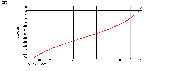
Figure 2 - The Transfer Curve in dB
Provided the gain structure of the preamp is set up properly, a good approximation to true log pot operation is obtained over at least a 25dB range, which is sufficient for the normal variations one requires.
The gain structure of the preamp is correct when the pot spends the vast majority of its time between the 10 and 2 o'clock positions. If the volume is often below or above this range, consider changing the preamp gain. The gain can be switched to give a 'two-stage' volume control, so that the optimum setting is always available.
The other advantage of the 'fake' log pot is that linear pots usually have better tracking (and power handling) than commercially available 'log' pots, so there will be less variation in the signal between left and right channels. The tracking may be improved even further by the added resistor, which will allow a cheap carbon pot to equal a good quality conductive plastic component (at least for accuracy - I shall not enter the sound quality debate here).
Make sure that the source impedance is low (from a buffer stage) and that it can drive the final impedance when the control is fully advanced (it may be as low as 10.7k Ohms with a 100k pot and a 12k loading resistor). Use of a high impedance drive will ruin the law of the pot, which may no longer resemble anything useful.
Originally designed by Peter Baxandall (of feedback tone control fame, amongst many other designs), there is also an active version of the 'Better Volume Control', which uses an opamp and a pot in the feedback loop. The log law is almost identical to that for the passive design above, but it can provide gain as well as attenuation. An example of this design may be found in Project 24, and the circuit for the basic idea is shown in Figure 3.
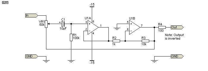
Figure 3 - Active Logarithmic Volume Control
The buffer (U1A) enables the inverting stage (needed so the circuit can work) to have a very high input impedance. This would otherwise not be possible without the use of extremely high value resistors, which may increase the noise to an unacceptable level. The maximum gain as shown is 10 (20dB) and minimum gain is 0 (maximum attenuation). The input impedance is variable, and is dependent on the pot setting. At minimum gain, input impedance is the full 50k of the pot, falling to about 27k at 50% travel, and around 4.3k at maximum gain. The impedance is much less than that of the pot itself because of the feedback from the final opamp.
These impedance figures are similar to (but a little lower than) the simple passive version (if a 100k pot is used), and again, a low impedance drive is required or the logarithmic law will not apply properly. The actual value for VR1 does not matter, and anything from 10k to 100k will work just as well, although it will influence the input impedance. The error at 50% of pot travel is less than 5% with values from 10k to 100k.
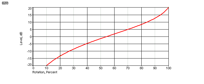
Figure 4 - Response Vs. Rotation Of Figure 3
Note that the additional benefit of improved tracking may not apply to the active version (at least not to the same extent), so use the best pot you can afford to ensure accurate channel balance. With 20dB of gain at maximum, this will be far too much for many preamps. 10dB of gain is normally sufficient. Increase R2 to get less gain (3.3k will reduce the gain to 10dB, close enough). Doing so will also increase the worst-case input impedance.
The following trick has been used in a few guitar amps, but because it uses a dual-gang pot isn't suitable for stereo because 4-gang linear pots (well, any 4-gang pots) are next to impossible to obtain. The approximation to log is very good over at least a 30dB range, but it's only marginally better than the version shown in Figure 1, but requires a dual-gang pot to get there.

Figure 5 - Log Approximation Using Dual-Gang Pot
The response vs. rotation is shown below. Across the final 25dB range it is almost a straight line (i.e. truly logarithmic). This is a good way to get a smooth response from the pot, but as already noted it's only really usable for a mono system. This rather limits its usefulness.
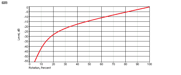
Figure 6 - Response Vs. Rotation Of Figure 5
However, there is an important difference between the above and most other versions. If a gain stage is used between the two sections of the pot, there can be a useful reduction of noise if everything is set up properly. The gain stage can provide a comparatively large amount of gain (up to 20dB isn't unreasonable), and unlike having that much gain in front of a 'normal' or 'law faked' log pot, if there's a high level signal, the preamp won't clip - unless you want it to do so of course.
This is a handy usage of the dual pot version, and in some respects it's similar to an active control (Figures 2 and 9), but (typically) without the signal polarity inversion. This makes it more useful than it may appear at first look. If a stage with 20dB gain (x10) is fed from a 2V RMS source, it will clip heavily (assuming ±15V supplies and a typical opamp). With the circuit shown, the level control may be set at (say) 30%, output level is 1.9V RMS, and there is no clipping. The noise (and signal) from the gain stage is attenuated by 10.5dB, and the effective signal to noise ratio is improved by the same amount. If the gain stage simply followed the pot, its noise is present all the time, at all pot settings.
For anyone needing a multi-channel true logarithmic volume control, see Project 141. The project uses THAT2180 VCAs, and can be set up as anything from 1 to 8 channels (or more if you have a use for more than 8 channels). It's ideal for home theatre systems, and you only need to include channel switching for a complete preamp. The VCA also provides gain, so is essentially a complete preamp as described.
Bernd, a reader of The Audio Pages, has contributed a useful variation - in this case, a 'better balance' control. Note that the configuration described requires a high impedance load, and the passive 'Better Volume Control' cannot be used in this circuit. Used in the manner shown, it is a very similar concept to the better volume control of Figure 1, except it is (in a sense) the same idea in reverse.
Bear in mind that many (especially early Japanese) designs use a specially designed pot for balance, and these are not suitable for the circuits shown below. These pots commonly have a centre detent, and the resistance of each track remains very low from the centre position to one end (or the other) of travel. These 'special' pots are characterised by the level remaining constant in one channel or the other as the balance pot is moved. The overall law of these controls is (IMO) unsatisfactory for hi-fi.
A standard configuration of Balance/Volume control using conventional pots (1 channel) is shown below:

Figure 7 - Conventional Balance / Volume Control
BAL = 2.5 × VOL
For example: VOL = 10k log, BAL = 25k linear
Adding a resistor 'R' gives opportunity for two interesting improvements of the standard balance-volume-control networks. Note that the switch is optional, and may safely be left out (i.e. shorted).

Figure 8 - Improvement With Added Resistor
A) R = VOL (for example, 10k)
The BAL-pot is 'virtually absent' when in the centre position:
In the centre position the resistive track of BAL only affects the load for the previous stage, since there is no current through the sliding contact (so you could open switch 'Sw1' without changing anything at all - if you please). This seems to be reasonable: As long as you don't manipulate the balance control it is virtually absent from the circuit (no signal passes through its sliding contact). Hence quality (or age) of the BAL-pot doesn't matter at all then.
Sonic detriments can only come into play for two reasons:
Thanks to 'R', the balance control operates conveniently slowly near the centre position and overall volume is affected significantly less than without it. This leads to another option:
B) R = 4k7 (R = ~0.47 × VOL)
The balance knob works without affecting the overall volume
This will give best operating convenience since the sound stage then moves from the left to the right without significant overall volume change. Input voltage on both channels constant and equal, the sum of Left and Right channel power remains approximately (±0.2dB) constant across about 80% of the dial (which still works conveniently slowly about the centre position). I decided on the .47-factor after some PC-simulation and checked it by implementation in my preamp afterwards:
It works as expected indeed (there is just a slight increase of overall volume at the extreme right and left positions). I don't want to miss out on having a balance control any more, since there are in fact records which suffer from severe channel imbalance. Moving the armchair or the speakers is not a convenient cure for that. Moving the soloist two feet to the left or right without changing the overall volume, just by activating the balance knob, is the way to go.
Any compromise between 'golden-ear -' and 'maximum-convenience -' versions is possible by selecting a suitable 'R/Vol factor' between 1.0 and 0.47  .
.
The impedance of these 'enhanced' networks is approximately that of 'VOL' alone (if R = Vol and BAL ~ 2 × VOL), so you can add BAL and R to any 'purist' design without changing critical parameters of the circuit (4-6dB attenuation by R will occur, of course, so you will have to add about 5 or 10 degrees of arc on the volume dial in future). Even when BAL is set to the extremes there is only a moderate change of load (max.: -30%) which will not upset any reasonable preamp.
If there already is a standard network in your amp, it is easy to add the additional resistors ... Just solder them across the corresponding pins of the balance pot (on one channel from centre to the left and on the other from centre to the right!) The volume pot is not involved.
Bernd Ludwig
Another contributed idea, this one is also simple and works very well. It's disadvantage is the the input impedance is variable, and falls to 1k (the value of R1) when set for maximum volume. Input impedance with the pot centred is 5k, and it's just over 7.8k with the pot at minimum (infinite attenuation). Provided the circuit is driven by a low impedance (such as another opamp that can handle a 1k load), the variable impedance will not be an issue. C1 is optional, and provided the source has a low DC offset it can be left out (shorted).
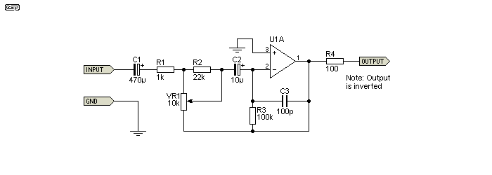
Figure 9 - Alternate Active Volume Control
R1 can be increased to reduce the maximum gain. As shown it's 19dB, and if R1 is increased to 3.3k it falls to a more usable 8.8dB. The log response is not affected.
The effective law of the pot is shown below, and it's remarkably similar to the others shown. However, the response close to maximum is a little closer to being 'real' log.
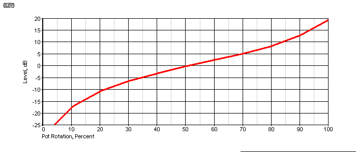
Figure 10 - Response Vs. Rotation Of Figure 9
Idea contributed by Michael Fearnley
Reverse log pots aren't needed very often, and this is probably a good thing because they are close to unobtainable. Probably the easiest way to get one is to buy a dual-gang 'log' pot, of the style where the wafers are opposites (mirror images of each other). 16mm style pots are usually of this construction (see below). Success depends on your abilities with mechanical contrivances, and what tools you have at your disposal.
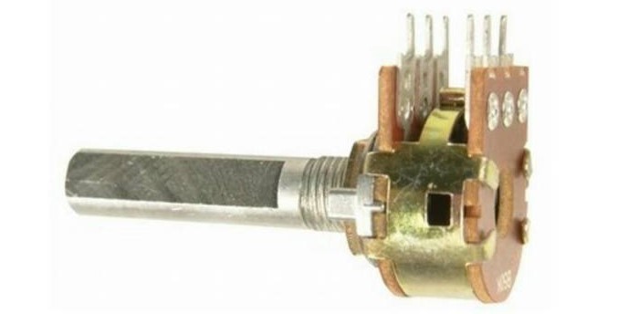
Figure 11 - 16mm Dual-Gang Pot Example
You need to dismantle the pot so the front and rear wafers can be swapped. When you re-assemble the pot, the front wafer is used at the back and vice versa. You now have a dual-ganged reverse-log pot. It will only ever be as good as an 'anti-log' pot as it was 'log' (i.e. not wonderful), but it is now at least nominally a reverse log pot. Whether you use one or both sections is immaterial (if you need a mono pot, you could parallel the two sections).
I leave the details of how to dismantle and re-assemble the pot to the reader. It's probably a good idea to get a couple, in case you mess up one in the process. This is not an ideal arrangement, but it should work fine if you can get it back together and working smoothly. This may be harder than it sounds, depending on the internal construction. Note that this will only work with a pot like that shown - if the two wafers are not mirror images, swapping them will achieve nothing - the pot will still be 'log'.
 Main Index
 Projects Index