
|
| Elliott Sound Products | Project 103 |
I must first explain at the very outset that this standard phase controller is usually not very helpful, and can do more harm than good in many cases. The reason that I'm publishing a circuit for a continuously variable phase controller is simply that I have had many enquiries for one.
Having said that, these controller circuits are very common in subwoofers, and if used properly can help to integrate a sub with the main system. Being able to vary the phase can allow a sub to blend seamlessly with the main speakers, but it must be understood that the phase will only ever be right at one frequency. This can cause peaks and dips in the response to simply change their frequencies, without much overall benefit.
Before embarking on this project, please see The Subwoofer Conundrum and Phase Control - Myth or Magic. These articles shed much light on the subject.
The circuit is completely conventional, and has been around almost forever in one guise or another. Similar circuits were used in the valve (tube) era, so there is nothing new about it. Parts of the circuit have already been published on these pages as a guitar tremolo circuit, but fairly obviously, that is not suitable for this purpose.
The circuit uses a dual opamp, and it must be supplied from a low source impedance because the first stage is a switchable inverter. If driven from the output of a crossover (opamp based), the impedance will be fine. Most preamps can drive the circuit directly with no changes needed.
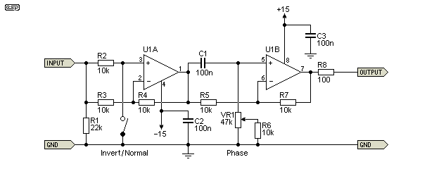
The first stage is a switchable inverter. With the switch open, the signal's phase is unaffected and it passes straight through with unity gain. Closing the switch causes the circuit to invert. This method was used because it only requires a single pole switch, making it easier to wire and probably cheaper as well. The phase shift network sums the two signals applied to the opamp's inputs, and the amplitude remains unaffected - it is flat at all settings of the pot. Another name for this circuit is an 'all-pass' filter, because it passes all frequencies equally, affecting only the phase.
The circuit can shift the phase from 180° (out of phase) through to 0°, but the useful range is between about 160° and 20°. The 90° frequency is determined by the formula ...
F90 = 1 / ( 2π × R × C )
where R and C are the resistor + pot (VR1 + R6) and the input capacitor (C1) to the opamp. See below for the phase plot using 20% increments of the pot.

Figure 1 - Phase Controller Schematic
There is nothing special about the circuit, and a TL072 opamp will be more than adequate for any subwoofer system. VR1 is the phase control pot, and should be linear. No special precautions or close tolerance resistors or caps are needed. The phase switch (open = normal, closed = inverting) needs some explanation, since the phase can already be varied from 0° through to 180°, so the switch is redundant, right?
Not so as it turns out. Because of the way the phase control works, interactions from crossovers and subwoofer placement may require that there is a full phase inversion as well as phase shift. See Phase Control - Myth or Magic for more.
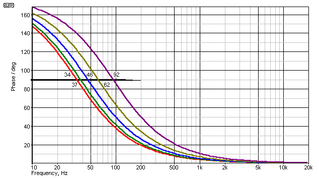
The response of the phase circuit is shown below. The graphs are shown for pot rotations of 0 to 100%, at 20% intervals. The lowest frequency is obtained with the maximum pot resistance and vice versa. The 90° phase shift frequencies are shown in ascending order, from a low of 34Hz to a high of 92Hz. The range is easily changed if necessary by changing the value of C1 - higher values will give lower frequencies, and lower values will give higher frequencies. Any 90° frequency is easily calculated using the formula above.

Figure 2 - Phase Response of Controller
Note that although the centre frequency is defined as the 90° phase shift frequency, the phase is affected over a wide range. There will be noticeable phase disturbances over ±2 octaves for a total span of 4 octaves, with actual disturbance extending for ±1 decade. This is the reason I don't like the circuit, as it creates a situation where the actual phase is something of an unknown - you could be making things better at one frequency, while making it worse at another. This is unlikely to cause major problems with a subwoofer, but great care is needed to get it set up with the optimum phase angle.
The circuit is easily made on a piece of Veroboard or similar. All resistors can be 5% carbon, although metal film may give slightly less noise. Caps are standard polyester (or ceramic for the opamp bypass caps) and should be rated at 50V.
 |
The standard pinouts for a dual opamp are shown on the left. If the opamps are installed backwards, they will almost certainly fail, so be careful. A TL072 opamp will be quite satisfactory for most work, but if you prefer to use ultra low noise or wide bandwidth devices, that choice is yours. Suitable choices include the OPA2134, NE5532, LM4562, etc. The NE5532 is probably the best value for money opamp you can buy. |
There are no special precautions that you need to take with construction. Use of a clean power supply is highly recommended, having a typical voltage of ±15V (e.g. Project 05 or similar).
Connect to a suitable power supply - remember that the supply earth (ground) must be connected! When powering up for the first time, use 100 ohm to 560 ohm 'safety' resistors in series with each supply to limit the current if you have made a mistake in the wiring.
The circuit is working properly when the voltage dropped across the safety resistors is no more than a few volts - the exact voltage depends on the opamps and value of safety resistor. The output pins of the opamps should show close to zero volts, and nothing should get hot.
Check the circuit with an input from a music source or oscillator - the output signal should be clean and undistorted. Remember that you will need a power amplifier after the phase controller - it cannot power a loudspeaker.
 Main Index
 Projects Index