

|
| Elliott Sound Products | Phase Correction - Myth or Magic |
Copyright © 2004 - Rod Elliott (ESP)
Page Updated 25 Jan 2024
 Main Index
 Articles Index
Phase Correction - Myth or Magic? Does it actually work? Although recommended in a lot of designs (especially for subwoofers), you cannot really correct a time delay with a phase shift network, but you can improve performance, albeit marginally some would say. An all-pass filter (aka phase shift network) may be useful in some cases, but it is certainly not the panacea that some would claim.
The best one can hope for (and it does depend a lot on the time delay you are trying to correct) is to convert a deep dip in response into a much shallower ripple at or near the crossover frequency, but it is entirely possible that the end result will not sound as good as if the dip were just left alone.
This topic has received scant attention at most of the speaker building sites, forum pages and published books on the subject, but is obviously important since it has the potential to make matters worse than they were before you started. A discussion about 'time alignment™' has already been done on The Audio Pages - see Phase, Time and Distortion in Loudspeakers for the full discussion.
Unfortunately, it is difficult to achieve true time delay in the analogue domain - it can be done, but requires a large number of components to be placed in the signal path. Since the tweeter is the driver most likely in need of the delay, this means potential degradation of the higher frequencies, something that is commonly quite audible.
However (and the above notwithstanding), achieving 'time alignment' by whatever means you have available can be well worth the effort. You must be able to take accurate measurements before you start so the effects of any change can be plotted. The ideal is a true time delay, and that means using a DSP. There are no commonly available time delay ICs that have the necessary fidelity for hi-fi usage, and those such as the Project 26A are even further limited because very short delays are not possible. Most systems will need a delay of no more than 100µs, and often less.
A time delay is introduced whenever the acoustic centres of any two loudspeakers are different from the perspective of the listener. It is not usually a problem in a three way system between the woofer (or subwoofer) and midrange or mid-bass, but between the mid/ mid-bass and tweeter there is usually considerable room for misalignment in the time domain.
For this exercise, I have used a crossover frequency of 3.0kHz, and the offset between drivers' acoustic centres is 100µs (or 35mm, close enough). It is useful to establish the relationship between distance and time, and this may be determined by ...
λ = c / f Where λ is wavelength, c is velocity & f is frequency t = 1 / f Where t = time (period)
So for any given frequency we can determine the wavelength and period (the time for one complete cycle). For example, at the selected crossover frequency of 3.0kHz, the wavelength is ...
λ = 343 / 3000 = 114mm t = 1 / 3000 = 333µs
It is useful to understand that there is a simple relationship between time delay and effective 'phase' shift in terms of wavelengths and the velocity of sound in air (343m/s at sea level, approx 20°C and 50% relative humidity).
For example, if the delay were 166µs, a 3.0kHz signal is delayed by exactly 1/2 wavelength, or an equivalent distance of 57mm. This can also be determined by realising that sound travels 0.343mm/µs, making calculations rather easier.
While it is possible to make a phase shift network that has a consistent phase shift over a wide range of frequencies, this is not the same as time delay. It can be considered obvious that if two signals are delayed in time by exactly the same amount that the end result is identical to no time delay at all. Likewise, if two signals are affected by identical phase shift networks, the net result is again the same (although there is now a phase shift in the signal which may or may not be audible, depending on many different circumstances).
Having a time delay (in the case of loudspeakers introduced by a physical misalignment of acoustic centres), and attempting to correct this with a phase shift simply may not work as well as one might hope. This should be obvious, but it is still a useful way to realign the drivers. This can be shown in the simplest case with a time delay that is exactly 1/2 wavelength. For a 3kHz crossover point, this equates to wavelength ÷ 2, or 57.5mm (which can also be described as a time delay of 166µs). The graphs shown below are all done using a 24dB/octave Linkwitz-Riley crossover - the effects with lower orders are very much worse than shown here.
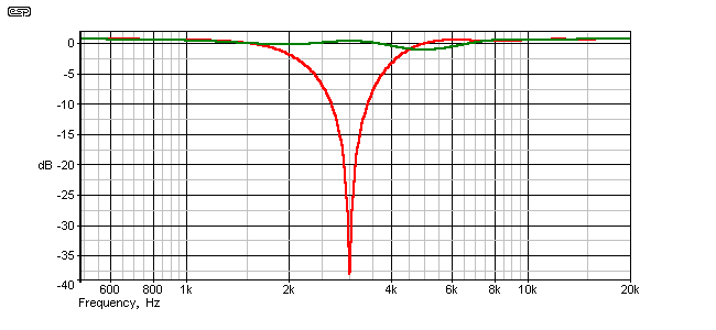
Figure 2.1 - Frequency Response With 57mm Acoustic Centre Offset
The red graph shows the response without phase reversal of the driver, and it is very obvious that there is a significant response dip at the crossover frequency. This was done using electrical summing, which is much more severe than acoustic summing, however the 'suck-out' would be very audible indeed.
The green graph is the response with the tweeter reversed in phase, and it looks better than it really is because of the graph scale. However, the response ripple is still within (barely) acceptable limits, at -1.7dB at 4.9kHz. Again, this is with electrical summing - the acoustic response will be somewhat better than shown.
Next, we see the response of the same system, but with a 100µs delay. With the tweeter wired out of phase, the response dip is 2.8dB, and when wired in phase it is 5.8dB - the anti-phase connection is better, but neither is acceptable.
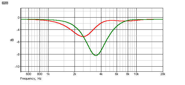
Figure 2.2 - Frequency Response With 35mm Acoustic Centre Offset
As you can see, both graphs show a distinct dip in response (the red graph is the out of phase connection). Acoustic summing will give a result that is slightly better than what you see here, but it will still be audible. The optimum fix is a digital delay that will hold the tweeter signal back by 100µs, but this is an expensive option. The next diagram (Figure 2.3) shows the response using a single all-pass filter (phase shift network) that has been optimised to get the best response possible from the combination of drivers and time delay.
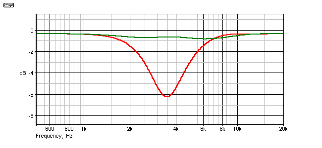
Figure 2.3 - Frequency Response With Phase Compensation
The maximum deviation of the phase corrected version (shown in green) is now 0.51dB, at 6kHz. It is actually possible to improve on this slightly, but in practice this requires accurate measuring equipment. Attempting to perform an adjustment of this nature without measurements will simply lead to confusion and great bafflement, since you have no flat reference for comparison. The setting that sounds the best (to you) may be the result of personal preference or acclimatisation to the sound, and it is very possible that it will not be correct.
In addition to the phase adjustment, it is important that polarity inversion is available. Although the above example uses normal polarity for best results, this will not always be the case. If the polarity is incorrect, no amount of phase adjustment will ever make the situation better, but it can easily make it a lot worse. For example, the response shown in Figure 2.3 is totally changed (and very much for the worse) if the phase is inverted.
The standard and traditional all pass filter (phase shift network) is shown in Figure 2.4 - note that there are two variants, and their behaviour is completely different when phase aligning a loudspeaker. 2.4.a shows a non-inverting configuration, and 2.4.b is inverting. This is something of a misnomer, since both circuits will have an output whose phase is frequency dependent, but version 2.4.a leaves low frequencies alone and inverts high frequencies, while 2.4.b inverts low frequencies. At the mid frequency of the network, the phase is rotated by 90°, but note that this is not necessarily aligned with the crossover frequency.
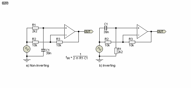
Figure 2.4 - Inverting and Non-Inverting Phase Shift Networks
The networks themselves are virtually identical, with only the position of the resistor and capacitor (R1 and C1) changed. This effectively reverses the frequency at which there is no phase shift - in this case we would arbitrarily select around 10Hz as the 'reference' frequency. At such a low frequency, the capacitor has virtually no effect with either network, and the circuits can be considered to be (almost) conventional inverting and non-inverting opamp circuits.
The time delay of these simple phase-shift networks can be approximated by ..
Delay = R1 × C1 × 2 So ...
Delay = 2.2k × 39nF × 2 = 172μs
There are many other formulae that you can throw at phase shift (delay) networks, but most aren't especially useful. While the formula shown is an approximation, it works well for the most part. In many cases you may need to use several networks in series, as this can provide flatter group delay over a wider frequency range. I leave such experiments to the reader.
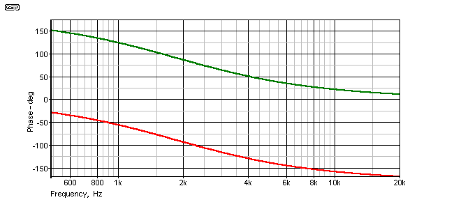
Figure 2.5 - Inverting and Non-Inverting Phase Shift Response
The networks as shown are exactly the same as those used for the alignments shown above. The centre frequency for optimum alignment is not 3kHz as one might expect, but for the example shown is 1,856Hz. Phase shift at 3kHz is 116° or 64°, depending on the phase polarity selected. 116° is the phase shift that gave the best result.
If everything has worked as intended, we should get a good correlation between the applied phase shift, time delay and wavelength. Since we know that the time delay used was 100µs and frequency was 3.0kHz, we can calculate the effective wavelength that corresponds to the phase shift ...
| Wavelength | 115mm |
| Time Delay | 100µs |
| Distance Offset | 35mm |
| Phase Shift | 116° |
| Effective distance compensation | (115mm / 360°) × 116° = 37mm |
Well, that seems to be very close indeed. Since the non-inverting phase shift network was used, it has 116° of shift at 3kHz (after careful adjustment), hence the calculation above for the 'effective distance compensation'. Now, looking at the graphs, it is obvious that they are not perfect, but the end result is a lot better than one could expect without any compensation at all.
Sidenote
There is a relatively simple way to introduce a time delay at any frequency. Coaxial cable has a velocity factor of around 0.7 (typical) - that means that the signal travels at 0.7 of the velocity in a vacuum. Unfortunately, 100µs is rather a long time, so given that normal speed of a signal is 3 × 10⁸m/s, for a velocity factor of 0.7 (for example), we would need 3 × 108 × 0.7 = 210km (kilometres!) for a one second delay.
Therefore, 210 metres will give a delay of 1µs, so you would need 21km of coax to obtain the required delay of 100µs. For what that would cost, one could purchase any number of digital delays. In case you were wondering, the idea is not completely silly. High-end oscilloscope manufacturers used to include a coax delay line to delay the signal for the few nano-seconds that it would take for the trigger circuits to operate, so that one could examine the leading (or trailing) edge of pulse waveforms without a 'glitch' at the beginning of the trace. This typically only required a few metres of cable (perhaps 10 metres at the most).
Lest one think that knowledge of such technology is restricted to old buggers like me, a web search will reveal that there are still a great many manufacturers of coax delay lines, and they are far from dead. They just happen to be useless for this application.
The sidenote above also shows how silly it is to imagine that speaker leads have to be the same length to prevent the sound stage shifting to one side or the other. Feel free to make speaker leads the length they need to be, and don't be distracted by nonsense that you'll see from the 'mad cable brigade'. Nothing to do with the topic, but worth remembering anyway.
So, it's fair to say that phase correction/ 'time alignment' is neither myth nor magic, but is simply down to basic physics. It's vitally important that 'before' and 'after' results are measured using the exact same setup for each set of measurements. It's also important to ensure that your measurements aren't affected by measurement artifacts - reflections from nearby surfaces, mic anomalies, extraneous noise, etc.
While this discussion has dealt only with 24dB/octave Linkwitz-Riley alignment crossovers, the principles are recommended by many to be applied with other orders as well. First order (6dB/octave) crossovers are likely to benefit the least, because the time delay created by a phase shift is too narrow, and is completely incapable of creating an offset that is broad enough to be useful. This is illustrated below, where the same time delay (100µs) was used, and modification of the phase shift network was only able to achieve the response shown.
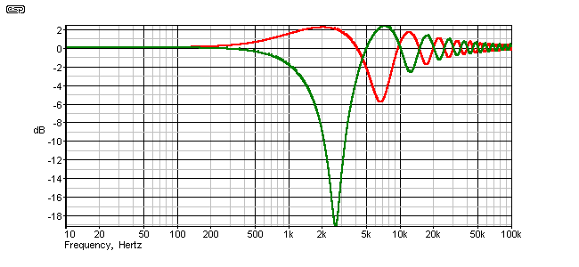
Figure 3.1 - Applying Phase Correction to a 1st Order Crossover
Note that the uncorrected response is a lot worse than the corrected response, but even there, the ripple is over 7dB in peak variation. The best one could say for the response is that it is appalling, both before and after 'correction'. There are terms that describe it far more accurately, but they will not be used here. 
It is fairly obvious that since the range over which an all pass filter can be used is quite narrow, it becomes more effective as higher order filters are used. While it has been shown that the effects are reasonably good with 24dB/octave crossovers and useless with 6dB/octave, it follows that 12dB and 18dB crossovers will fall in the middle, with 12dB types being considerably worse than 18dB networks.
It is worth noting that a phase reversal of the all pass filter changes very little. The first major peak is converted into a dip, but the overall ripple remains the same, at 7dB. As always, these tests were done with summed electrical signals, so the acoustic effects will not be as severe ... but! They will still be there, and will be audible.
The next chart shows the response of a corrected and uncorrected 12dB/octave filter. This filter is the same frequency as before (3kHz), has the same 100µs delay, and is a Linkwitz-Riley aligned type. A phase inversion is mandatory for 2nd order filters and there is no point showing the result without it. (Hint - a 10dB dip at 3kHz is not a pretty sight.)
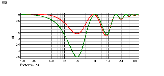
Figure 3.2 - Applying Phase Correction to a 2nd Order Crossover
The result is not completely dreadful, but it is certainly 'sub-optimal' (a kinder and gentler way of saying what I really think  ). Again, electrical summing is the worst case and the acoustic response will not be quite as bad. A phase shift network will probably rescue an otherwise unusable design in this case.
So, is an all pass filter a panacea for misalignment problems? Quite obviously not, since even at 24dB/octave the ripple is quite visible, and will be quite audible as well to anyone who knows what to listen for. However, it is still a lot better (at least in the amplitude domain) than nothing at all. Stepped baffles used to time align the drivers may look quite high-tech, but the step creates what I refer to as a 'diffraction engine' - a set of internal and external angles that will create interference patterns and response anomalies that are difficult to predict, but will certainly not improve matters.
What of sloping baffles? While there are no untoward diffraction effects (other than those found in any relatively conventional enclosure design), one is forced to listen to both drivers off-axis at all times. While the deviations may be small compared to on-axis response, they are nonetheless audible, especially where the mid-bass is working at the limits of its frequency range. For those who claim that all baffles with more than one driver should (must) be sloping to get time alignment, consider the difference in path length from the top and bottom of the mid-bass to the listener, and then compare that to wavelengths. Exactly the same effects are at work as with separate drivers, and this is the main reason that off-axis response of large diameter drivers is so poor.
One parameter that is potentially very important is group delay. The uncorrected 6dB filter shows a group delay that peaks at 0.8ms (800µs), so in one respect we can be thankful for the fact that there will be a deep notch at that frequency, so the (very) delayed signal will not be audible. The concept of group delay is best explained by a fairly common description on the Net. If the treble were to be reproduced 5 minutes (or even 5 seconds) after the bass and mid, this would be noticed by even the most non-critical listener.
Fortunately, this is not common even with the cheapest of speaker systems, but it illustrates the point. In reality, group delay (the delay introduced to any frequency relative to any other frequency), is normally very low, but can still be audible, and the audibility is frequency dependent. In the case of the mid-bass to tweeter crossover, a delay of 100µs would be fairly typical, and is less than 1 cycle of the signal at typical crossover frequencies (a 'periodic time' of 100µs represents a frequency of 10kHz). Although this delay in and of itself is inaudible, the phase cancellation effects are very audible indeed.
This is not going to be covered further here, not only because it will confuse the issue and make the processes described seem more complex, but also because I do not have enough data on the audibility of group delay to make an informed comment.
For those who might wish to get a little background into group delay, see the discussion at TrueAudio.
The material above is in the interests of promoting an understanding of the concepts, rather than a full description of how one should go about applying a phase shift network to a system. In general (and as explained by Siegfried Linkwitz), phase shift networks should ideally have a 90° frequency that is above the crossover frequency. Because they then have less delay, you will need to use two or even three networks to obtain the phase correction needed.
By making the frequency higher than the crossover, it is possible to obtain a much better result, with ripple reduced to 0.1dB or so, however, because this requires two phase shift networks instead of one, some constructors may not like the idea of adding even more active circuitry to the high frequency end of the system.
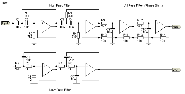
Figure 4.1 - Practical 24dB Crossover, With Phase Correction for 100µs Driver Offset
The drawing shows a 3kHz 24dB crossover, with a two-stage phase correction circuit. This network is designed for a 100µs driver offset, and the summed response is within 0.2dB of being perfectly flat. Because the 90° phase shift frequency is above the crossover frequency, two stages are needed to get sufficient delay. Using a delay circuit with a frequency that is lower than the crossover allows a single stage to be used, but the results are not as good.
Naturally, if your offset is different because of the drivers used, the phase shift network will need to be modified to suit. Ultimately, the response (phase and frequency) of typical drivers is usually not ideal, so it is unreasonable to expect that anything you do will make the system perfect. All one can ever hope for is to get it as good as possible, and choose drivers very carefully to get the smoothest response you can.
A fact of life though ... the smoothest drivers in the world do not guarantee that the sound will be 'good'. There are many other influences that can be far more important than a perfectly flat frequency response, so never expect that application of phase shift network(s) will make your system sound better. Sometimes, a more musical result is achieved without having to do anything. It may not be absolutely accurate, but if it sounds good with a wide range of music then you may never need to go any further.
The same techniques can be applied with lower order crossover networks too, but low order networks become far more difficult to align. Because the two drivers operate over a wider frequency range in the crossover region, the delay needs to be flatter over a much wider range too - this becomes very hard (and uses a lot more components). The network shown above is completely unsuitable for a 12dB network for example, resulting in a dip of 2dB at 11kHz. Mind you, without the network, there is a 17dB dip at 4.7kHz, and I know which would sound more objectionable.
For those who may want to calculate the delay, the formula is ...
Delay at fxo = tg tg = 2 × R × C / [ 1 + ( fxo / fo ) ² ]
(where fxo = crossover frequency, tg = group delay, and fo = 1 / 2π × R × C (in phase shift network))
In the above example, you will find that the group delay is not 100µs as might be expected. At the crossover frequency, the delay is about 86µs, but when combined with the crossover, this was found to give the best summed performance. If you do choose to use a phase shift network to correct for a specific time delay, you will probably have to make it variable by using pots in place of R9 and R12. A straight calculation is unlikely to give you the response you want, so measurement (or simulation) is essential if you want the best possible result.
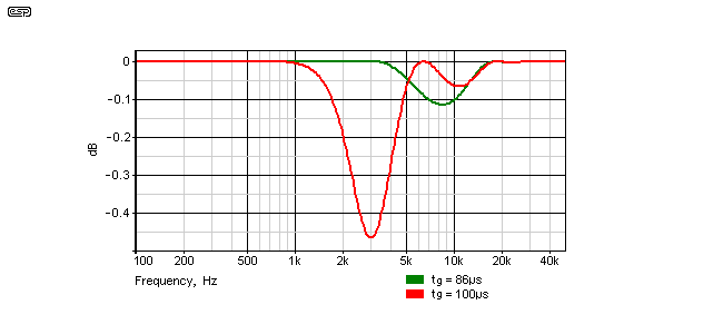
Figure 4.2 - Effect of Using 86µs Delay (Green) vs. 100µs (Red)
It is apparent from the response graph above that performance is much better with the shorter delay, even though it may be theoretically incorrect. The error isn't great - at less than 0.5dB it's far smaller than you'd expect from driver anomalies - but the shorter delay is still preferable. There is bound to be a mathematical explanation for the variation from the expected group delay, but I won't be looking for it. 
 Main Index
 Articles Index