

|
| Elliott Sound Products | Induction Lighting |
 Main Index
 Lamps & Energy Index
Induction lighting was almost unheard of only a few years ago, but is now a serious contender for many large area lighting applications. Warehouses, street lighting and general open-area lighting are perfect matches for induction lamps.
There are many claims made for induction lighting, including the rather frivolous 'factoid' that it was pioneered by Nicola Tesla. While it is true that Tesla made lamps light wirelessly from afar, there is little correlation with the process as used today. I suppose it makes a nice-sounding story though, and why should we let facts get in the way of a ripping yarn. 
Other (equally frivolous IMO) claims are made for the operating frequency used, with some claims that it ranges from 2.65 to 13.6MHz. It's interesting that information that is so wrong is so precise - the two induction lamps I've measured operated at 137kHz and 250kHz. This is far more in line with what can be realistically achieved easily with available components, and is the actual measured frequency rather than what appears to be disinformation.
Another (false) claim is that there is little or no heat generated. Not so! After 15 minutes of operation, one of the lamps I tested was way too hot to touch (the other was enclosed, but it was very obvious that it, too, got rather hot). I measured the temperature at 116°C - hardly what anyone would call 'cool'. Regardless of the mode of operation, anything that is not 100% efficient (in this case, turning electrical energy to visible light) will have to dispose of the unused energy - the most common form of waste energy is heat.
You will often see induction lamps referred to as 'LVD' lamps. As near as I can tell, LVD is a trade mark, but has become somewhat generic when it comes to these lamps. I've not been able to determine if LVD is an acronym for something meaningful - a search revealed nothing of any apparent relevance.
There is no single lighting technology that is perfect in all respects. Sunlight is the standard against which all lighting must compete, and no artificial light source can equal the spectral distribution of sunlight. Some sources come very close, and the humble incandescent lamp (in one guise or another) will still be used where an extremely high colour rendering index (CRI) is needed. Being almost perfect in this respect, incandescent lighting will probably never go away for some applications. Beware the claims that the CRI of incandescent lamps is no better than 80 (or sometimes much lower) - this is simply wrong (more disinformation).
Induction lamps are really just fluorescent lights - with several important changes. Unlike a traditional fluoro, they have no electrodes, and this removes the primary problem area. Electrodes degenerate with age and use, and are especially affected by starting the tube. This is why all fluorescent lamps (including CFLs) will have a limited life if they are switched on and off frequently. By taking away the troublesome electrodes, the induction lamp has perhaps the longest operating life of any light source.
The tube is otherwise very similar to a standard fluorescent lamp, and indeed, a fluoro tube will light up quite cheerfully with no electrical connection at all - many years ago I witnessed a fluoro tube being lit by simply holding it near an induction welding machine (used for welding plastic sheet). This is essentially how the induction lamp works, except that the method of inducing energy into the mercury vapour gas inside the tube is somewhat more refined.
The energy is transferred by placing an inductor around the tube - typically at two points. A simplified diagram is shown below, and the two induction coils have split ferrite cores so they can be installed and removed from the tube. Most sites that discuss induction lighting with any accuracy will indicate that the expected life of the tube is in the order of 50,000 to 100,000 hours. The induction coils will certainly last that long too, but the electronics will almost certainly be the weak link. Most induction tubes appear to be supplied with the induction coils in place, and they are replaced along with the tube - if it ever needs replacing of course.
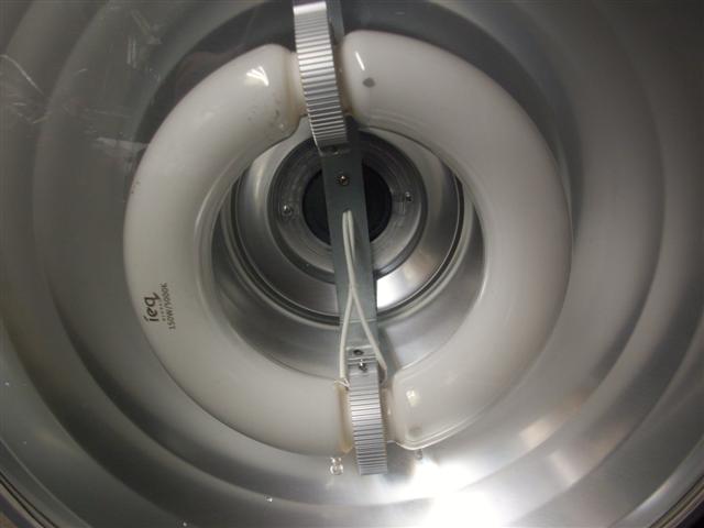
Figure 1 - Induction Lamp And Drive Coils
Since the lamp is in most respects virtually identical to a traditional fluorescent tube, it shares the same type of phosphors, uses a small amount of mercury (although in an amalgam rather than liquid mercury), and emits some ultraviolet light. As noted above, there is also a significant heat output, however this is easily isolated from the electronics module and does not cause significant lumen depreciation (the loss of light over time). Because of the high frequency drive system, there is no flicker at all. Unlike discharge lamps (metal halide, sodium/mercury vapour), the induction lamp strikes (illuminates) almost instantly, and can be switched off and back on again with no delay. This is a major benefit for critical lighting applications, where the loss of light for several minutes (as is the case with discharge lamps) cannot be tolerated. Most high intensity discharge (HID) lamps cannot be re-lit until they have cooled down.
There is concern in some circles about the electromagnetic radiation (EMR) created by the induction system. While this might be a legitimate issue with lamps used at close range, this is not the way these tubes are normally used. They are much too bright to have too close to a work surface, and when used for their most appropriate functions (large area lighting) radiation is not expected to be a great concern. Remember that CFLs and T5 fluorescent tubes also operate at a relatively high frequency too, but still much lower than the 130kHz - 260kHz range I've measured for the induction lamps tested.
In all other respects, induction lamps can be compared with standard fluorescent lamps. Colour temperature, phosphor types and CRI will all be very similar to what we are used to with normal fluorescent tubes. As such, you can ignore (or avoid) sites that claim CRI is better than a standard fluorescent lamp - they use the same phosphors, but fail to explain how any 'improvement' comes about. Consider it to be marketing spin - sounds good, but has no basis in reality.
The biggest difference between induction and conventional fluorescent lamps is power and light output. While luminous efficacy is not quite as good as the latest T5 tubes with electronic ballast (or so it's claimed in some descriptions), these lamps have much higher power ratings. Around 60W seems to be the lower useful limit (I have seen as low as 15W claimed, for sale direct from China). The two I tested were both rated at 150W, and the upper limit seems to be around 400W at present.
There is little or no information available, but there are a (small) few manufacturers who claim their induction lamps are dimmable. In reality, this is probably not a viable option with these lights. While it might be possible, there's probably not much point given the primary applications for induction lamps. Where dimming is available, it is to be expected that it will be over a limited range, as with all other fluorescent lamps. Dimming is not really suited to any fluorescent lamp - including 'dimmable' CFLs (I have two, and they are useless).
It is obvious that instant re-start, lack of electrodes or heaters to erode away and fail, and very high light output are great strengths. Although I've not tested it, induction lamps also apparently work just fine in very cold environments, although it will take a little longer for the tube to reach maximum brightness. It doesn't seem to be mentioned anywhere that just like an ordinary fluorescent tube, light output increases as the lamp heats up - it's not as dramatic as with CFLs, but it happens nonetheless.
Weaknesses are never discussed by those who want to sell their product, but they obviously exist. As mentioned earlier, heat and UV radiation may be issues in some environments, although the heat output is probably about the same as other discharge tubes of comparable power, or even high power LEDs. Provided the heat from the tube itself is kept away from the electronics (the 'ballast' or power supply) it isn't likely to be a major issue. Electromagnetic radiation is unlikely to cause a problem, but it does exist and can be picked up easily by an external coil (that's how I measured the drive frequency!).
Another issue is that the light is omni-directional. The only way to get all the light from the tube to do useful work is to provide a very efficient reflector, but these simply don't last. A 'perfect' reflector will be seriously degraded over time, as dust and condensation start to coat the surface. All manner of other airborne particulates (smoke being particularly effective) will degrade the reflector, so while the lamp may well be providing as much light as it did when (almost) new, the light output from the luminaire can easily be halved - just from reflector contamination.
UV radiation is usually not a serious concern for most applications, and should not normally be any greater than that generated by other discharge lamps. However, most of those selling these lamps don't even mention it. Nor do they mention EMR or mercury, although given the expected life of the tube, the latter is unlikely to cause great concern. It's apparently less than used in a traditional fluorescent tube.
Some specialised lamps such as the xenon arc and metal halide have little chance of being replaced in the near future. While their ultimate efficiency may be lacking by comparison, they will continue to be used for many specific applications. One of their major advantages (and one that cannot be reproduced with induction lamps) is the very small light source. This is essential for applications where the light beam needs to be focussed, such as in projectors, pin spotlights, and similar other lighting with similar requirements.
By direct comparison, the single most important limitation of LEDs is their operating temperature. The light emitting junction should remain below 85°C, although there are some that have been optimised for higher temperatures. This limitation does not apply to induction lighting systems, so large heatsinks are not needed. This is a big plus, because the heatsink needs to be physically large (and expensive) to maintain a sensible junction temperature.
As described above, the tube has no electrodes or external connections. This eliminates the most troublesome part of any discharge lamp. The high frequency induction coils transfer energy from the outside of the tube to the mostly inert gas inside, creating a discharge that vaporises some of the mercury held in the amalgam.
Once the arc is 'struck', intense ultraviolet (UV) light is created by the mercury arc, and this excites the phosphors on the inside of the tube. In this respect, operation is the same as a traditional fluorescent tube. The lack of electrodes ensures the very long life of the tube. Induction lamps come in two different types - internal coil and external coil. These are shown below.
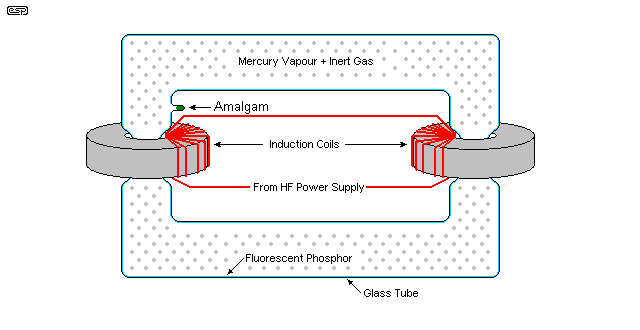
Figure 2 - Induction Lamp, External Coil
The external coil type is claimed to have a longer life, but I've not been able to find any information that explains the reason. Those I tested included one of each type, but I expect that my popularity would be affected if I destroyed either of the lamps trying to dismantle it. I did try (of course), but stopped when I encountered serious resistance to my attempts to get the internal coil lamp apart.
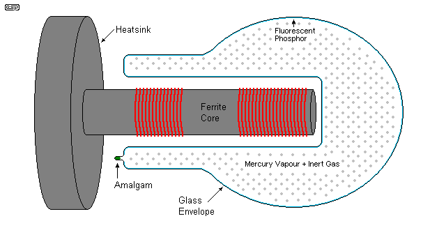
Figure 3 - Induction Lamp, Internal Coil
In general, the internal coil type has slightly lower luminous efficacy. This is easily understood, because the inner section of the lamp where the coil is located emits light, but only a portion of that will escape into the great beyond. A percentage is therefore lost, so overall lumens will be reduced for a given power rating.
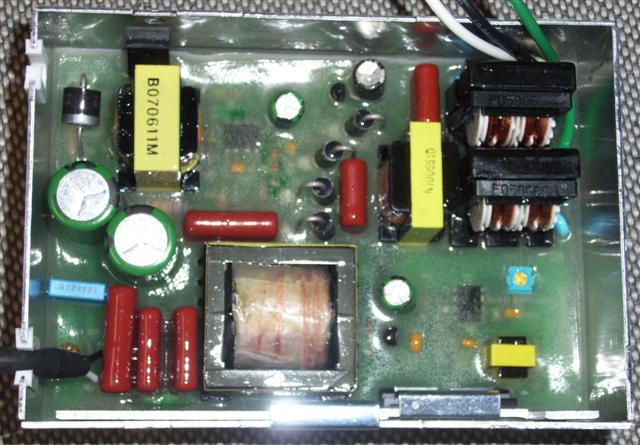
Figure 4 - Induction Lamp "Ballast"
There was one rather intriguing claim that I saw while researching this article. It was stated that the Chinese have simply copied old Philips and Osram ballast designs from 20 years ago, and these do not come up to modern 'digital' standards. WTF? This is complete nonsense - verging on word salad, and I doubt that it was ever the case. Certainly, those I tested have a very good power factor, low harmonic currents and high efficiency. The ballast shown in Figure 3 is a modern Chinese design, but it's unfortunately been potted in epoxy so I can't reverse engineer the circuit.
The principle of operation is straightforward enough though. The designs will all typically have a fully electronic power factor correction (PFC) circuit, which takes the rectified (but unsmoothed) mains, and produces a constant 350V DC (typical) supply. This is then used to power a resonant switching circuit that produces a current-limited high frequency signal to the induction coil(s).
The block diagram of a typical power supply ("ballast") is shown in Figure 5. Although I've only seen two of these lamps thus far, I expect that all quality units will have very similar circuitry. Almost all high power supplies for LED lighting have active PFC, and it's now something that is expected - it's no longer considered a 'luxury', because many countries either have, or are planning, to make PFC mandatory for lighting power supplies exceeding perhaps 50W. Indeed, even 15W LED tube-lights and other fittings are now using active PFC. It used to be very complex, but ICs now exist that make it far more sensible than attempting to struggle by without any power factor correction. Something that only a few years ago was difficult and expensive, is now close to being cheaper than a conventional rectifier-capacitor power supply, has far fewer problems with meeting worldwide standards, and provides a 'grid friendly' load to the mains supply network.
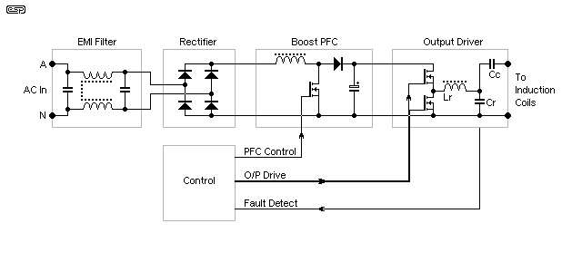
Figure 5 - Induction Lamp Power Supply (Block Diagram)
The above is a general representation of the power supply ("ballast") used to drive induction lamps. The power factor correction circuit won't be discussed in detail here, as there is a great deal of information on the Net about how they work. Suffice to say that the PFC circuit draws a current from the mains that is essentially a sinewave. There is usually some deviation, and that results in some current waveform distortion. Provided the distortion is below 10%, the power factor will generally be better than 0.9 (unity is ideal).
The output stage is intended to provide a sinewave signal at the selected frequency (say 250kHz), but may still be a simple squarewave switching power supply. The output circuit (Lr and Cr) must be tuned to get resonance at the desired frequency. The switching MOSFETs usually only need to conduct for a part of the output waveform allowing for high efficiency and low losses. The resonant output circuit is designed to filter out the harmonics and produce a reasonably clean sinewave output. The combination of Cc (coupling capacitor) and the lamp's induction coil also forms a resonant circuit.
So far, I've not been able to get my hands on a complete circuit diagram, so I'm a little in the dark as to specific details - and I have no desire to reinvent the wheel, as it were. I will update this page as soon as I can provide more information on the resonant output stage. I know that it's resonant, because I can see a fairly clean sinewave (with some switching 'artifacts') on the waveform collected by my pickup coil.
Tiger Light Provided the sample induction lamps that I've measured. Otherwise, there are few references as such, because much of the data are derived from direct measurements. Product photos are from lamps dismembered in my workshop between measurements.
Some of the figures quoted for induction lamps were obtained from Wikipedia and from a few (rather sparse for the most part) manufacturer data sheets.
 Main Index
 Lamps & Energy Index
| Copyright Notice. This material, including but not limited to all text and diagrams, is the intellectual property of Rod Elliott, and is © 2011. Reproduction or re-publication by any means whatsoever, whether electronic, mechanical or electro-mechanical, is strictly prohibited under International Copyright laws. The author (Rod Elliott) grants the reader the right to use this information for personal use only, and further allows that one (1) copy may be made for reference. Commercial use in whole or in part is prohibited without express written authorisation from Rod Elliott. |