

|
| Elliott Sound Products | Spark Quench Circuits |
 Clocks Index
 Main Index
Please note that the techniques described here are intended for coils or solenoids that operate from a low (less than 12V) DC supply. Although few clocks other than mains synchronous types use AC, it is possible that there are some mechanisms that use low voltage AC - especially for solenoids. Do not apply any of these methods to an AC solenoid unless you know for certain that it will work, and never use any of these techniques for mains powered solenoids.
Almost all of the early electric clocks used a crude resistor in parallel with the coil. The modern equivalent is a diode (and some battery electric clocks from the 1960/70s used diodes). This purpose of the spark quench device is generally puzzling for the clock enthusiasts, because of the lack of detailed knowledge of electrical circuits and what they do when power is applied or removed. This is very much to be expected, as the whole process is not exactly intuitive. While there is a vast amount on information on the Net that covers spark quench circuits, it's not at all easy to determine if what you are looking at is relevant or even accurate. There is a great deal of drivel from people who seem to think they know the answers, but don't have a clue.
Many clock collectors will have several battery powered clocks in their collections, and this trend will continue because some of the earlier battery clocks are now highly collectable. Examples include Bulle, Brillé, Eureka, etc. In almost all cases, a contact arrangement makes and breaks the circuit to the actuating coil, and this is the process that we will investigate here. It's surprisingly important information to know, because if the wrong decision is made you can adversely affect battery life, your contacts, or even the coil's insulation.
In the early days, even some of those who made the clocks didn't know a great deal about electricity and magnetism, but they quickly learned that if you apply current to a coil then break the current flow abruptly (as with a pair of contacts), you get a high voltage which causes a small spark. This spark can cause accelerated contact erosion, and can even cause insulation failure within the coil or other wiring. This may seem very puzzling, since most of these clocks were operated from a 1.5V dry cell (typically zinc-carbon or similar chemistry).
How can you get a spark (and an electric shock if you happen to be holding the wires to the coil) from 1.5V? Quite clearly, there is something strange going on which may be deeply mystifying if this isn't something you've been working with all your life. The answer is simple, but requires a good understanding of the relationship between electrical current and magnetism.
A coil is what is generally known (in electrical terms) as a reactive device - one that stores energy. A coil stores its energy by way of a magnetic field ... as long as current flows through the coil, a magnetic field is created within and around the coil, and it is this field that provides the impulse to drive the pendulum, or to operate a solenoid to reset a gravity arm or remontoire mechanism. When the electrical current is stopped, the magnetic field collapses. The main property of any coil is called inductance, which is measured in Henrys (don't ask).  )
)
The collapse of the magnetic field is almost instantaneous, and as it decays to zero, a voltage is generated in the coil that was an electro-magnet just moments ago. Most people will know that if you wave a magnet near a coil, a voltage is developed, and the voltage is proportional to the number of turns of wire, the strength of the magnet and the rate of change of the magnetic field. If the rate of change is very high, a high voltage will be generated, even in a coil with comparatively few turns. This may still be somewhat mystifying, but any attempt to provide a complete explanation along with diagrams would simply take up too many words, and isn't especially important. One term you may have heard is 'back EMF' - that is exactly the issue we are looking at here.
What is important is that you accept that it does indeed happen, and that it has to be stopped to prevent problems in the clock. What we see as a problem is the basis of one of the longest lived inventions of the modern age - the Kettering ignition coil used in millions of motor vehicles world wide. There are also countless other electronic circuits that rely on these same principles.
In many cases, the induced voltage (the back EMF) might be lower than expected. This can be caused by losses in the magnetic core, a brass casing around the coil (which acts as a shorted turn and drains the energy quite quickly), or other factors including the coil geometry. In theory, there is no reason that a coil can't deliver a back EMF of many thousands of volts, but this will not happen in practice because insulation will fail before the theoretical maximum can be achieved. Even the arc itself damps the peak voltage, because it converts the energy stored in the coil into heat. All fascinating stuff, but fortunately it's not necessary to fully understand it all to know how to prevent the back EMF from causing problems.
Having established the basic principles, we can now direct our attention to looking at how effective the solution really is. The diagrams below show the results of actual measurements of the coil pictured. I can state with certainty that all coils behave in exactly the way described. There are many variables that change the duration of the pulses or cause other anomalies, but the principles are identical. Indeed, any two coils will show different behaviour unless they are absolutely identical in every respect, so variations are perfectly normal. The following is a photograph of the coil I used, and the screenshots are taken from my oscilloscope - actual captured waveforms from a real coil.
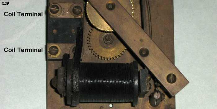
Figure 1 - The Coil Used For The Tests Described
This coil and rather battered movement are part of an old Synchronome type slave movement, but this one is badly worn and the index/ratchet wheel is damaged. The coil is still fine though, and the armature functions normally. Measured resistance was 14.5 ohms, and the inductance was measured at about 2 Henrys. Inductance is the property of a coil that makes it reactive. It's not important to understand it, but is is important to know that it exists. The coil was powered with a mere 3V for all test waveforms shown below. Coil current was therefore just over 200mA ...
Current = Voltage / Resistance
Current = 3 / 14.5 = 0.207A, or 200mA close enough
There was no particular reason for choosing this coil, other than that it was the first one I found out of several that I have lurking around in my workshop. Any other coil will produce identical effects, although current will be different, as will coil resistance and back EMF. This is of no consequence - we are looking at the effects and how they occur, rather than specific numbers.
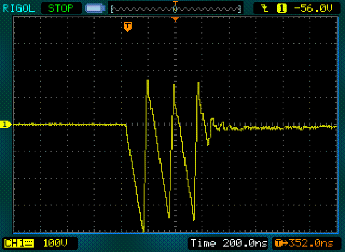
Figure 2 - Coil Voltage With No Spark Suppression
Each vertical division on the screen is 100V, and each horizontal division is 200ns (200E-9 second, or 200 billionths of a second ... yes, really). When the current is switched off (you can't even see the +3V before the main signal), the voltage jumps very quickly to -400V, then up to +170V, back down to -350V, etc. Everything is over in less than 1us (one millionth of a second). Without a fast digital oscilloscope, this kind of signal is almost impossible to see on a normal analogue 'scope screen unless you are lucky. After ~800ns, the disturbance is completely over, and the voltage across the coil is almost zero.
The problem is the 400V impulse signal. It can be a great deal more, and had I tried a few more times I would probably have been able to measure 1,000V (1kV) or more. During previous tests, I've seen spikes that were well over 1kV. It is this high voltage that causes the spark that you see when unsuppressed contacts open.
The fact that the voltage waveform is not just a simple negative spike is not always so easily explained, because there are several separate things that happen all at once. These transitions are caused mainly by an imperfect contact break (which is almost all of the time). As the contacts open, there are multiple momentary disconnections before the molecular structure of the contact materials finally stops current flow. This happens both when contacts open and close, and is massively worse with sliding contacts. Although it looks nasty, it causes no harm to a typical clock coil after suppression is applied.
There is also the arc (since no suppression was used, an arc is assured). I am unable to predict or postulate on the effects of the arc, other than that it will have unexpected and variable consequences. Any arc will cause heat, and this will help to dissipate the energy stored in the coil. It will also remove a microscopic amount of contact material. This, coupled with the imperfect breaking action of almost all contacts, can cause the waveform to vary considerably from what we might imagine should be the case. The above was one of the cleanest waveforms I captured, believe it or not.
To understand the final reason requires a good knowledge of resonant circuits. Suffice to say that a pendulum is a resonant circuit (albeit mechanical), and requires two main ingredients ... mass (equivalent to electrical inductance) and a restoring force (electrical capacitance). Capacitance exists in any electrical circuit when any two conductors are close to each other, but not making electrical contact. The multiple turns of wire in the coil all exhibit a tiny amount of capacitance between each turn and its neighbour - even though they are connected! The end result (without including a complete chapter just on this topic), is that the coil has what's generally known as self-resonance (the inductance and the 'stray' capacitance), and that causes the rapidly diminishing transitions that you see at the very end the above waveform. We can calculate the frequency from the oscilloscope trace (or get the oscilloscope to calculate it for us), but there's little point.
The 'oscillation' is real, it does happen as shown, it will be different almost every time the contacts open, and we don't really care. We do care about the high voltage, as this can erode contacts by sparking, or even cause insulation failure in the coil. Remember that in many cases the clock may be over 100 years old, and electrical insulation materials back then were mediocre at best. The traditional method used to suppress the high voltage and quench the arc is covered next.
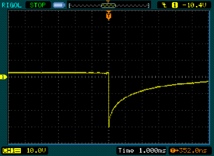
Figure 3 - Coil Voltage With Resistor Spark Suppression
This time, I connected a 150 ohm resistor in parallel with the coil, directly across the two terminals. This was a common 'rule of thumb' at the time these clocks were made ... use a resistor that's 10 times the resistance of the coil. It's not a bad compromise, and in theory (again, rule of thumb), if the spark quench resistor is 10 times the coil resistance, the back EMF will be 10 times the applied voltage. Likewise, if the resistor is 5 times the coil resistance, the back EMF will be limited to 5 times the applied DC voltage (and so on).
The oscilloscope settings are shown - vertical is 10V per division, and horizontal is 1ms per division. This time, you can see the +3V applied to the coil, and when the circuit is broken the back EMF is (surprise, surprise) -30V. Not only is the voltage reduced dramatically, but the time taken for the circuit to settle back to normal is also extended. Where the unsuppressed coil had zero volts across it in less than a millionth of a second, with the resistor connected it hasn't quite reached zero even after 6ms (6 thousandths of a second). It actually takes almost 10ms before the voltage has fallen to zero. This also extends the duration of the magnetic impulse, albeit only by a small amount.
As you can see, the resistor works quite well, but it does use some additional power. This becomes important when the only power source is a very expensive cell - that was the only choice for the early battery clocks.
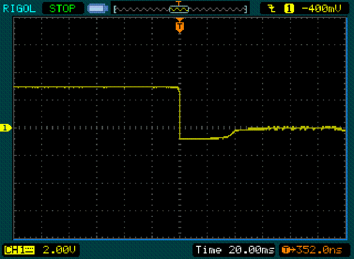
Figure 4 - Coil Voltage With Diode Spark Suppression
Finally, a diode was used to completely suppress the back EMF. Once the current is interrupted, the maximum back EMF voltage is ~0.8V, and this is a huge improvement. However, there's a downside that can have very unexpected results with some clocks. Look at the horizontal timebase - each division is 20ms, and now it takes just under 40ms before the back EMF is dissipated and the voltage returns to zero.
This means that the coil still has a significant magnetic 'pull for almost 40ms more than would be the case if no suppression were used, and it's easily 30ms longer than when a resistor is used. This extra time (even though rather short by the standards of most people) can cause some clocks to suffer a small disturbance that may affect timekeeping. It can also be used to advantage in some cases, because a shorter contact closure can result in the same magnetic pull duration.
A diode has another potentially undesirable effect though. Some clocks don't care which lead is positive and which is negative - they will work perfectly well regardless of polarity (the Synchronome is a good example). Once diodes are added, if the power supply or battery is connected the wrong way around, it will be short-circuited by the diode when the contacts close. This will damage the diode or the power supply, or quite possibly both. The clock (or slave) is no longer bipolar - the supply must always be connected the right way around to prevent damage.
Zener diodes (which have a defined breakdown voltage) work well, but also need a series diode or a second zener (see schematics below). As with any diode based solution, polarity is fixed if you use a single zener and a normal diode, so there is a defined positive and negative terminal on a clock coil that may have been polarity insensitive when made. For this reason, use of two zeners connected back-to-back is a better solution, as it is not polarity sensitive and will work regardless of the supply polarity. Note that the zeners must have a higher breakdown voltage than the applied voltage, preferably no less than double the battery or power supply.
Sometimes, you may hear that a capacitor can be used across a coil to suppress the arc. Basically, this is a bad idea, because it can have several effects, none of which is very useful. A small capacitance will easily allow the full peak voltage to be developed (I measured -400V for a test I conducted), so transient voltage suppression is minimal at best, useless at worst. If you use a large value of capacitor, the transient voltage will be reduced, but there is a very high current drawn when the contacts close. With a large capacitor and a low resistance circuit, the peak current is limited only by the resistance of the contacts, power source and connecting wires. This current may be so high that it causes the contacts to weld closed - hardly very useful or desirable.
Capacitive 'spark suppressors' (generally in conjunction with a resistor) are often suggested, and while they do quench sparks across the contacts, they do nothing to reduce the impulse voltage. The potential for insulation damage is just as great as if the capacitor/resistor combination were not present at all. These spark-quench circuits are usually connected across the contacts, not the coil.
Metal Oxide Varistors (MOVs) look appealing, but they are not readily available in low enough voltage ratings. While a suitable MOV will limit the voltage spikes they are far more expensive than resistors, and offer no real advantages. They may be found to be suitable in some cases, but their breakdown voltage is not well defined.
There are a couple of other possibilities, but I won't bother detailing them because the devices are somewhat esoteric and there is simply no need. Most of the time, a resistor is all you ever need, but a full review of the more common methods is shown below.
The resistor suppression system works very well, and is very simple. Although the rule of thumb says the resistor should be 10 times the coil resistance, it can be more or less if you prefer. In general, higher resistance may not be a good idea (the peak voltage will be greater), but a lower resistance will work fine if current drain is not a problem. However, there are other methods as described above, and the range is shown in Figure 5. There are several more combinations that can be applied if you know exactly what you want to achieve.
The little waveform graphs above each circuit are to give you an idea of the voltages you are likely to encounter, and are based on the test coil that I used. They are not to scale, but are simple representations of what you will see on an oscilloscope if you have access to one and want to run some tests. Your results will be different, but the same trends will be readily apparent.
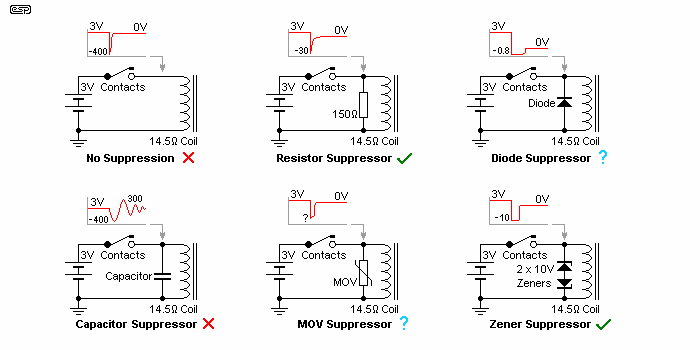
Figure 5 - Spark Suppression Schematics & Waveforms
Needless to say, a red cross means that the scheme is not recommended, and a green tick means that it's a good method. A question mark simply means that suitability is subject to test and experimentation - it may work very well, or may be a complete failure. Both the resistor and zener diode techniques are well defined, and both will work very well indeed. If a 30V zeners are used, the performance will be almost identical to the resistor, but with zero power loss while the coil is energised. However, it's marginally more expensive (still no more than $1 or so though) and if two zeners are wired back-to-back as shown, the electrical circuit is not polarity sensitive. The zener voltage should be selected to be between 3 and 10 times the applied DC voltage. The zener voltage must always be greater than the battery or power supply voltage.
If a diode or zener diode scheme is used, I suggest 1N4004 diodes and 1W zener diodes. Both are very common and easily obtained, and will never be stressed to anywhere near their limits even with a substantial coil such as the one I used for testing. While lower power parts can be used (the back EMF can never exceed the zener voltage), these parts are so cheap and so common that it's not worth trying to find anything smaller or cheaper. Indeed, smaller parts may even cost more.
One thing that is certain to cause clock people (and even many electronics people) trouble is working out the power requirements for the resistor. This is made harder because a lot of very early clocks used large coils of resistance wire rather than the resistors (as components) that we know now. These didn't exist until some time in the 1920s, and even then there was little or no communication between those who worked with 'wireless' and the clock fraternity. Seeing these today is likely to have people thinking that considerable power is involved, but this is not the case at all.
Finding a large wire-wound resistor (but one that no longer works for whatever reason) is bound to make most people think that it needs to dissipate lots of power, or withstand high voltages, or both! The 150 ohm resistor I used for the above example will dissipate 60mW with 3V across it permanently, but it will dissipate 6W for a few microseconds. After only 1ms the power has fallen to 1W. The most common carbon or metal film resistor can withstand that with ease - especially since it only needs to dissipate power for perhaps a couple of milliseconds every 30s (for a Synchronome). The maximum voltage (30V) is also well within the ratings of common parts - very few resistors will fail at such a low voltage.
The resistor doesn't need to be able to withstand 400V or more, because its presence ensures that 400V spikes never happen. So, if you were to choose a 1W resistor (a commonly available size, and very cheap) it will work perfectly, and will last almost forever - accidents excepted of course. If you wanted to, there is no reason not to use a 5W wirewound resistor (they are still pretty cheap), but they are physically much larger and will be more difficult to hide away (since they look nothing like the original resistors which are unobtainable). The same calculations can be done for any combination of coil resistance and external resistor with any voltage. How do we work out the resistor power?
Power = Voltage² / Resistance
P = 3² / 150 = 0.06W (60mW) continuous
P = 30² / 150 = 6W momentary
Remember, that the 3V case above is for continuous voltage, but this is almost never the case with clocks. Even under fault conditions where the operating voltage is applied continuously, the resistor will handle it with ease. The peak (momentary) power rating can never last for any length of time, and it's not necessary to allow for the full peak dissipation.
I mentioned above that the resistor uses additional power. While this is unimportant for a clock that relies on the mains and pulls perhaps 200mA or more, it's more of a concern for 'power miser' designs such as the Bulle or Brillé. The coil resistance for a Bulle is typically around 1,000 to 1,200 ohms, so with 1.5V the coil will only draw around 1.4mA worst case. If a 10k resistor is added in parallel with the coil, this will draw an additional 0.15mA - not much, but cell life will be reduced by 10%. Naturally, if a lower value resistor is used, the extra current will be higher and cell life reduced accordingly.
Exceeding the 10:1 ratio is not really recommended, because of the extra voltage that will be generated. Note that with high resistance coils typical of many clocks, the resistor power is negligible when power is applied, and the smallest resistor you can find is suitable - even when dissipating the back EMF. For example, a 10k resistor fitted to a Bulle clock will dissipate a peak power of 22mW for a few microseconds. When power is applied to the coil, it will dissipate a mere 225uW (225 millionths of a Watt).
One final point that needs to be made ... many clocks have a coil that swings over a magnet, so if you decide to add a resistor to the coil, make sure that the leads are non-magnetic. Some resistors use a steel alloy for the leads (cheaper than copper), and if this is mounted on a coil that swings over a magnet (or where the magnet swings over or through the coil), the steel will play havoc with the pendulum swing. I've seen this happen, and it goes without saying that timekeeping isn't improved as a result. It's quite surprising how easily a tiny piece of steel can disturb the swing of a relatively heavy pendulum.
 Clocks Index
 Main Index