
|
|
| Elliott Sound Products | Demagnetiser |
 Main Index
Clocks Index
Main Index
Clocks Index
While magnetised tools can be useful, they are a disaster when working with clocks or watches that use a hairspring regulated balance. A magnetised hairspring will almost always stop a watch or carriage clock, and any other clock can stop if the magnetism is strong enough and interferes with the normal operation of the clock.
Most demagnetisers rely on the operator knowing that it is essential to move the item being demagnetised well away from the demagnetising coil before power is removed. In general, I suggest a minimum of a good arm's length distance between the two. Anything sitting on the bench next to the demagnetiser is likely to become magnetised when the button is released, so this is generally a tool that almost requires its own corner of the workshop to prevent undesired outcomes.
To be useful, a demagnetiser needs to be quite powerful, but this normally means that heavy current would be drawn from the mains, and because of the low frequency (50 or 60Hz), it takes a while to demagnetise anything. The big advantage of the unit described here is that it is very fast, yet far more powerful than most commercial units. To top it off, it doesn't get hot either, and it won't melt if you forget to switch it off.
The process of demagnetising a tool or anything else is straightforward. The item is subjected to an intense magnetic field that reverses polarity and diminishes to zero over a period of time. While it's not appropriate to attempt to explain the effects in the metal to any great degree, suffice to say that the process described pushes magnetic 'domains' in the metal one way, then the other, but a little less each time. The net result is that the item is demagnetised - provided power wasn't interrupted until the object was far enough away from the demagnetising tool that the magnetic field is close to zero.
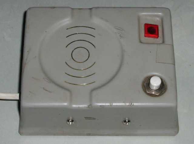
Photo Of (Old) Commercial Demagnetiser
Most demagnetisers just use a coil and a switch, and while this is usually effective, it requires knowledge on the part of the operator, and the on-time must be kept brief to prevent the unit from overheating. Many demagnetisers will not tolerate being on for more than a few seconds before they get rather hot, and they have to be allowed to cool between operations. Units that can be left on for extended periods are usually fairly feeble, and may not even be able to demagnetise some tools.
The demagnetiser described here uses a different method, and it works very well indeed. It may be described as a ringing-choke or resonant coil demagnetiser, and it uses the stored charge in a capacitor to operate. Once triggered, the coil current alternates between positive and negative with a decaying waveform that is perfect for demagnetising. The unit pictured below is a commercial offering, but there is no information anywhere that says who made it, where it was made or anything else. That it works is not in any doubt, although it's a little disconcerting at first. When the button is pressed, the whole process takes about 50ms (0.05 second), and most larger tools will twitch quite violently. Power to the coil is much higher than you might expect - it will normally start at around 15A or more, and diminishes to zero within 50ms. Because the pulse is so brief, the unit can be used once every minute or so, and probably all day if you wanted to.
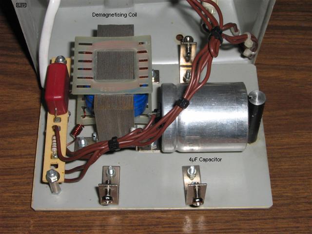
Figure 1 - Commercial Demagnetiser Inside
The circuit is quite straightforward, and is shown below. The 4µF capacitor is charged to over 600V, taking less than 5 second to reach full charge. When pressed, the 'DEMAG' switch first disconnects the charge circuit, then connects the coil directly across the 4µF capacitor. The waveform across the coil is shown below. Note that the original design has no power switch, no safety earth connection, and no fuse. All of these are needed for safety and protection against electrical faults. The demagnetisation process takes less than 1/10 of a second!

Figure 2 - Commercial Demagnetiser Schematic
There are a couple of critical parts in this design. The input capacitor (470nF, 275V~) must be what's known as an 'X' class cap, designed to withstand the full mains voltage. The second cap (4µF) has a fairly hard life, and should be a motor start or power factor correction capacitor. It is expected to discharge a high current and withstand a high voltage, and for that it needs to be very rugged. As you can see from the photo above, the cap is physically quite large, at 40mm diameter x 50mm long (excluding mounting post or terminals).
The switch needs to be at least mains rated, as it too is subjected to the full discharge current when it's pressed. By today's standards, there are a few additions that need to be made to the circuit, as it is somewhat unsafe as shown. In particular, there is no resistor to discharge the 470nF cap. After the unit is unplugged, the user could get a substantial shock from the mains plug pins. Unlikely to be lethal, but very unpleasant and quite unexpected.
The combination of C1, C2, D1 and D2 is a voltage doubler rectifier. With 230V AC applied, the voltage across C2 will reach over 600V within about 5 seconds. Mains input current is limited primarily by C1, although R1 also helps a little. Pressing the button disconnects the charge circuit, and joins C2 (4µF) directly in parallel with the coil. This creates a damped oscillation between the coil and capacitor, as shown below.
Internally, the 4µF cap stores a charge that is extremely dangerous, and is perfectly capable of killing anyone who pulls the unit apart without realising what's inside. There are no warnings, and the charge could be held for a considerable time (days to weeks!). To prevent this, the cap in the unit shown above appears to have an internal discharge resistor (as does the new one shown below). The discharge is relatively slow, but the voltage can be considered 'safe' after about 90 seconds.
Figure 3 - Coil Voltage When Button Is Pressed
Above, you can see the voltage waveform when the button is pressed. The full voltage stored in the capacitor is connected to the coil, and the energy oscillates back and forth between the two until it is finally dissipated as heat. The primary cause of energy loss is the resistance of the coil, however this is not a problem because we want a diminishing oscillation, just like the one we see above. As the voltage and current falls with time, so does the magnetic field - exactly the requirement for demagnetisation. The Q of the circuit needs to be high enough that we get a fairly long ringing time, so coil resistance must be minimised. The oscillation frequency is determined by the capacitance of C2 and the inductance of the coil. My unit (described below) oscillates at 860Hz. The frequency can be calculated if you know the exact values of C2 and the coil ...
f = 2π × √( L × C ) Where L is the coil inductance and C is capacitance in Farads
f = 2π × √( 6.8mH × 5µF ) = 863Hz (close enough)
Note that the unit described is designed for 220-240V operation, and I have no information about 120V versions, or even if they exist. To obtain the same charge with the circuit as shown, the coil must have a very low resistance, and the 4µF capacitor must be increased to 16µF because the voltage will reach a maximum of only about 320V. Otherwise, the circuitry would be virtually identical (although charge time will be longer unless the 470nF cap is also increased). An alternative is to use a 120V to 230-240V step-up transformer and keep the circuitry the same. The step-up transformer does not have to be high power - the maximum current drawn only around 30mA, indicating a transformer of no more than 10VA is needed.
This is not something that I encourage anyone to try unless they have good skills with mains powered electrical devices. There is considerable risk involved, and you will need to be able to wind the coil and connect mains powered components together in a competent and safe manner. Because of the high voltage and the storage capacity of the capacitor, this is a potentially lethal project. One small error could lead to death or serious injury, so should you decide to build one, you do so having acknowledged that ESP provides this material for information only, and that your decision to build the device is yours alone. All risk and liability is accepted by the intending builder.
 | WARNING: This circuit requires experience with mains wiring. Do not attempt construction unless experienced and capable. Death or serious injury may result from incorrect wiring. |
Although the circuit looks to be almost trivial, it's not, and will cheerfully kill you if you aren't paying attention. The main capacitor (C2) must be discharged before you touch anything inside the unit. It may be capable of storing a lethal charge for days or weeks. Although these caps have an internal discharge resistor, you should still do the following ...
To discharge C2, disconnect the demagnetiser from the mains (don't just switch it off - disconnect it !), then press the DEMAG button and hold for a couple of seconds. Check that the cap is discharged by joining the terminals together with a screwdriver blade (while you hold the plastic handle). Then, and only then, may you work on the unit as needed. The process described must be followed every time the unit has been powered before you work on it. Most motor-start or power factor correction caps will have an internal bleed resistor to prevent them from retaining a charge indefinitely, but don't count on it. Where internal bleed resistors are fitted, they will not discharge the capacitor quickly, and may cause complacency - this is a bad thing to mix with high voltages.

Figure 4 - Modified Demagnetiser With Safety Additions
The first additions are the mains switch and fuse. The original had neither, so the unit was permanently powered as long as it was plugged in, and had no protection if there was a component failure. R1 has been added to discharge C1 so that anyone contacting the mains plug pins will not get a shock when the demagnetiser is unplugged. R1 is specified as 1W, not because of power dissipation but to minimise voltage stress across the resistive element. The core of the demagnetising coil should be connected to earth (ground), along with any metalwork on the case itself. Note that the case must be made from plastic or other non-conducting material (for example, fibreglass or timber). You need access to the area directly above the coil, and any material here needs to be non-conducting, as thin as possible, but still strong enough to ensure that no-one can puncture it easily to gain access to the circuitry.
A major nuisance was the DEMAG switch. A robust single-pole, double-throw (SPDT) push-button could not be obtained readily, so rather than searching countless catalogues and ordering one in, I located a centre-off rocker switch. Although I originally thought that it would be pretty useless, I realised that it gave me the option of selecting the demagnetising charge (the switch is shown in Figure 8, and has a CHG and ZAP label). I'd still prefer a normal SPDT push button, but the new arrangement works well enough for the time being. Get the push button if you can, and wire it as shown in Figure 4. With the wiring shown, the second neon lamp (NE2) will light in proportion to the voltage across C2.
Winding the coil is likely to be a pain, for several reasons. Firstly, the transformer needs to be the right size, and has to be pulled apart. Some are so heavily varnished that it is extremely difficult to separate the laminations for dismantling, but varnish can be softened with paint stripper if necessary. Whether the bobbin remains usable is another matter, but all wire must be discarded. While it may be tempting to just use the existing secondary of a mains transformer (after rearranging the laminations as shown below), the primary winding must be removed. If you don't remove the primary, when the coil is pulsed you could easily get several thousand volts across the open circuit winding (remember, the coil is pulsed with over 600V). This is likely to cause insulation failure which will prevent the demagnetiser from working properly (if at all), and may also pose an immediate threat to your longevity ... in other words it could easily kill you!

Figure 5 - Dismantled Transformer To Make New Coil
A major challenge for many people will be finding a transformer that is not only the right size, but can also be dismantled without having to resort to an angle grinder or 200 tonne hydraulic press. The above transformer was not especially hard to get apart, and you can see that the primary winding is partially removed. This will be replaced with 0.8mm wire (the same as the existing secondary), and the two windings connected in series so they behave as one. The completed coil is shown below, after it was reassembled. Ensure that you have as many turns of wire as will fit into the bobbin, but do not use thin wire!
The laminations shown are 22mm (measured on the centre leg of the 'E'), and this is a rather good size. Aim for something between 15-25mm for most applications. The original demagnetiser has a centre leg of about 16mm. The new coil has a total inductance of about 6mH, and a DC resistance of 0.87 ohm (both windings in series). The original secondary is on the top, with the new winding below. The two windings are in series, and must be wired for maximum inductance. If one winding opposes the other, the pulse will be very weak, so try it both ways. The correct polarity of the windings will be immediately apparent when you get it right.
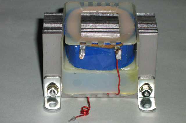
Figure 6 - New Demagnetiser Coil
The main discharge capacitor must withstand high voltage, and a high current waveform that includes polarity reversals. These all place considerable stress on the capacitor, so it needs to be selected to be able to withstand the voltage and current it will experience in use. A capacitor rated for 400V AC will most likely be fine for the job, and the most rugged types are generally those used for motor start and/or power factor correction. Do not use a polarised electrolytic capacitor, because the polarity reversals during ringing will ruin it. At this stage, I don't how long the one I purchased will last, but it's the best I could find at the time. Of particular importance is the internal impedance of the capacitor. It must be low, or the oscillating waveform will die away too quickly.
The remainder of the circuit is assembled on tag board, standoff insulators or similar, as shown below or in the original. Do not use Veroboard or other material with punched holes and copper strips, because the spacing between copper sections is too narrow for the voltages required. There are relatively few parts, so construction is not difficult. While neon lamps with built-in resistors are shown in the schematic, some neon lamps may not have the resistor - if this is the case separate external resistors must be added.

Figure 7 - New Demagnetiser Chassis
The capacitor, coil and remaining parts are wired onto the earthed aluminium chassis, and the cover just needs closing in the above photo. I used a piece of un-etched PCB material for the cap bracket and wiring - all unwanted copper was removed with a Dremel, and clearance needs to be at least 5mm between live connections and chassis. Since I really dislike attached power leads, I included an IEC mains connector so the mains lead can be removed for storage. The power switch is on the back next to the connector. Remember that everything inside the box is connected directly to the mains, so great care is needed whenever the cover is off. Initial tests are very promising - it seems to work just as well as the original. Making the cover was a challenge though - it's hardly worth making up a blow-moulding pattern for one item, and I have no intention of making any more of these demagnetisers.
As you can see, the inside of the case is pretty packed. There is only just enough room for everything, and this unit was complicated by the IEC mains connector and the odd arrangement I had to use for the switch. The internal wiring is identical to the schematic shown in Figure 4.
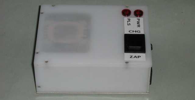
Figure 8 - Completed Demagnetiser
Making a one-off case for a project such as this is a real challenge. It must be strong and safe, because of the high voltage within. The top has to be thin, but then there is no easy way to attach it to the sides or support the switch. Eventually, I decided on an acrylic case, and a section is milled internally to accept the top of the coil. The remaining plastic after milling is about 0.75mm thick, and the coil is adjusted so that it presses firmly on the thin top section. The base is aluminium, and is connected to mains earth (ground), as is the coil's laminated core.
Having gone to all this trouble, is it actually worth the effort? In a word ... yes. This is one of the best demagnetisers I've used. It's very fast and leaves very little measurable residual magnetism. I have been told that this type of demagnetiser can be used on a watch hairspring without ending up with a tangled mess, but I've not verified this. The string of pulses is so fast that the hairspring shouldn't have time to tie itself into a knot. This is a unique property of the unit described, and is shared by no other that I'm aware of.
As noted, there seems to be a complete lack of information on the Net or elsewhere that I have found, so it is possible that there may be an in-force patent of all or part of the circuit. This is highly unlikely, as I believe it's well over 20 years old. Any patent that happened to exist now would not be enforceable.
Main Index
Clocks Index