

|
| Elliott Sound Products | Practical DIY Waveguides - Part 3 |
 )
) Main Index
 Articles Index

Please Note: A number of people have told me that this series of articles contains errors. I do not dispute this, but I will point out that it is a contributed article, and I never had access to most of the references cited. Some formulae appear to be incorrect (or may lack clarity). I have not been able to contact the original author, so I don't have the resources to make corrections. The general principles are sound, and it's probable that anyone intending to build their own can do so without needing to make all the calculations shown.
I apologise for the inconvenience of presenting an 'incomplete' article, but I've decided that it's better to keep the article (with caveats) than to remove it. There is still some very useful information in the three articles, and (IMO) this outweighs the fact that it contains errors and omissions. I apologise in advance for any inconvenience this may cause, but I do hope that readers will find the information useful (at least in terms of general principles).
The driver is a Vifa D25AG-35-06, this is chosen as a typical good quality dome tweeter that in addition has extra flexibility due to a low fs, (the one used is unfortunately a 'Tymphany' branded one that has a high fs, and generally inferior performance to the pre-Tymphany types).
The frequency response as measured on Speaker Workshop is as follows ...
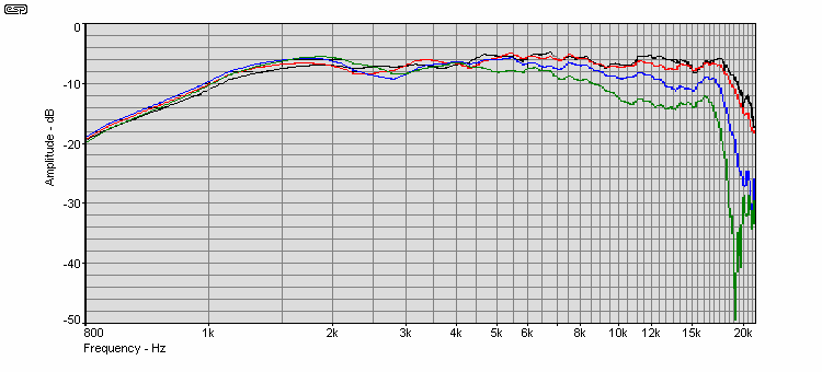
Figure 17 - Vifa D25AG-35-06 Frequency Response, On Axis, 15, 30, 45° Of Axis
This driver is suitable for 250mm (10") and 2.5 way 200mm (8") systems, theory suggests up to +6dB output can be obtained by waveguide loading thus allowing a lower crossover frequency for the same diaphragm excursion. If we make angle α = 90° ...
c = ( 720 + 90 ) / 5 = 162
b = 360 - 324 + 90 = 126
w = 1 / 3 × (( 25,306 (126 × 162 + 90 × 162 + 90 × 126 )) / ( 1500 × 90 × 126 × 162) = 142mm
Where w is the width (diameter) of the waveguide mouth. The horn radius is ...
r = (( w - t ) / 2 ) / sin ( α / 2 )
... where t is throat diameter and α is the radiation angle. Throat diameter is determined by the tweeter used, and must be measured carefully. The overall depth is ...
d = r - (tan α / 2) (( w - t ) / 2 )
The radius at points x is ...
r ( x ) = ( t / 2 + ( w - t ) / 2 ) - ( r² - ( m + x )² ) ½
... where m = Tan α / 2 ( 0.5w - 0.5t ) and t = throat diameter. x is the centreline distance along the waveguide from the throat in millimetres.

Figure 18 - Waveguide Drawing
| x | r | x | r | x | r | x | r |
| 0 | 18.5 | 6 | 25.2 | 12 | 34 | 18 | 47 |
| 1 | 19.5 | 7 | 26.5 | 13 | 35.7 | 19 | 50 |
| 2 | 20.6 | 8 | 27.8 | 14 | 37.6 | 20 | 54 |
| 3 | 21.7 | 9 | 29.2 | 15 | 39.7 | 21 | 59 |
| 4 | 22.8 | 10 | 30.7 | 16 | 42 | 22 | 71 |
| 5 | 23.9 | 11 | 32.3 | 17 | 44 |
In the above, d is the depth of the conical section, dt is the total depth and r is the radius of the mouth flare. Provided that the constructor has an eye for such things, it is probable that a satisfactory test unit can be turned on a lathe with only a few basic calculations - the total width, total depth and throat diameter. With a good 'eye' for curved surfaces, the radiused section can almost certainly be turned purely by eye and a finger test to ensure that the transition from conical to flared sections is completely smooth and free of discontinuities.
The method of turning on a lathe is the obvious method of making axis symmetrical waveguides. In the case of non axis-symmetrical devices this presents a problem so I decided to experiment with 'plug' moulds and polymer clay moulding compounds, since this was easily adaptable to non axis-symmetric types. The use of a plug mould allows great accuracy in form since a simple template made from aluminium sheet is all that is needed. This can be used as a forming tool as well as a template.
There are many different types of polymer clay that may be used. These are generally available from craft shops, although you may need to search to find a supplier handy to you. While many of these compounds are designed for (or at least packaged to appeal to) children, they are very useful materials in their own right. A web search for "polymer clay" (include the quotes) will be the quickest way to find a suitable material. The finished product is shown in figure 18 ...
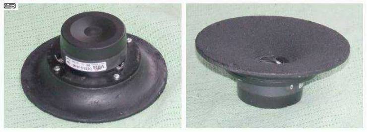
Figure 19 - Finished Waveguide and Tweeter Assembly
The plug mould to make the waveguide is made by gluing hardboard discs in a stack of the correct height and approximate profile using a central hole for reference. A mixture of sand and PVA glue is then used to roughly form the profile with the help of a template. The mould is then finished with building plaster or similar, and coated with PVA glue then sanded smooth. When thoroughly dry, paint with several coats of flat black enamel. In use, don't forget to use a release agent to prevent the mould and waveguide from becoming permanently attached to each other. The makers of the moulding compound you use will recommend a suitable release agent in the instructions.
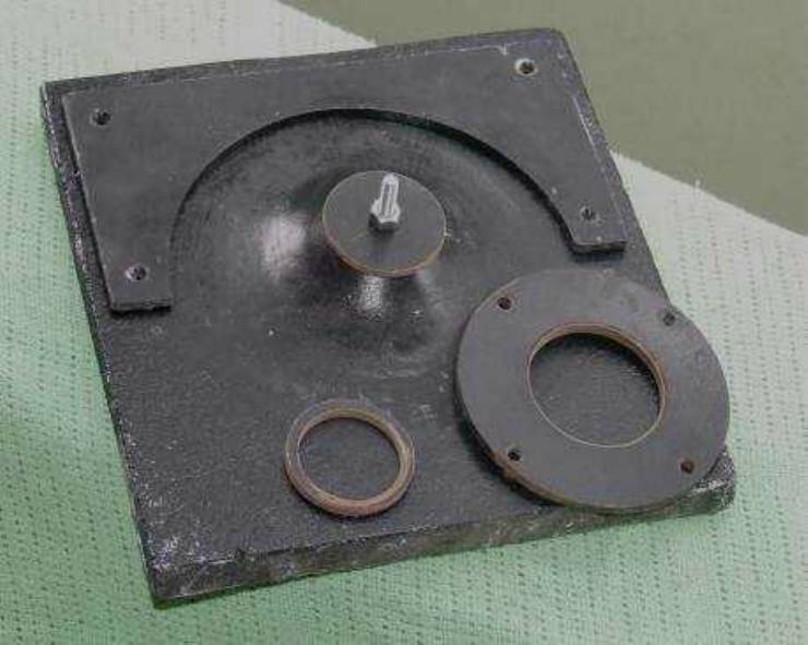
Figure 20 - Waveguide Mould
The tweeter mounting ring and throat piece are also shown, the other piece is the flange moulding piece, this is screwed on to the base and is split for easy waveguide removal. The moulding surfaces are coated in petroleum jelly (or as recommended) as a release agent.
As theory predicts, the output is flat to the drivers mass corner and then rolls off at a first order rate. Since the effective driver efficiency is increased by 4-5dB in the region before the mass corner, this roll off can be compensated for by a simple RC parallel network. The effective excursion limited power handling is increased by the same amount (i.e. 4-5dB) in this region.
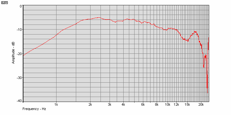
Figure 21 - 1.5kHz Waveguide On Axis, No Equalisation

Figure 22 - Equalisation Circuit
The 18 Ohm resistor (R2) is optional. It helps to ensure that the crossover network sees a relatively constant impedance across the crossover frequency range.

Figure 23 - On Axis, 15, 30 and 45° Off Axis of Waveguide With Equalisation
The driver now has flat frequency response within ±2dB from on axis to 45° off axis. Both power and frequency response are flat, i.e. constant directivity.
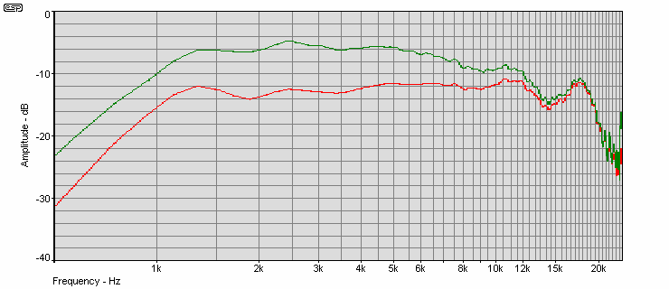
Figure 24 - Comparison of Equalised and Non Equalised On-Axis Response
Figure 23 compares the FFT spectrum of the raw driver (red), and waveguide harmonic distortion with 1.5kHz input signal. The level was adjusted so the input to the raw driver was 2.45V RMS into 6Ω (the Vifa tweeter is rated at 6 Ohms), and the output adjusted to achieve the same SPL with the waveguide and compensation network in place.
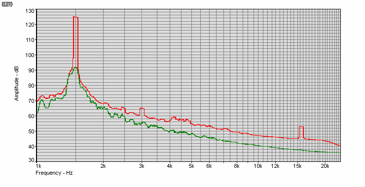
Figure 25 - FFT 1.5kHz Input Sinewave ... Red = Raw Driver, Green = Waveguide Plus Equalisation
There is a definite reduction in THD, as is quite obvious from the above.

Figure 26 - FFT Spectrum 1.6kHz & 12kHz Tones, 4:1 Ratio
Figure 27 shows a two tone IMD (intermodulation distortion) test using 1.6kHz and 12kHz at a 4:1 amplitude ratio, The red plot is the raw driver, the green plot is tweeter driver including EQ and waveguide.
The RightMark Audio Analyser (see Web Site) program gives THD = 0.32%, IMD = 1.45% for the waveguide, and THD = 0.39% and IMD = 1.6% for the raw tweeter. The input levels for this test were lower than for the previous measurements.
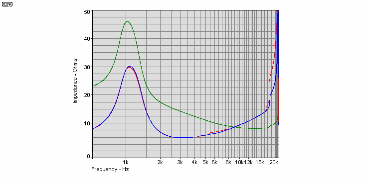
Figure 27 - Comparison of Raw Driver (Green), Equalised (Red) and Equalized Waveguide (Blue) Impedance
The impedance plot shows none of the sharp discontinuities that are usually found in horns - these are caused by standing waves. As is, the waveguide is suitable for biamping, a convenient feature of this type of equaliser is that you can get the overall impedance nearly flat and suitable for standard passive crossover components by shunting the input with an 18 Ohm resistor as shown Figure 22.
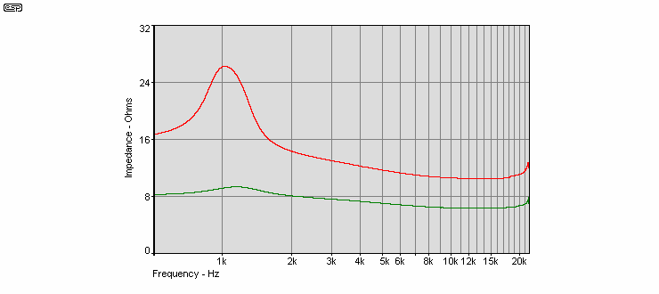
Figure 28 - Impedance of Equalised Driver with 18 Ohm Parallel Resistor at Input
From the tests I have done, I can conclude that the method outlined can produce a constant directivity device that has lower distortion and better power handling than the original driver alone, and there are no measurable results that would indicate the presence of 'horn sound'.
This particular waveguide is the simplest one since the tweeter used has a phase plate incorporated into its mounting plate, and in this waveguide the tweeter is screwed to the waveguide as is, no modifications to the tweeter being performed. If you are not sure about modifying the tweeter in any way this is the best option. I do however have data that suggests there is advantage in removing the phase plate and a 3kHz waveguide of this sort was described in Part 2.
 Main Index
 Articles Index