
 |
| Elliott Sound Products | Acoustic Centre |
 Main Index Main Index  Articles Index Articles Index |
The acoustic centre of a loudspeaker is the point in space from which sound waves appear to originate. When adjacent loudspeakers (typically mid-bass and tweeter) are not aligned properly, there is often a notch at the crossover frequency. The sound-field is not projected forwards as is wanted, but is at an angle determined by the offset. The tweeter's output will be 'first' as it's generally closer to the listener. The mid-bass driver follows some time later (usually a few 10s of microseconds), so there's a lobe aimed at the floor instead of at your ears. It's this lobe that causes the frequency response dip, because the speaker's energy isn't directed where you want it (to your ears). It shows up as a dip in the frequency response when that's measured on the tweeter's axis (the most common measurement technique).
The issue with most driver combinations that people use is that their acoustic centres are different. Dedicated dome midrange drivers might manage a very small effective offset, but when a dome (or ribbon) tweeter is use in conjunction with a cone mid-bass driver, there's effectively a delay in series with the midrange driver. It's only a short delay (perhaps from 50 to 100μs), but it can cause response anomalies. These may not be audible, but a measurement system will show any issues.
This can be corrected in a number of ways, with one common approach being to include a phase-shift network (all-pass filter) in series with the tweeter to delay its output. This is easily done with an active crossover, but is more difficult when passive networks are used. Sometimes, designers will use asymmetrical crossovers (e.g. 12dB/ octave low pass and 18dB/ octave high pass), and while this can provide almost perfect response when applied correctly, it's not without challenges. Perfecting the design is not a simple process. A graphical example is shown in Fig. 4.3.
With the advent of DSP (digital signal processing) systems, it's usually possible to introduce a digital delay to align the drivers, and there are systems that will do everything for you, based on a series of measurements. These are outside the scope of this article, not just because I'm an 'analogue man', but also because adding DSP is a serious undertaking. There are 'cheap and cheerful' DSP systems (although they aren't cheap any more), but a great many of my crossover PCB sales are to people who have a cheap DSP and discovered the limitations thereof.
Physical displacement will also work, which can be due to a 'stepped' baffle (so the tweeter is moved back so the acoustic centres align), a sloping baffle (which means you are slightly off-axis for all drivers), or by using a waveguide for the tweeter which can both move it backwards and improve efficiency. Waveguides come with their own set of problems of course, not the least of which is designing it so it doesn't impact on the tweeter's response.
This article examines a number of different techniques that you can use to locate the AC of a pair of drivers. It's likely (based on the test methods described below) that all will give a slightly different result, so it's up to the constructor to decide on a method that s/he's happy with. Each method has its merits and drawbacks, with some being somewhat irksome to set up (and I know this because I had to test every technique described). Much depends on your workshop facilities, and your level of determination.
The hard part is knowing where the acoustic centre of a driver is, and knowing how to find it. Ideally there should be no highly specialised hardware or software needed, but you will need a microphone (electret or a dynamic type). This is easy and cheap, because it doesn't need to be perfect, and off-the-shelf cheap electret mics will work just fine. If you have an electret capsule, you only need a 5V DC supply and a 10k resistor from the supply to the mic's positive (the case is ground/ common). No capacitor is needed because the scope can be set for AC coupling to remove the DC offset.
Any electret mic will be sufficiently flat across the crossover frequency band (usually between 1kHz and 4kHz). Even if it doesn't have flat response, the results will still be fine. This is because you are looking for the delay between the application of a pulse and the time taken for it to reach the microphone. Since you're not trying to measure frequency response, any electret will work. A dynamic mic can be used, but it will also have an acoustic centre too. This will be a constant though, and it just adds a bit to the overall time-of-flight (ToF) of the test signal.
The first (and biggest) problem faced when determining the acoustic centre offset is where do you take the measurement? You can measure directly in front of each driver, but then there will be an offset when you listen to the speakers. This depends on how close you are as well, since in the near-field a small difference in listening position (vertical) will cause a difference in the path length from the driver to your ears.
There are countless methods suggested to determine the acoustic centres (AC) of drivers, all different, and most are likely to give slightly different results. Using a pulse (in my case, a single cycle of a 3kHz sinewave repeated at 1s intervals or a transient created by discharging a capacitor into the speaker) look as though they should give good results, and when performing measurements the results seem to be pretty accurate. You can also use an impulse generated by audio test software and base the measurement on that.
One suggestion from the late J Marshall Leach (sorry, I have no reference for this) was (apparently' to 'assume' the acoustic centres to be at the peak of a dome tweeter and the point where the dustcap meets the cone for a woofer. It's easy and convenient, but my tests indicate that this is likely to be fairly close. Is it close enough? That's for you to decide, based on your expectations.
I took a bunch of measurements, and everything makes a difference. A good result was obtained with the mic directly above the centreline of each driver, and time the arrival of the pulse measured using a scope. By triggering from the electrical signal, the time-of-flight (ToF) was easily measured. When the ToF for each driver was identical (same time delay, about 508μs) the drivers are time aligned. It turns out for those I tested that the acoustic centre offset is between 38mm and 27mm. That means that the mid-bass driver has to be (on average) 32mm closer to the listener than the tweeter - that's not a huge offset, but it poses a challenge.
Sound travels at roughly 0.343mm/μs, so a ToF difference of 100μs means that one signal had to travel an extra 34mm compared to the other. A 'conventional' flush-mounted tweeter will almost always present its signal first, so it has to be delayed so its AC is the same as that from the mid-bass (or midrange) driver.
Unfortunately, the AC of a driver is not a fixed quantity, and it can vary with frequency. Provided it remains fairly constant for one octave above and below the xover frequency, the results will be satisfactory. Only rigorous testing will provide all the information you need, tempered by reality (speakers are rarely even close to flat response devices) and your expectations. If you expect the response to be within ±0.5dB you will be disappointed. Even 'top-shelf' speakers will typically show an overall response that's no better than ±3dB (unsmoothed). Some are better, but not many (often the results are 'doctored' by applying excessive smoothing).
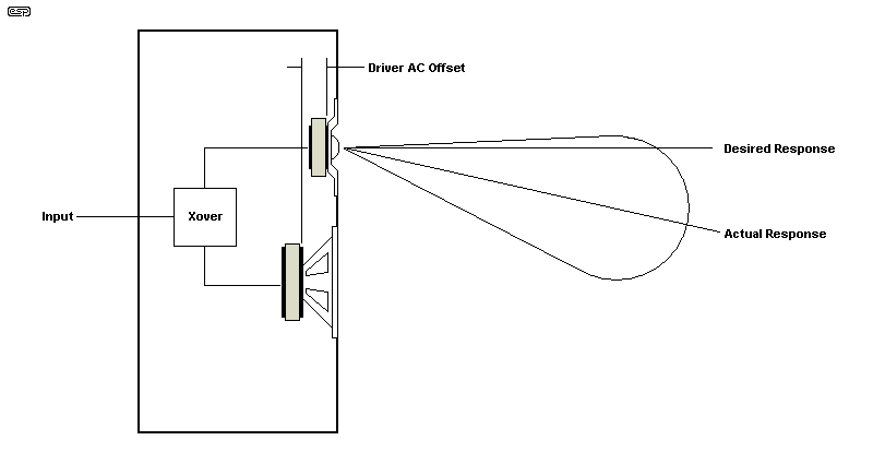
The lobe created by the tweeter signal arriving first is shown above. This only occurs at (or near) the crossover frequency, where both drivers are providing the same signal, but with different phase relationships due to physical displacement. Above and below this frequency range, each driver is independent. In this drawing (along with those that follow), I've assumed the listening position is on-axis for the tweeter.
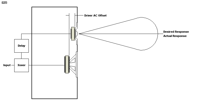
A 'true' delay is difficult without a DSP, but a reasonable delay can be achieved using one or more phase shift networks (aka all-pass filters). These are designed to operate at a lower frequency than the nominal 90° frequency, and the delay is what's known as group delay. It's generally fairly easy to obtain a group delay of up to 40μs (13.7mm offset). This is covered in detail in the article Phase Correction - Myth or Magic.
An ideal delay circuit will give flat group delay to at least one octave but preferably two above the crossover frequency (±2μs or so). For small offsets this is easy (up to 50μs 917mm] or so). It becomes more difficult if you need a greater delay with additional all-pass filter stages.
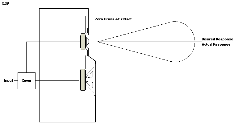
Stepped baffles are often frowned upon because if not executed properly you can create a 'diffraction engine' that will create more problems than it solves. However, it's been done by many respected designers/ manufacturers, and it solves the problem very nicely. It should be obvious that you need to know the difference between the acoustic centres before starting work on the cabinet! I recently saw an article that examined the diffraction effects in some detail, but I've not been able to locate it again. The conclusion was that diffraction is not usually an issue, provided the step is modest (up to perhaps 25mm or so).

One way I tested was to wire the two drivers in parallel, with attenuation to the tweeter to get roughly equal levels. Each driver has a switch so it can be turned on or off. When the woofer and tweeter are switched, if the drivers are time aligned, the signal will arrive at the same time (and polarity).
When both drivers are enabled, the level should increase if the two signals are in-phase. Adjust the relative spacing to get the maximum increase. At close range (200mm), if you go off-axis for the tweeter, the timing will change because the relative distances change. Ideally, the mic should be at least one metre away, but that may prove to be difficult due to the low level picked up by the mic.
However, this will give an incorrect result because the path from the mid-bass is longer (relatively) than it will be when you're listening (unless you listen at 250mm - somewhat unlikely). The reason is based on simple geometry.
If the mic is 200mm from the tweeter, the distance to the midrange is 228mm, but as you move out further, the error is reduced from 14% to 1.7% (at 600mm). At greater distances the error is reduced even more, but once it's below 1% there's unlikely to be much real improvement. The error will be greater if the drivers are farther apart. This is Pythagoras' theorem in action.
When two identical signals are summed passively, with a pair of resistors, the output is equal to the voltage from either source. When the phase relationship is unequal, we see an overall phase shift and a reduction of level. For example, two 1V sources at any given frequency will provide a 1V output. We'll assume 3kHz for simplicity.
Should the phase of one be shifted by 10°, the overall amplitude will fall by 0.044dB and the signal will be shifted by 4.8μs. Increase the phase shift to 20°, and the amplitude drops by 0.13dB, with the signal shifted by 9.6μs. A further shift to 30° cause the amplitude to fall by 0.31dB, with a displacement of 14.4μs. With 45° shift the level drops by 0.7dB (close enough).
Most readers should know that if the phase is shifted by 90° the amplitude falls by 3dB. What you likely don't realise is that the effective time advance or delay is 43.2μs. This in itself is mot important, but it becomes relevant when you look at loudspeaker drivers. Determining the acoustic centre offset is as much about the phase relationship of the driver (i.e. is it inductive, resistive or capacitive at the frequency of interest.
We would normally hope that it's resistive, but in reality that's unlikely. I used an impedance bridge to determine the impedance and phase angle (at 3kHz) for the two drivers I tested (as shown below). Unfortunately, few hobbyists have access to such an instrument, so consider the data to be moderately interesting, but irrelevant for the most part. It can be determined by other means, but it's not as useful at it might seem. I also used Dayton Audio's DATS to measure the impedance and phase of the mid-bass and tweeter.
Driver Impedance (3kHz) Reactance Tweeter 6 Ω 2.5° Capacitive Mid-bass 11.75 Ω 35° Inductive
The tweeter is benign, with its nominal and measured impedance being identical. The mid-bass is a different matter, being inductive and with a phase angle of 35°. That means that the current lags the voltage, so the output (which depends on voicecoil current) will be delayed by about 32μs (equivalent to a mechanical displacement of about 11mm). This shifts the acoustic centre back from its assumed position. However, as discussed above, a 30° phase angle causes a very small error, so it's not likely to be a problem.
The physical offset will be far more significant than the phase displacement caused by the voicecoil's inductance. Effective capacitance is created by the driver's compliance, and the mechanical analogue of inductance is mass. The variable impedance and phase angle of the voicecoil current explains (at least in part) why the AC varies with frequency.
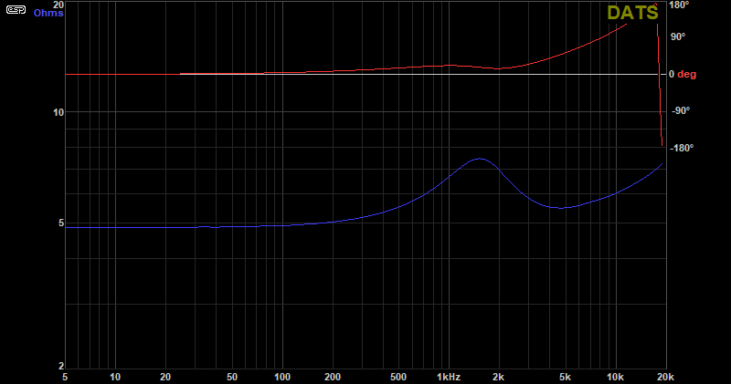
This measurement is a little different from those I got with the impedance analyser, but is still (potentially) useful. Resonance is shown clearly, and because it's quite flat that indicates that the tweeter is very well damped. It only increases to ~7.5Ω from the nominal impedance of 6Ω. Below resonance you just see the voicecoil's DC resistance. I added a cursor line at the 0° phase point for both graphs.
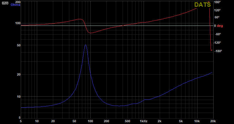
The mid-bass is inductive above 500Hz (actually semi-inductive). When looking at any impedance graph, if you see the impedance rising with frequency the load is inductive. Conversely, if the impedance falls with increasing frequency the load is capacitive. A resistive load remains constant with frequency. The mid-bass driver is resistive at two frequencies - resonance (800Hz) and between 300Hz and 400z.
On this basis, using the top plate of the magnet assembly looks like a fair compromise. At 32mm (vs. the measured difference of 29mm) that's an error that will have a negligible impact. Interestingly, during the tests I discovered that one mid-bass I tested was reverse-phase, so a positive input produced a negative initial output. This was not expected! The next drawing shows the general scheme for any speaker, and it's shown as a mid-bass unit. Tweeters use very similar construction, but without the cone.
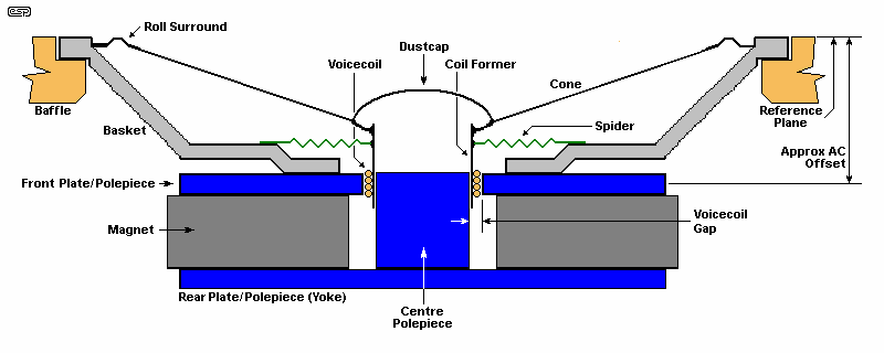
It seems sensible to assume that the middle of the top plate/ polepiece is the source of the sound. After all, it's all down to the movement of the voicecoil, and that is centred in the gap between the top plate and centre polepiece. Of course, it takes time for any movement to propagate along the voicecoil former and activate the cone (the parts are not 'infinitely stiff'), but is this significant? Based on physical measurements and electro-acoustic measurements, the answer seems to be "maybe". Even getting an accurate physical measurement isn't always easy, because with tweeters in particular, the top plate is often embedded (or at least partly) into the plastic 'basket' and it may be difficult to locate its centre-line. In most cases its approximate location can be found with a little guesswork.
In each case here, I've assumed flush mounting which is generally preferred to minimise diffraction. That's why I've taken the front of the driver surround as the 'reference plane'. If you surface mount the drivers (not recessed into the baffle), then the reference point is the rear of the mounting flange.
I've seen a lot of different schemes suggested over the years Some of these are magnificently over-complicated, to the point where mere mortals will probably mutter a few choice phrases and move along. As the old saying goes though "for every complex question, there is an answer that is obvious, easy to understand, and wrong".¹ I like to stay away from these if I can, but sometimes an apparent over-simplification can still result in an answer that's 'good enough'. In the context of audio reproduction, there are so many influences that can affect what you hear that perfection is not possible. If you use a simplified technique to estimate the AC offset that happens to be a few microseconds in error, the acoustical deviation will (hopefully) be less than the normal response variations of the drivers used.
If you happen to be out by (say) 10μs (3.43mm) the level may be affected by up to 0.5dB at the crossover frequency. Not perfect, but room effects can have up to an order of magnitude more effect, and even the speaker drivers themselves are far less accurate overall. Of course, you can verify the results by measurement, and the results may surprise you. After all, the loudspeaker system is the weakest link in any audio chain - everything else is typically way ahead in terms of response flatness, distortion and transient response. Of course, you're reading this because you want to make your speakers as good as possible - never a bad thing.
¹ Adapted from H. L. Mencken
The numbers shown are all at 3kHz, and while they may change with frequency, it's not by a great deal. I've only shown the measurements for the mid-bass and tweeter at 3kHz, with the time taken from the peak of the electrical pulse and the peak of the acoustical pulse. I tested a high-quality mid-bass (ScanSpeak Revelator 120mm), and my electro-acoustical measurement gave an offset of about 28.5mm, and the distance from the reference point to the magnet's top plate measured 27mm. 1.5mm offset is negligible and it can safely be ignored. The tests described here were performed on a 'no-name' but quite passable 120mm driver.
I found that a mic at roughly 10mm from the mounting plane of the driver (I'll call this the reference point) works fairly well, but it's not overly critical - provided you keep the distance consistent for all tests. The mic must be on the driver's axis. I tested at 1kHz, 2kHz, 3kHz and 4kHz, ensuring that the signal arrived at the same time in each case. With a distance of 11mm (set by the spacer I used) between the reference point of the driver and the mic, the minimum possible time delay is about 32μs, which is easy to display on a scope. If the driver's acoustic centre is (say) 10mm behind the reference point, you'll measure a total time delay of 61.2μs (21mm total distance).
λ = C / f (where λ is wavelength, C is velocity [343m/s] and f is frequency) d = t × 0.343 t = d / 0.343 So (for example) ... d = 20 × 0.343 = 6.86 (mm) t = 6.86 / 0.343 = 20 (μs)
Sound will travel 0.343mm in 1μs, based on the nominal 343m/s speed of sound at 20°C. Of course it changes with temperature, but 343m/s remains a reasonable estimate. In a number of articles I've assumed 345m/s. but the difference is tiny. The time is in microseconds, so if you measure 20μs it's entered in the formula as '20'. Likewise, distance is in millimetres, so 6.86mm is entered as '6.86'. If you include the suffixes in the formula you'll get very silly answers.
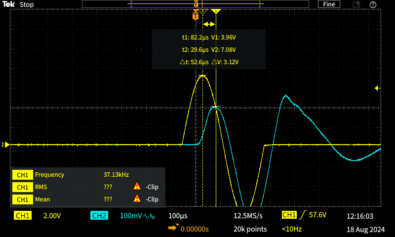
As with the mid-bass, there's a little ambiguity, and the measured tweeter time offset is ~53μs determined by the peak amplitude of the electrical and acoustic signals. Although the 11mm is included, the error is the same in both cases, so the offset remains unchanged. I didn't go to the trouble of subtracting the 11mm 'extra' delay, and you don't need to - it doesn't affect the relative offset.
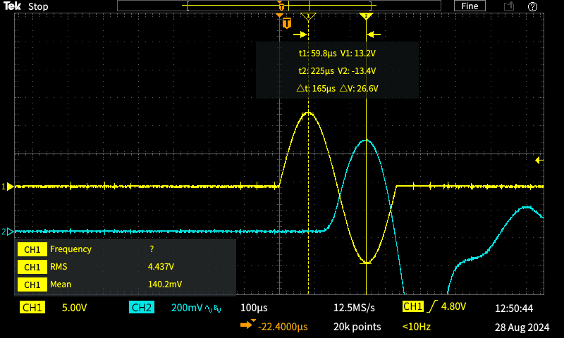
With any electromagnetic system there is some ambiguity as to where the pulse really starts. I tried the zero-crossing, but found that the peak is (probably) more accurate. The following table shows the measured offsets using ToF (time of flight) with a pulse, the measurement from the mounting plane (front of faceplate/ mounting flange) and from the mounting plane to the top of the dome and dustcap attachment point (the tested mid-bass has an extra 3mm above the mounting plane). As is pretty obvious, the latter is not even close to the real offset.
I didn't test (or run any calculations) for this next point, but it might be worth looking at more closely. There is some inertia in the voicecoil/ cone assembly, and perhaps measuring the timing of the second peak (negative-going) may be more realistic. Music can never generate impulses as fast as the one I used, but with good motors I'd expect that most speakers will respond as hoped-for after the initial half-cycle. My personal view is that the technique described is probably correct, but without a dedicated test enclosure specifically for the drivers being tested this can't be proven either way.
Driver Time of Flight Distance -11mm Spacer Top Plates Dome/Dustcap Tweeter 53 μs 18 mm 7.01 mm 10.5 mm 0.8 mm Mid-bass 165 μs 56.6 mm 45.6 mm 40 mm 28 mm Relative Offset 112.4 μs 38.5 mm 38.6 mm 29.5 mm 27.2mm
The average of the measurements shown is close enough to 32mm (we can ignore the fractional part), and the deviation is not excessive. I'd consider it to be well within acceptable limits, so you can use any of the techniques without fear of any major issues with overall response. Considering that probably most home-built (and many 'name brand' speakers) will have made little or no adjustment for AC offset, I expect that an offset of around 30mm (roughly 87μs) will be very satisfactory. It doesn't matter if the delay is engineered by using a stepped baffle, digital delay, phase shift network or an asymmetrical crossover, the end result should be pretty flat response across the crossover region.
Should the difference between the acoustic centres be much greater, it will be harder to deal with. The wavelength at 3kHz is C/f, or 343m/s / 3k - 114mm. A half-wavelength is 57mm, so if there's a 57mm AC offset that would put the drivers out-of-phase at 3kHz. Reversing the phase of the tweeter will (in theory) re-establish time alignment, but it's very frequency dependent. This method is only recommended if you use a 24dB/octave crossover. The fast rolloff minimises errors caused by the relative timing.
It's (at least somewhat) noteworthy that if the delay caused by the mid-bass voicecoil inductance (about 32μs or 11mm) is subtracted from the measured ToF derived as shown, the offset is reduced to 27mm, very close to the distance between the magnet top plates. This was already measured at about 35° and is more-or-less benign. I'm fairly confident that alignment of the top plates will give a result that's satisfactory for any loudspeaker design. The room and cabinet edge diffraction will almost certainly have a far greater effect than a 35° phase misalignment.
The second method you can use doesn't require a tone-burst generator, but just uses a capacitor (around 33μF) charged to 12V via a 2.2k resistor. The cap is discharged into the voicecoil with a bounce-free switch (so-called mini tactile switches are as good as you'll get). The scope is triggered by the electrical pulse (the yellow trace in the screen captures below). The mic output is captured on the other channel.
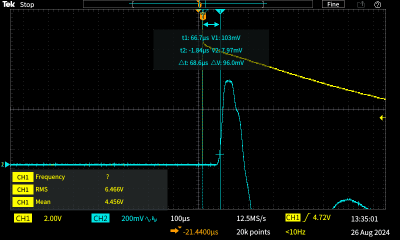
The delay is 68.6μs, taken just as the signal rises (roughly 10% of the peak amplitude). As before, the mic was spaced from the mounting plane by 11mm. It's interesting that the tweeter and the mid-bass give shorter times with this technique. The offset is roughly half that indicated with a single-cycle tone burst. While it may be tempting to use the peak of the mic signal, this is unlikely to be accurate. However, it is fairly close to the ToF obtained with the tone burst.
If you were to use the peak as the ToF reference, you get about 120μs for the tweeter and 240μs for the mid-bass. The difference is 120μs (41mm), and is not far from the figure determined using the tone-burst method (112μs). The distance difference is negligible.
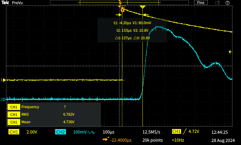
The mid-bass/ woofer's delay is 137μs with the same 11mm spacing from the mounting plane. The difference between this and the tweeter is close enough to 69μs, an equivalent distance of 24mm. This is quite different from the effective displacement determined using the tone burst. Which one is right? Unfortunately, the only way to be certain is to mount the drivers on a baffle and perform a frequency response measurement. My gut feeling is that the 'real' figure is probably halfway between the two. That works out to 16mm (a bit under 47μs).
Driver Time of Flight Distance Tweeter 68.6 μs 18.01 mm Mid-bass 137 μs 41.16 mm Relative Offset 68.4 μs 23.5 mm
Interestingly, this is pretty close to the previous methods. On the basis of these tests, I'd be pretty happy to acoustically align the top plates of the two drivers and use that as the acoustic offset. Everything is a compromise, but aligning the top plates (either mechanically or acoustically) is likely going to give a fairly consistent result. After all, this is where the voicecoil is located, and that is the origin of the sound that's propagated by any loudspeaker. This is by far the easiest measurement to take (it requires nothing more than a ruler). However, there is a delay due to voicecoil inductance, but provided the phase shift is less than ~45° I wouldn't worry about it too much.
The most accurate measurement may end up being to use both drivers in parallel, with one driver phase-reversed. You then look for the deepest notch with a sinewave at the intended crossover frequency. When the acoustical signal is perfectly cancelled, the phase angle is 180°, and the test is extremely sensitive to the smallest phase change. Unlike testing for flat response (where ±30° only makes a tiny difference), a notch is sensitive to only a few degrees. With perfect inverse-phase signals (of equal amplitude), you get complete subtraction and the notch is infinitely deep. A phase change of just 1° will reduce that to -41dB, and 10° reduces it to only -21dB. Don't expect to get anything like that with an acoustic test, but even 20° (which has negligible effect when signals are added) should be very obvious when they are subtracted.
I tested this, but only in the most basic setup. Even so, with the drivers wired reverse-phase an almost complete notch was seen fairly easily. This corresponded fairly closely with alignment of the top plates of the two drivers, so I'm reasonably confident that this remains a very good starting point, and will likely work with most loudspeakers. However, the requirement for a well distanced microphone is clear, and the requirement for ear-muffs equally so! If you try this technique, you can pretty much guarantee that anyone nearby will be seriously irritated if you keep it up for long. A 3kHz 'whistle' maintained for more than a few seconds is really hard to tolerate.
This is one area where a directional microphone is preferred, as it will help to minimise the effects of room reflections. Frequency response is immaterial, since the test will be performed at the crossover frequency and optionally at one octave above and below. If you have a good listening area, you can just use your ears! All you're after is a null, which is easily detected by ear. The disadvantage is that you need to be as far from the drivers as is sensible - at least a couple of metres. This makes it hard to tell when you have a good notch, as you can't adjust and listen at the same time. A remote method for moving the tweeter would be necessary, which will be hard to arrange. Note that you also have two ears, and they will hear the notch differently! One ear should be 'disabled' using one ear-muff or an ear-plug (a proper one).
Fairly obviously, an anechoic test area is ideal, but that's not something that most mere mortals can get access to. The test can be done outside (well away from walls, fences, etc.) but the noise will do you no favours with the neighbours. You only need enough level so the mic gives you a usable level at a distance of 1-2 metres, but it will still be annoying. Perhaps fortunately, people have difficulty locating a 3kHz tone, so you might be able to blame someone else. 
Note: This method can be made to work very well, but you can easily be tricked by reflections. Just moving yourself around (assuming the drivers are located on a padded chair for example) will create dips and peaks. The wavelength at 3kHz is only 114mm, and what you think is an insignificant movement changes standing waves dramatically. I suspect that in most cases you'll have great difficulty getting a reliable null unless the test area is anechoic (or close to it). The reality of this is easily demonstrated, by simply moving your head while a 3kHz tone is played. You'll find positions where it's loud, and others where it's almost silent in one ear or the other.
If the test is done outdoors, the drivers should be at ground level on a non-reflective (acoustically) surface, facing straight up. The mic needs to be directly above the drivers, at a minimum distance of 1 metre. I suggest that no crossover (rudimentary or otherwise) be used, as that will add phase shift that will create serious measurement errors. Start with the mounting planes of both drivers in line, and move the tweeter back until you see a (possibly large) drop in level. It's a very sensitive measurement, and you're aiming for the best null. If it turns out that it's wildly different from the difference between the top plates and the mounting plane, you've made an error - the null should be within a few millimetres of the top plates being in alignment.
As mentioned in the intro, an asymmetrical crossover can sometimes be employed to provide the required delay. A 2.4kHz, 4th order high-pass filter has a low-frequency group delay of 250μs, vs. 155μs for the 1.52kHz, 18dB 3rd order low-pass. There's an effective net delay of 130μs applied to the tweeter (but note that it varies a little with frequency). However, if done properly this technique will force a reasonable approximation to effectively delay the tweeter's output to obtain time alignment.
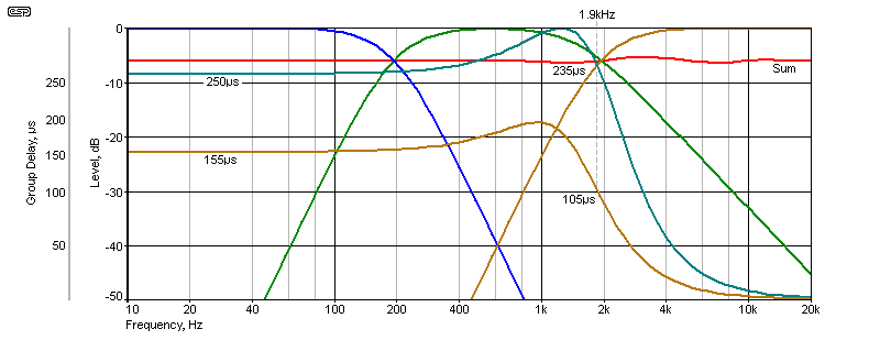
There's only a limited amount of asymmetry that can be applied before the design becomes overly complex, and much experimentation and testing is needed to get a usable result. Any asymmetrical crossover will provide unequal group delay (e.g. 18dB and 12dB/ octave), noting that the greatest delay is provided by the high-order filter. This must be used for the tweeter, with the lower order filter (e.g. 12dB or 18dB/ octave) used for the mid-bass. It should be possible to get the summed response to be flat within ±1dB fairly easily.
Less group delay becomes available if the filters are changed to 3rd order and 2nd order (18dB/ octave and 12dB/ octave). A fairly typical group delay with this arrangement is 70μs, allowing for an AC offset of up to 25mm. You can even use a 24dB high-pass with a 12dB low-pass to get more delay, but it becomes less consistent, and keeping ripple below ±1dB is possible but not at all intuitive. The slow rolloff of the mid-bass driver may cause issues if it has cone breakup effects above the crossover frequency.
This isn't a solution that can be used by anyone who is maths-averse or can't use a simulator at a fairly advanced level. It also requires that you know the acoustic offset, so everything described above is still relevant. Whether you can arrive at a suitable design depends on your skills, measurement accuracy and the drivers you choose. In some cases you can even use this technique with a passive xover design, but this raises even more challenges if the driver impedance is not flat across the xover frequency (and at least 1 octave either side of the xover point, preferably more).
This is a topic that is discussed regularly in forum posts and elsewhere, but there seem to be few decent resources you can draw upon that describe how it can be done. The techniques shown here will give a reasonable approximation to locate the acoustic centre of tweeters and mid-bass drivers. I'd be interested to hear from anyone who has their own favourite technique, and can provide details. Because we are dealing with a moving target, the more information that people can refer to the better.
Of course, the ideal would be for loudspeaker driver manufactures to supply this information along with everything else in their datasheets. Unfortunately, I wouldn't hold my breath waiting. When the drivers are characterised for the datasheet it would be so easy to add this small piece of info to make everyone's life just that little bit easier. Alas, it hasn't happened yet - I have never seen the acoustic centre figure specified in any way, shape or form.
Meanwhile, many modern mid-bass drivers are quite shallow, and some tweeters include a (small) waveguide. A shallow mid-bass and a 'deep' tweeter will minimise the offset, and you can even go to the trouble of fabricating a waveguide for the tweeter that moves it back far enough to achieve time alignment. There is an article on the ESP site covering waveguides, but it's fairly heavy-going (see Practical DIY Waveguides, Part 1 (along with parts 2 & 3) for details.
Waveguides can introduce issues with response, so care (and experimentation) is needed before you commit to this approach. As noted in the article Phase Correction - Myth or Magic, you can use an all-pass filter to provide the required delay for the tweeter, which some people will prefer to a stepped baffle. If you're using a DSP crossover, the ability to add a delay will be in the software, but unless the DSP offers very high performance this may not be an option for hi-if.
None of this is necessary for the woofer to mid-bass/ midrange driver. The crossover frequency will probably be somewhere around 300Hz, at which frequency the wavelength is over one metre, and a timing error of a few 10s of microseconds will have no audible or measurable effect. Some designs may provide correction for the bass-to-mid crossover, but room effects will be so completely dominant that no improvement is likely. Even an AC offset of 200μs (68mm) will have less than 1.5dB effect. Compare that against the measured response of any driver and you'll see that it's insignificant. This is doubly true when in-room response is considered.
Note that I make no claims for the accuracy of any of the techniques described. This article is the result of a number of experiments to locate the acoustic centre of drivers, but all give slightly different results. Other than a specialised test baffle. an anechoic test space and very careful measurements, any method you use will be an estimation. I might (but probably won't) put an adjustable test baffle together at some point, but that would require the anechoic test environment, something I don't have and never will. Frequency response measurements need to be very carefully performed, with the mic at least 1 metre from the drivers.
The most accurate measurement technique is to wire one driver reverse-phase, and adjust for a null (a notch) at the crossover frequency. This is a lot harder than it sounds, because reflections from nearby surfaces (including you!) can easily create false nulls, and/ or obscure the 'real' one. Using close-mic techniques can create serious errors due to the geometrical errors shown in Fig. 2.4. As noted, a directional mic is probably better if you use the null technique, as it will reduce at least some of the reflections. If the measured offset is wildly different from the alignment of the top plates then you've either made an error, or reflections/ standing waves are creating a false null.
 Main Index Main Index  Articles Index Articles Index |