
|
| Elliott Sound Products | AN-019 |
 Main Index
 App. Notes Index
Although I've called this 'zero power', that's not strictly true, since anything that draws current and has some voltage across it must dissipate power. However, where most LED battery indicators draw current that does nothing other than illuminate the LED, this idea puts the LED current to use in the circuit being powered. It only works when you have a regulated supply (e.g. 5V) that's powered by a battery, which will typically be a standard 9V battery for small, low-power applications. It's a clever idea (thanks to B Fraser), and despite a lengthy search I found nothing similar elsewhere.
There is one caveat - the circuit being powered must draw more current than the LED at any battery voltage. Standard voltage regulators can only source current, and if your load only draws a very low current, if the LED current is too high the regulator's output voltage will rise.
Mostly, I'd suggest an 'ultrabright' LED, as these can provide more than enough brightness even with as little as 0.5mA. The basic circuit shown here can be adapted for almost any voltage, but you need to verify the LED forward voltage. It has to be greater than the minimum input-output voltage differential of the regulator. Most common 3-terminal regulators will function down to the point where the input voltage is only about 2V greater than the output.

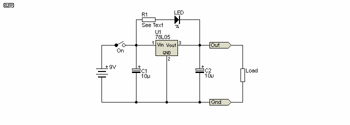
Figure 1 - 'Zero Power' LED Battery Monitor
Provided the battery voltage is greater than ~7V (for a 5V output) the LED will get current via R1. Once the voltage falls below the LED's forward conduction voltage it goes out, indicating that it's time to replace the battery. Because the LED current flows into the load, it's not wasted, and no additional circuitry is required. Your circuit gains just one LED and one resistor. Once the battery voltage falls to ~7V, there's not enough voltage to turn on the LED, so you know that it's time for a new battery.
The resistor (R1) should be selected such that it doesn't pass more current than the circuit following the regulator draws. For example, if your circuit draws 5mA at 5V, the LED current must be less than 5mA with a brand new battery (typically about 10V for a nominal 9V battery). To be safe, I'd recommend a maximum current of about 2.5mA. If the circuit has a low-current 'sleep' function, it may not be possible to use the circuit unless you use an ultrabright LED that will be bright enough with no more than half the current drawn in sleep mode.
If the LED is an ultrabright type and your load draws 10mA (not including the regulator current of about 3mA), aim for LED current of about 2mA with a new battery. That means that R1 will be 1.5kΩ, based on a LED forward voltage of 2.2V. The current with a battery voltage of 7.3V (close to end-of-life) will only be 67µA so the LED will be dim, but still visible. This is not intended to be a precision circuit, simply a useful indicator of battery health. Having the LED current passed to the load means that there's no loss of capacity for the battery, where a parallel LED would draw current that's only used for the LED itself.
| High Intensity | |||
| Colour | Fwd. Volts Min. | Fwd. Volts Max. | Lumuminous Intensity |
| Yellow | 2.0 | 2.6 | 750 |
| Green | 2.4 | 3.0 | 240 |
| Yellow | 2.0 | 2.6 | 750 |
| Red | 1.9 | 2.6 | 1000 |
| Red | 1.8 | 2.2 | 1000 |
| Orange | 2.0 | 2.6 | 1000 |
| Yellow | 2.0 | 2.6 | 1000 |
| Ultrabright | |||
| Colour | Fwd. Volts Min. | Fwd. Volts Max. | Luminous Intensity |
| Red | 2.1 | 2.7 | 7500 |
| Green | 3.9 | 4.5 | 2400 |
| Blue | 3.9 | 4.5 | 750 * |
| Yellow | 2.1 | 2.7 | 5750 |
The above data come from a Vishay LED Lamps datasheet (which fails to specify the units of luminous intensity, but it's probably millicandela [mcd]), and the blue LED indicated with a * looks like a misprint. The 'ultrabright' types are generally the most suitable, but note that blue LEDs have a much higher forward voltage than other colours. In the ultrabright series, the green LED also has a much higher than normal forward voltage. This may (or may not) be the case with equivalent LEDs from a different manufacturer. I didn't include the part numbers as they are supplier specific, and you will have to choose the most appropriate LED from your preferred supplier. As always, you will have to do some research, and you will almost certainly have to test the LED to make sure it turns off before the regulator's input voltage is too low.
Note: The minimum forward voltage is usually specified at a particular operating current, which was not specified in the datasheet used to obtain the figures shown above. A LED with a nominal forward voltage of ~2V may actually still emit some light with as little as 1.6V, so testing is essential. A bench test with a red ultrabright LED showed that at 1.6V (with a 2.7kΩ series resistor) the LED stopped emitting light at almost the exact voltage where the 78L05 dropped out of regulation.
For 'general-purpose' circuitry, the circuit current will generally be no more than 10-20mA if powered from a 9V battery, and a 'high efficiency' LED may suffice. Remember that like all things in electronics, you must be prepared to experiment. If your regulator needs more than around 2V input-output differential, you can add a signal diode (1N4148 or similar) in series with the LED to gain an extra 0.65V of 'headroom'. It is certainly possible to make the LED brightness fairly constant until the 'bitter end', but naturally that makes the circuit a little more complex.

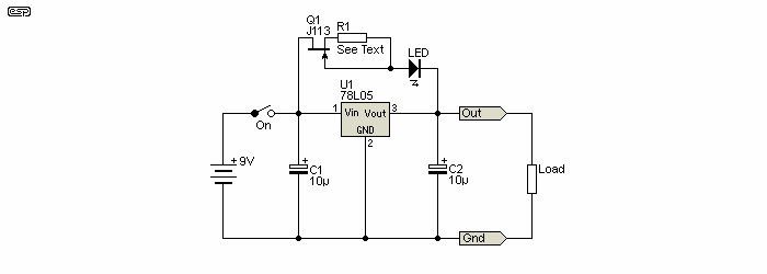
Figure 2 - 'Zero Power' LED Battery Monitor With JFET Current Source
If you really think that the LED's brightness should remain fairly constant until the battery is discharged, you can add a JFET current source. Because JFETs are extremely variable, the resistor value depends on the JFETs characteristics. A good start is around 1kΩ, but it may be higher or lower depending on the JFETs 'pinch-off' voltage (VGS (off)). The FET also adds some extra voltage to that of the LED, and with a 'typical' (if there is such a thing) J113, the LED will go out when the input voltage is about 7.5V, assuming a 2V forward voltage for the LED, and a J113 with a VGS (off) of -1V (the range is from -0.5V to -3V according to the datasheet).
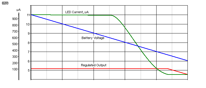
The LED current as simulated is 1mA, more than enough with an ultrabright LED. At 8.4V, the LED current falls to 0.8mA, and by the time the battery is down to 7V, the current is only 100µA. The LED current reduces rapidly below 8V input, so you'll really know that the battery needs to be replaced. I tested the circuit shown in Fig. 2 and LED brightness remains the same with any input voltage greater than 8V (the J113 I used had a VGS (off) of 1.3V). As the voltage fell further, the LED dimmed very noticeably until it extinguished at about 6.8V, just before the 78L05 dropped out of regulation. The LED current was just under 0.5mA, and it is easily visible even under bright lighting.

Figure 3 - LED Current, Battery Voltage And Regulated Output (5V)
The graph shows the LED current vs. battery and output voltages. At about 8.5V, the LED starts to dim as its current is reduced. When the battery voltage reaches 7V, the LED current is only 120µA, and falls to zero just at the point where the regulator drops out. The above was taken from a simulation, but reality is actually slightly better.
It's obvious that additional complexity can give better results, but it also means that you need to select the LED and the JFET and/or the resistor. The JFET should have a VGS (off) of no more than 1V, or the LED dropout voltage will be too high. Whether it's worth the extra fuss depends on your expectations and willingness to experiment. It should be apparent that the LED current still flows to the load, so no current is wasted. The solution with the JFET is more 'elegant' because the LED brightness doesn't change much until the battery is close to being 'flat'.
Figure 1 idea submitted by B Fraser (first initial used by request).
Datasheet ...
 Main Index
 App. Notes Index