
|
| Elliott Sound Products | AN-015 |
 Main Index
 App. Notes Index
Every circuit made doesn't necessarily need input protection, but where it's included it makes sense that it should actually work. It's very common to see input protection schemes that use diodes from the input to the power supply rails. While this can work well, there are circumstances where it not only doesn't provide protection for the input stage, but it can destroy the rest of the circuit as well. Admittedly, such occurrences are rare and somewhat unusual, but that does not mean they can't (or won't) happen. I know for a fact that they can (and do) happen!
Look in almost any datasheet that provides 'application examples', and whenever input 'protection' is shown (which isn't as common as you might hope), it will almost invariably use low current diodes from the input(s) to the supply rails. A limiting resistor may or may not be included, with the latter case more likely. This is fake protection - it will only provide the most basic protection for obviously foreseeable connection errors, but will do nothing to protect an input circuit that's accidentally been connected to a speaker output. This does happen, and probably far more often than most people might think. Perhaps surprisingly, using bigger diodes (e.g. 1N4004 or similar) only makes matters worse.
Consider the input to a PC oscilloscope adapter, as shown in Project 154. Because of the way I designed it, it's pretty safe even if the input is connected to a high voltage AC or DC supply, because there's capacitor to block DC and a 100k input resistor that limits the current. Even if 400V were to be applied to the input, there will be a brief voltage pulse as the input cap charges, but the peak current is limited to 4mA. Even a high AC voltage won't hurt it, because the battery is a low impedance and can absorb a small 'charge' current (although it will not actually recharge).
This doesn't stress anything for very long, and it will survive. However, there are countless circuits in magazines and on the Net where no such limiting resistor is included, and in many cases the circuit may be such that it could easily be connected to a high voltage supply, either by accident, due to a component failure or because the user doesn't understand that (for example) 5V circuitry such as microcontrollers or analogue to digital converters really don't like high voltages, and will show their displeasure by failing - usually catastrophically.
There is a strong likelihood that other low voltage circuitry will be damaged as well, and it could spell the end of a project, requiring a complete re-build. This is certainly not something that happens regularly, but it's unreasonable to expect that it will not happen on occasion. The user is left wondering how so many parts were fried, even though there are protection diodes in place. In some cases you may even be unaware that the worst-case 'protection' system is in place, because it's sometimes included in ICs (the datasheet will usually indicate that it's present). This is generally included for ESD (electrostatic discharge) protection, and being integrated, the diodes are small and very limited current. I have heard of a complete multi-channel mixer that had most of its opamps destroyed because someone mistook the speaker output jack for the line output jack on a guitar amplifier.
A protection topology has to be chosen to suit the specific needs of your circuit. If you only need to protect against ESD (electrostatic discharge) the voltage may be high (several thousand volts is not uncommon), but the available current is low because ESD 'events' are limited by the circuit capacitance which usually includes a person. Standard ESD tests assume a 'human body model' having a capacitance of around 100pF in series with 1,500 ohms [ 1 ]. The test voltages range from 2kV to 8kV, so worst case input current ranges from 1.33A (2kV) up to 5.33A (8kV). While 1N4148 diodes can handle the lower current easily, they may not survive with 5.3A, even if it's very brief. At a test voltage of 2kV, the current is greater than 500mA for around 150µs. With 8kV, that's extended to 350µs.
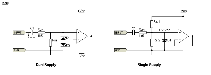
The input resistor RLIM is expected, but isn't always used. It's also a compromise, because the resistance has to be low enough so as to not generate excessive noise, yet needs to be large enough to ensure the current is limited to a safe value. With 1.5k as shown, peak current is half the theoretical 'worst case' value for an ESD test. The value of the input capacitor (C1) has not been specified, because it's dependent on the circuit's usage. Low values may offer better protection because the peak current pulse may be shorter (for very low values at least), but for low impedance, low frequency circuits it needs to be fairly large.
In the following circuits, an opamp is shown as the 'input device' that requires protection. In reality, it could just as easily be a small signal MOSFET, an ADC (analogue to digital converter) or any other IC or active device. Examples are shown for dual supply and single supply operation. Single supply input ICs are a little easier to protect than those using a dual supply. The examples also include an (optional) input capacitor, which may or may not be essential, depending on the purpose of a circuit. Where single supply inputs are used, the input cap is almost always needed so the source doesn't short circuit the input biasing.
While component destruction may be common due to ESD transients or other events, it's not always immediately apparent. During testing of a discrete transistor, I found that a single impulse left the transistor in a working condition, but its performance had deteriorated. The gain was lower, and although not tested at the time, I'd also expect noise to be increased. Further 'events' caused the gain to drop again, and it took several test cycles before the degradation would have been immediately apparent.
In the meantime (after perhaps two or three test cycles), in a complete circuit I would expect to see a small reduction in AC voltage gain, but likely a disproportionately large distortion (and noise) increase because open loop gain is reduced and feedback is not as effective. The average user (and quite possibly any user) could be unaware of this, but left wondering why the sound quality just doesn't seem 'right'. This insidious degradation could continue over a period of time before being positively identified as a fault. ICs usually save you the trouble - a single transient event will kill a FET input opamp first try (I know this because I did it several times while running tests).
It's important to understand that virtually no input protection scheme will provide any useful safeguard against the input being connected to the mains AC supply. The mains is at a very low impedance and can provide more than enough current to blow up almost anything that's not rated for mains input. Although it's very unlikely that anyone would be silly enough to expect an electronic device to survive a direct connection to the mains supply, it's worth mentioning 'just in case'. Devices intended to measure/ monitor mains voltages must be designed accordingly, otherwise they simply go bang !
One of the reasons that the 'traditional' protection circuit is flawed is that power supply regulator ICs are designed to do one thing - provide output current at the specified voltage. They cannot sink (absorb) current that's provided at their output terminal by a fault, and without any restraint the output voltage can easily be forced to a dangerously high level.
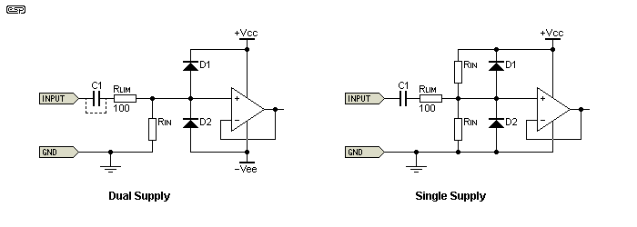
The 'traditional' schemes are shown below, but unlike many you'll see, they include RLIM which helps a little. Should a high input voltage (of either polarity) be connected to the input, the appropriate diode conducts and the input is protected. Well, not always. What happens if the circuit shown is inadvertently connected to a +35V DC supply (a power amp's supply rail perhaps). The diode will conduct, but it will force current back into the supply rail. This is not a problem if the input capacitor is present, but DC coupled circuits that do not use a capacitor are at some risk. AC voltages above the supply rails can still cause havoc even if the capacitor is present, provided its value is high enough. 10µF or more could easily cause problems, and if the input is from a power amp, the frequency may be high enough to make the capacitor irrelevant. A 10µF cap has a reactance of only 16 ohms at 1kHz.
A circuit that runs from ±15V will not be happy if one rail (or both with AC) is suddenly raised to more than 30V, and further down the line, there's a voltage regulator that now has over 30V on its output pin. Unless there is a diode across the regulator (as shown in all ESP regulator designs), the regulator IC will be reverse biased and will probably fail. Even if the diode is present, the maximum operating voltage of the IC may be exceeded if the fault condition is sustained, leading to destruction.

Figure 1 - Traditional Over-Voltage Protection
The standard arrangement provides a false sense of security, and can lead to catastrophic failures. In a great many cases, the vulnerability of the circuit will never be tested, so a product can have a built-in failure mechanism that only a few people will ever find. Many products will have a 'user manual' that points out that "incorrect usage voids any warranty". The unfortunate user who failed to realise that some high voltage was present is left with a dead unit, with no hope of restitution.
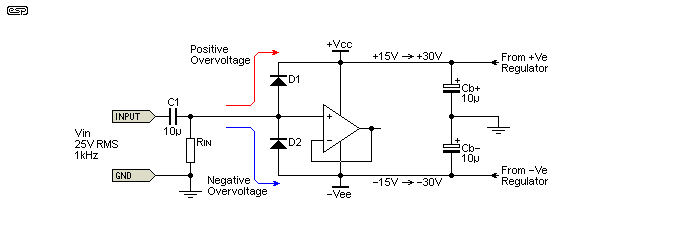
For single supply applications (which are typically powered from a 5V supply), the diode to ground will usually provide reasonable protection provided the current is limited, but no such protection is offered if a DC coupled input is connected to a DC voltage of more than 5V. Even 12V from an opamp supply may be enough to cause damage if current limiting is not provided. Remember that the input capacitor will prevent long term over-voltage from causing havoc, but only if its voltage rating is high enough to withstand the applied voltage. Naturally, this doesn't apply if the input is AC, whether from the secondary of a transformer, the output from a power amplifier, or some other source of AC at any frequency. Consider the following (with RLIM not installed ...

Figure 2 - Over-Voltage Protection (Epic) Fail
With the input voltage shown (roughly ±35V peak) and a more-or-less standard input 'protection' circuit, it takes less than 3 cycles (3ms) to 'pump' the supply rails up to over ±30V, even with a total nominal load of 15mA on each supply (rising to 30mA). Will the opamp survive this? What about the regulator, which has an output voltage perhaps 10V greater than the input voltage from the rectifiers? Some may survive (especially if the regulators have reverse diodes which passes the voltage rise to the input, as seen in all ESP designs), but many will not. Larger bypass caps (Cb+ and Cb-) slow the process down, but do not fix the problem.
If an input limiting resistor is included the circuit will work properly, but only if the value is high enough. Even 100 ohms provides minimal real protection, and it needs to be at least 1k, and preferably 1.5k as shown in the other examples.
It has to be admitted that the likelihood of this happening is small, but it's still real. Commercially produced equipment is used by 'ordinary' people (i.e. those with no electronics knowledge), who will be unaware that you must never connect low-level circuitry to the outputs of an amplifier (whether by accident or otherwise). Even dedicated hobbyists may do it accidentally, but they will be able to repair the damage. The average consumer is left with a piece of junk that no longer works, there's no warranty and not many people around any more who can fix it.
A better method is shown next. The power ratings for the zeners is determined by the level of protection required and the series input resistance RLIM. In many cases, the latter will be fairly low (around 100 ohms or so, rather than 1.5k as shown), and the zener diodes will clamp the input voltage even if operating at several times their continuous current rating. This cannot be maintained for long of course, because the conducting zener will overheat and fail, probably along with the input resistor. This is a cheap and easy repair, something a 'handyman' (or woman) can likely do themselves.

Figure 3 - Alternative Over-Voltage Protection
More importantly, the remainder of the circuit is safe. The input resistor will (hopefully) fail first, but even if a zener fails, like all semiconductors it will fail short circuit. Now, only an input resistor and a pair of zener diodes need to be replaced, and not the entire circuit and power supply. Naturally, this scheme is not completely foolproof (apparently fools are too ingenious), but it's a lot better than the traditional scheme. The zener voltage needs to be selected carefully to ensure that the input signal isn't distorted. For the single supply version, the zener would probably be 5.1V to suit a 5V supply.
There are several things you need to be aware of though, and these can be a real problem for high impedance circuits that are expected to operate at high frequencies. The biggest issue is the capacitance of the zener diodes. Where a 1N4148 diode has a capacitance of around 4pF, the junction capacitance of zeners is often not specified. It is a great deal higher than that for small-signal diodes (e.g. 1N4148), and it also depends on the zener voltage. Low voltage zeners have higher capacitance than high voltage versions of the same family.
For example, a 5.1V zener may have a junction capacitance of over 100pF, while a 20V version could be as low as 20pF [ 2 ]. This is often specified at a particular reverse voltage (2V for example), but the capacitance is voltage dependent and increases as the reverse voltage is reduced. So, while zeners are fine for low impedance circuits, they may cause premature high frequency rolloff once the impedance gets much over 22k or so. The arrangement shown was used in the Project 96 phantom power adaptor for microphones, because it's the only way to be certain that damaging transients cannot be delivered to the microphone preamp's inputs.
All is not lost though. It's possible to have a high impedance input that is well protected against most possible over-voltage conditions. There are limits of course, because small-signal diodes with low capacitance are also limited to relatively low current. Even a 1N4148 (or the low capacitance version, the 1N4448) can withstand 1A for one second, or 4A for 1µs. The voltage across it will be a great deal higher than the nominal 650mV normally expected though, and this has to be considered. It's obvious that the supply rails must be maintained at a safe voltage for the IC, and for its inputs. While many ICs have at least some degree of input protection built in, many don't. The specifications will state that (for example) the inputs must be maintained within the range from -Vee - 0.3V to +Vcc + 0.3V or the circuit may malfunction.

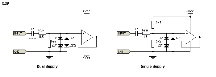
Figure 4 - Combination Over-Voltage Protection
The arrangement shown above can achieve everything needed, but it now requires four diodes. However, if you really need to protect the inputs from potentially dangerous voltages, then it's a small price to pay to achieve reliability. The advantage is that low capacitance diodes can be used in series with the zeners, so their relatively high capacitance is isolated from the input circuitry. This improves high frequency response in high impedance circuits. The current limiting resistor is still very important, and needs to be selected to suit the expected worst case input voltage.
The zener diodes (ZD1 and ZD2) would typically be selected for around 2-3V less than the supply rail voltages. For ±15V, 12V zeners are pretty much ideal. Zener diodes usually have a fairly high capacitance, and this is important for high impedance applications, as it will cause premature high frequency rolloff. Expect up to 40pF for 10V zeners, which is reduced to ~20pF when two are in series (back-to-back).
You may think that using Schottky diodes would be good idea, but their capacitance is typically quite a bit higher than 'ordinary' small-signal diodes, and they have much higher leakage which may cause distortion. You can expect around 7pF junction capacitance for BAT43 diodes (30V, 200mA continuous). It may not sound like a great deal, but with a 100k source impedance, a pair of BAT43 diodes will cause the -3dB frequency to be only 114kHz, assuming there is zero stray capacitance to reduce it further. This is not an issue for audio, but for a test instrument it may be very limiting.
Input protect seems like the simplest thing in the world - until you examine all the possibilities of things that may go wrong. Circuits with an input coupling capacitor fare a little better, because a high voltage applied to the input will generate a high current, but only for a short time (assuming that the capacitor is rated for the expected worst case input voltage of course). An under specified cap may fail or suffer such high leakage that damage is caused anyway. Including a protection circuit that doesn't actually protect against foreseeable accidents isn't helpful - especially if it's capable of causing further damage within the equipment.
In most cases, it will be alright to use 'traditional' scheme shown in Figure 1, but you must add zeners directly across each supply rail. Obviously they must have a breakdown voltage that's greater than the supply voltage. If you have ±15V supplies, you need to use 16V zeners, which will have a typical voltage range from 15.3V to 17.1V. Zener diodes are not precision components, and 5% tolerance is probably the best you can hope for.
Input protection is now an essential part of any project that connects to external sources that may be powered by a switchmode power supply. This is described in detail in the article on low voltage external switchmode power supplies (External PSUs). These commonly have a 'floating' 50/60Hz voltage present at the output, that is around 50% of the mains voltage. The available current is small, but more than sufficient to damage even a discrete transistor's base-emitter junction. Integrated circuits are even more vulnerable because the transistors are physically much smaller and are more easily damaged. In case you were wondering, this is something I have physically tested, so it's a fact, not a hypothesis.
Ultimately, the level of protection provided depends on the application. Not everything needs a very high level of protection, and in some cases including it may degrade the circuit's performance. This will most commonly be in situations where the added capacitance of the diodes cause a high frequency rolloff with high source impedances, but diode leakage can also be an issue in some cases. If the lowest noise is desired, adding series resistance is not the answer, because the resistor contributes noise of its own. I usually don't include input protection circuits because hi-fi preamps, electronics crossovers and many of the other projects will be permanently wired, usually in such a way as to make it extremely unlikely that protection will ever be required.
However, if you do decide to include protection, it's important that it will actually work. A 'protection' scheme that can destroy the entire circuit is neither useful nor helpful. You will be lulled into a false sense of security, which doesn't help anyone. Before you embark on any protection scheme, make sure that you test it thoroughly in the way it will normally be used, and be prepared to make changes to ensure that it does its job even if the owner does something really stupid (most won't, but rest assured that someone will! If the protection degrades the performance or causes some other undesirable anomaly, be willing to make other changes.
For example, if the first opamp must have a high input impedance and minimal capacitance, isolate its power supply with diodes, use a resistor from the output to limit current into following circuitry (with zener diodes to ground), and install it in a socket. Yes, the opamp will blow up if someone does something particularly nasty to it, but with careful design the remainder of the circuit will survive.
In general, it's a particularly (and spectacularly!) bad idea to use the same type of connector for inputs and outputs. For example, a certain British manufacturer of guitar amplifiers also makes (or made) rack mounted amplifiers, and used 6.35mm (1/4") jack sockets for both inputs and outputs, all in a neat row together. The opportunity for a mix-up is glaringly obvious, and no input protection is provided at all! There's also a litany of other design flaws in some, but that's outside the scope of this article.
 Main Index
 App. Notes Index