
|
|
| Elliott Sound Products | Amplifier Sound - What Are The Influences? |
 Main Index
Articles Index
Main Index
Articles Index
Contents
The sound of an amplifier is one of those ethereal things that seems to defy description. I will attempt to cover the influences I know about, and describe the effects as best I can. This is largely hypothesis on my part, since there are so many influences that, although present and audible, are almost impossible to quantify. Especially in combination, some of the effects will make one amp sound better, and another worse - I doubt that I will be able to even think of all the possibilities, but this article might help some of you a little - at least to decipher some of the possibilities.
I don't claim to have all the answers, and it is quite conceivable that I don't have any (although I do hope this is not the case). This entire topic is subject to considerable interpretation, and I will try very hard to be completely objective.
Reader input is encouraged, as I doubt that I will manage to get everything right first time, and there are some areas where I do not really know what the answers are. The only joy I can get from this is that I doubt that anyone else can do much better. If you can, let me know.
Unfortunately, it can be extremely difficult for the novice to figure out what on-line information is reliable, what is unmitigated drivel, and which material has a random mixture of both. There are some extraordinarily dubious claims made, and as an example I offer the following gem (reproduced verbatim) ...
"A modern high-quality audio system has excellent specifications and sounds almost perfect. Almost perfect, but not quite. There is one very important attribute missing in audio systems - the attribute we call 'presence'. This article discusses an alternative power amplifier design with sound that often lacks in conventional amplifiers. Even the best commercially available audio systems lack real presence - while the sound can be crystal clear, you would never mistake the recorded voices for real voices, or the recorded piano for a real piano. The human ear immediately knows the difference.
As listeners, even as audiophile listeners, we don't fuss about this lack of presence because we have come to accept that what we hear from a modern audio system is as good as it gets. Yet this just isn't true, and it doesn't have to be accepted.
The lack of presence occurs almost entirely as a result of distortions inherent in the fundamental design of all commercial power amplifiers. Have you noticed how much clearer headphones sound? It's due to the fact that they are driven by low-powered amplifiers."
This nonsense has just enough (semi) truth to appear plausible, but as it continues the claims become less coherent. A recorded sound is different from a live sound because there's a microphone and speakers between the source and your ears. It has nothing to do with the amplifier, and especially nothing to do with the amplifier's power. Headphones sound clearer (except when they don't) because of the headphone drivers and intimate coupling with our hearing mechanism. The amplifier power is utterly irrelevant, and the third paragraph is unmitigated drivel!
I could dissect the claims (which continue ad nauseam in the full text) in greater detail, but frankly it's not worth the electrons that would be used to transport the text. The article goes on to extol the 'virtues' of a rather odd amplifier topology that saw daylight for perhaps 30 seconds or so back in 1971, and never saw commercial production. It was published in Wireless World, but doesn't appear to have ever been re-published elsewhere. The amp used a single supply, so was capacitor coupled to the speaker, and while the basic design works well enough (or so it's claimed), almost no-one wants capacitively coupled speakers any more.
When people talk about the sound of an amplifier, there are many different terms used. For a typical (high quality) amplifier, the sound may be described as 'smeared', having 'air' or 'authoritative' bass. These terms - although describing a listener's experience - have no direct meaning in electrical terms. The term 'presence' referred to above is created in guitar amps (for example) by boosting the frequencies around 3kHz - it's not something found in power amplifiers.
Electrically, we can discuss distortion, phase shift, current capability, slew rate and a myriad of other known phenomena. I don't have any real idea as to how we can directly link these to the common terms used by reviewers and listeners.
Some writers have claimed that all amplifiers actually sound the same, and to some extent (comparing apples with apples) this is 'proven' in double-blind listening tests. I am a great believer in this technique, but there are some differences that cannot be readily explained. An amp that is deemed 'identical' to another in a test situation, may sound completely different in a normal listening environment. It is these differences that are the hardest to deal with, since we do not always measure some of the things that can have a big influence on the sound.
For example; It is rare that testing is done on an amplifier's clipping performance - how the amp recovers from a brief transient overload. I have stated elsewhere that a hi-fi amplifier should never clip in normal usage - nice try, but it IS going to happen, and often is more common than we might think. Use a good clipping indicator on the amp, and this can be eliminated, but at what cost? It might be necessary to reduce the volume (and SPL) to a level that is much lower than you are used to, to eliminate a problem that you were unaware existed.
Different amplifiers react in different ways to these momentary overloads, where their overall performance is otherwise almost identical. I have tested IC power amps, and was dismayed by the overload recovery waveform. My faithful old 60W design measures about the same as the IC in some areas, a little better in some, a little worse in others (as one would expect).
Were these two amps compared in a double blind test (avoiding clipping), it is probable that no-one would be able to tell the difference. Advance the level so that transients started clipping, and a fence post would be able to hear the difference between them. What terms would describe the sound? I have no idea. The sound might be 'smeared' due to the loss of detail during the recovery time of the IC amp. Imaging might suffer as well, since much of the signal that provides directional cues would be lost for periods of time.
A detailed description of the more important (from a sound perspective) of the various amplifier parameters is given later in this article, but a brief description is warranted first. Items marked with a * are problem areas, and the effect should be minimised wherever possible. The parameters that should normally be measured (although for those marked # this is rare indeed) are as follows:
¹ Important parameter
² Rarely measured
Every amplifier design on the planet has the same set of constraints, and will exhibit all of the above problems to some degree. The only exception is a Class-A amplifier, which does not have crossover distortion, but is still limited by all other parameters.
The difficulty is determining just how much of any of the problem items is tolerable, and under what conditions. For example, there are many single ended triode valve designs which have very high distortion figures (comparatively speaking), high output impedance and low output current capability. There are many audio enthusiasts who claim that these sound superior to all other amplifiers, so does this mean that the parameters where they perform badly (or at least not as well as other amps) can be considered unimportant? Not at all!
If a conventional (i.e. not Class-A) solid state amplifier gave similar figures, it would be considered terrible, and would undoubtedly sound dreadful.
3.0 Distortion
Technically, distortion is any change that takes place to a signal as it travels from source to destination. If some of the signal 'goes missing', this is distortion just as much as when additional harmonics are generated.
We tend to classify distortion in different ways - the imperfect frequency response of an amplifier is not generally referred to as distortion, but it is. Instead, we talk about frequency response, phase shift, and various other parameters, but in reality they are all a form of distortion.
The bottom line is that amplifiers all suffer from some degree of distortion, but if two amplifiers were to be compared that had no distortion at all, they must (by definition) be identical in both measured and perceived sound.
Naturally, there is no such thing as a perfect amplifier, but there are quite a few that come perilously close, at least within the audible frequency range. What I shall attempt to do is look at the differences that do exist, and try to determine what effect these differences have on the perceived 'sonic quality' of different amplifiers. I will not be the first to try to unravel this mystery, and I doubt that I will be the last. I also doubt that I will succeed, in the sense that success in this particular area would only be achieved if everyone agreed that I was right - and of that there is not a chance! (However, one lives in hope.)
In this article I use the somewhat outdated term 'solid state' to differentiate between valve amps, and those built using bipolar transistors, MOSFETs or other non-vacuum tube devices.
I have also introduced a new (?) test method, which I have called a SIM (Sound Impairment Monitor), the general concept of which is described in the appendix to this article.
How can one amplifier's clipping distortion sound different from that of another? Most of the hi-fi fraternity will tend to think that clipping is undesirable in any form at any time. While this is undeniably true, many of the amps used in a typical high end setup will be found to be clipping during normal programme sessions. I'm not referring to gross overload - this is quite unmistakable and invariably sounds awful - regardless of the amplifier.
There are subtle differences between the way amplifiers clip, that can make a great impact on the sound. Valve amps are the most respectable of all, having a 'soft' clipping characteristic which is comparatively unobtrusive. However, this comes at a cost. While distortion can be very low at low levels, with low feedback valve amp designs, the distortion rises as level increases. The change from 'unclipped' to 'clipped' may be less abrupt, but the distortion just before clipping can be surprisingly high. Low feedback Class-A amplifiers are next, with slightly more 'edge', but otherwise are usually free from any really nasty additions to the overall sound.
Then there are the myriad of Class-AB discrete amps. Most of these (but by no means all) are reasonably well behaved, and while the clipping is 'hard' it does not have significant overhang - this is to say that once the output signal is lower than the supply voltage again it just carries on as normal. This is the ideal case - when any amp clips, it should add no more nastiness to the sound than is absolutely necessary. Clipping refers to the fact that when the instantaneous value of output signal attempts to exceed the amplifier's power supply voltage, it simply stops, because it cannot be greater than the supply. We know it must stop, but what is of interest is how it stops, and what the amplifier does in the brief period during and immediately after the clipping has occurred.
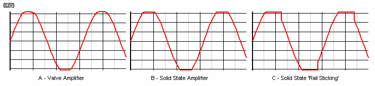
Figure 1 - Comparison of Basic Clipping Waveforms
In Figure 1, you can see the different clipping waveforms I am referring to, with 'A' being representative of typical push-pull valve amps, 'B' is the waveform from a conventional discrete Class-AB solid state amp, and 'C' shows the overhang that is typical of some IC power amps as well as quite a few discrete designs. This is a most insidious behaviour for an amp, because while the supply is 'stuck' to the power rail, any signal that might have been present in the programme material is lost, and a 100Hz (or 120Hz) component is added if the clipping + 'stuck to rail' period lasts long enough. This comes from the power supply, and is only avoidable by using a regulated supply or batteries. Neither of these is cheap to implement, and they are rarely found in amplifier designs.
Although Figure 1 shows the signal as a sinewave for ease of identification, in a real music signal it will be a sharp transient that will clip, and if the amp behaves itself, this will be (or should be) more or less inaudible. Should it stick to the supply rail, the resulting description of the effect is unlikely to accurately describe the actual problem, but describe what it has done to the sound - from that listener's perspective. A simple clipped transient should not be audible in isolation, but will have an overall effect on the sound quality. Again, the description of this is unlikely to indicate that the amp was clipping, and regrettably few amps have clipping indicators so most of the time we simply don't know it is happening.
To be able to visualise the real effect of clipping, we need to see a section of 'real' signal waveform, with the lowest and highest signal frequencies present at the same time. If the amp is clipped because of a bass transient (this is the most common), the period of the waveform is long. even if the signal is clipped for only 5 milliseconds, this means that 5 complete cycles of any signal at 1000Hz are removed completely, or 50 complete cycles at 10kHz. This represents a significant loss of intended information, which is replaced by a series of harmonics of the clipped frequency (if clipping lasts for long enough), or more typically a series of harmonics that is not especially related to anything (musically speaking - all harmonics are related to something, but this is not necessarily musical!)
I think that no review of any amplifier should ever be performed without some method of indicating that the amp is clipping (or is subject to some other form of signal impairment), and this can be added to the reviewer's notes - along the lines of ...
"This amplifier was flawless when kept below clipping (or as long as the SIM (or other signal integrity monitoring facility) failed to show any noticeable impairment), but even the smallest amount of overload caused the amp to sound very hard. Transparency was completely lost, imaging was ruined, and it created listener fatigue very quickly."
Now, wouldn't that be cool? Instead of us being unaware (as was the reviewer in many cases) that the amp in review was being overdriven - however slightly - we now (all of us) have that missing piece of information that is not included at the moment. I have never seen a review of an amp where the output was monitored with an accurate clipping indicator to ensure that the reviewer was not listening to a signal that was undistorted. I'm not saying that no-one does this, just none that I have read.
The next type of overload behaviour is dramatically worse, and I have seen this in various amps over the years. Most commonly associated with overload protection circuits, the sound is gross. I do not know the exact mechanism that allows this to happen, but it can be surmised that the protection system has 'hysteresis', a term that is more commonly associated with thermal controllers, steel transformer laminations and Schmitt trigger devices. Basically, a circuit with hysteresis will operate once a certain trigger point is reached, but will not reset until the input signal has fallen below a threshold that is lower than the trigger point. The typical waveform of an amplifier with this problem is shown in Figure 2, and I believe it IS a problem, and should be checked for as a normal part of the test process. This type of overload characteristic is not desirable in any way, shape or form.
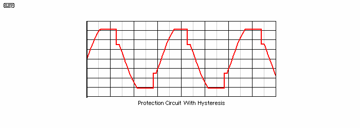
Figure 2 - Hysteresis Overload Waveform
In this case, the additional harmonic components added to the original sound will be more prominent than with 'normal' clipping. As before, I cannot even begin to imagine how the sound might be described - all the more reason to ensure that testing includes informing the reader if the amp was clipping or not during the listening tests. The loss of signal with this type of distortion will generally be much greater than simple clipping, and the added harmonic content will be much more pronounced, especially in the upper frequencies.
Clipping Synopsis
Tests conducted as a part of any review would be far more revealing if the clipping waveform were shown as a matter of course. After some learning on our behalf, we would get to know what various of the hi-fi press meant when they described the sound while the amp was clipping, versus not clipping, or what the amp sounded like when its overload protection circuits came into action.
To this end I have designed a new distortion indicator circuit, which not only indicates clipping, but will show when the amp is producing distortion of any kind beyond an acceptable level. One version has been published as a project, and I have chosen the acronym SIM (Signal/ Sound Impairment Monitor) for this circuit.
The SIM will react to any form of signal modification, and this includes phase distortion and frequency response distortion. I do not believe that this approach has been used before in this way. It is not an uncommon method for distortion measurement, but has not been seen anywhere as a visual indicator for identifying problem areas that an amp may show in use. This circuit will also show when an amplifier's protection circuit has come into effect.
Although the detector has no idea what type of problem is indicated, it does indicate when the input and output signals no longer match each other - for whatever reason. Oscilloscope analysis would be very useful using this circuit, as with a little practice we would be able to identify many of the currently unknown effects of various amplifier aberrations. Any amp behaviour that results in the input and output signals being unequal (within a few millivolts at most) indicates that something is wrong.
Class-A amplifiers have no crossover distortion at all, because they maintain conduction in the output device(s) for the entire waveform cycle and never turn off. Class-A is specifically excluded from this section for that reason.
For the rest, a similar question as the one before - how can one amplifier's crossover distortion sound different from another? Surely if there is crossover distortion it will sound much the same? Not so at all. Again, valve amplifiers are much better in this area than solid state amps (at least in open loop conditions). When valves cross over from one output device to the next (standard push-pull circuit is assumed), the harmonic structure is comprised of mainly low order odd harmonics. There will be some 3rd harmonics, a smaller amount of 5th, and so on.
Solid state amps tend to create high order odd harmonics, so there will be the 3rd harmonic, only a tiny bit less of the 5th harmonic, and the harmonics will extend across the full audio bandwidth. Transistor and MOSFET amps have very high open loop gains, and use feedback to reduce distortion. In all cases, the crossover distortion is caused because the power output devices are non-linear. At the low currents at which the changeover occurs, these non-linearities are worse, as well, the devices usually have a lower gain at these currents.
This has two effects. The open loop gain of the amplifier is reduced because of the lower output device gain, so there is less negative feedback where it is most needed. Secondly, the feedback tries to compensate for the lower gain (and tries to eliminate the crossover distortion), but is limited by the overall speed of the internal circuitry of the amplifier. This results in sharp transitions in the crossover region, and any sharp transition means high order harmonics are produced (however small they might be).
One method to minimise this is to increase the quiescent (no signal) current in the output transistors. With a linear output stage in a well designed circuit, crossover distortion should be all but non-existent with any current above about 50 to 100mA (but note that if the quiescent current is increased too far, overall distortion may actually get worse). Figure 3 shows the crossover distortion (at the centre of the red trace) and the residue as seen on an oscilloscope (green trace, amplified by 10 for clarity) - this is the typical output from a distortion meter, with an amplifier that has noticeable crossover distortion. If measured properly, the distortion is highly visible, even though it may be barely audible. Note that the waveform below would not qualify for the last statement - this amount of crossover distortion would be very audible indeed.

Figure 3 - Crossover Distortion Waveform
If THD is quoted without reference to its harmonic content, then it is quite possible that two amplifiers may indicate identical distortion figures, but one will sound much worse than the other. Distortion at a level of 1W should always be quoted, and the waveform shown. Once the waveform can be seen, it is easy to determine whether it will sound acceptable or dreadful - before we even listen to the amp. Listening tests will confirm the measured results with great accuracy, although the descriptive terms used will vary, and may not indicate the real problem.
Crossover Distortion Synopsis
Although this is one area where modern amplifiers rarely perform badly, it is still important, and should be measured and described with more care than is usually the case. While few amplifiers will show up badly in this test now, crossover distortion was one of the main culprits that gave solid state a bad name when transistors were first used in amplifiers.
I do not believe that we can simply ignore crossover distortion on the basis that "everyone knows how to fix it, and it is not a problem any more". I would suggest that it is still a real problem, only the magnitude has been reduced - the problem is still alive and well. Will you be able to hear it with most good quality amp? Almost certainly not.
Distortion of the frequency response should not be an issue with modern amplifiers, but with some (such as single ended triode valve designs), it does pose some problems. The effect is that not all frequencies are amplified equally, and the first to go are the extremes at both ends of the spectrum. It is uncommon for solid state amps to have a frequency response at low powers that extends to anything less than the full bandwidth from 20Hz to 20kHz. This is not the case with some of the simple designs, and single ended triode (SET) Class-A - as well as inductance loaded solid state Class-A amps - will often have a less than ideal response.
I would expect any amplifier today should be no more than 0.5dB down at 20Hz and 20kHz, referred to the mid-band frequency (usually taken as 1kHz, but is actually about 905Hz). (My preferred test frequency is 440Hz (concert pitch A, below middle C), but none of this is of great consequence.) 0.5dB loss is acceptable in that it is basically inaudible, but most amps will do much better than this, with virtually no droop in the response from 10Hz to over 50kHz.
For reference, the octaves included for 'normal' sound are:
20 40 80 160 320 640 1,280 2,560 5,120 10,240 20,480 (all in Hertz)
To determine the halfway point between two frequencies one octave apart, we multiply the lower frequency by the square root of 2 (1.414). The halfway point is between 650 and 1280Hz, or 904.96Hz. You must be so pleased to have been provided with this piece of completely useless information! Just think yourselves lucky that I didn't tell you how to calculate the distance between the frets on a guitar. 
Most amplifiers will manage well beyond the range necessary for accurate reproduction, at all power levels required to cater for the requirements of music. So why are some amps described as having poor rendition of the high frequencies? They may be described as 'veiled' or something similar, but there is no measurement that can be applied to reveal this when an amplifier is tested. Interestingly, some of the simpler amplifiers (again, such as the single ended triode amps) have poorer response than most of the solid state designs, yet will regularly be described as having highs that 'sparkle', and are 'transparent'.
These terms are not immediately translatable, since they are subjective, and there is no known measurement that reveals this quality. We must try to determine what measurable effect might cause such a phenomenon. There are few real clues, since amplifiers that should not be classified as exceptional in this area are often described as such. Other amps may be similarly described, and these will not have the distortion of a single ended triode and will have a far better response.
We can (almost) rule out distortion as a factor in this equation, since amps with comparatively high distortion can be comparable to others with negligible distortion. Phase shift is also out of the question, since amps with a lot of phase shift can be favourably compared to others with virtually none. One major difference is that typical SET amplifiers have quite high levels of low order even harmonics. Although these will give the sound a unique character, I doubt that this is the sole reason for the perceived high frequency performance - I could also be wrong.
Phase distortion occurs in many amplifiers, and is worst in designs using an output transformer or inductor (sometimes called a choke). The effect is that some frequencies are effectively delayed by a small amount. This delay is usually less than that caused by moving one's head closer to the loudspeakers by a few millimetres. It is generally thought to be inaudible, and tests that I (and many others) have conducted seem to bear this out.
Frequency And Phase Distortion - Synopsis
There must be some mechanism that causes multiple reviewers to describe an amplifier as having a poor high frequency performance, such as (for example) a lack of transparency. There are few real clues that allow us to determine exactly what is happening to cause these reviewers to describe the sound of the amp in such terms, and one may be tempted to put it all down to imagination or 'experimenter expectancy'. This is likely to be a mistake, and regardless of what we might think about reviewers as a species, they do get to listen to many more amplifiers than most of us.
One of the few variables is a phenomenon called slew rate. This is discussed fully in the next section.
This has always been somewhat controversial, but no-one has ever been able to confirm satisfactorily that slew rate (within certain sensible limits) has any real effect on the sound. Figure 4 is a nomograph that shows the required slew rate for any given power output to allow full power at any frequency. To use it, determine the power and calculate the peak voltage, and place the edge of a ruler at that voltage level. Tilt the ruler until the edge also aligns with the maximum full power frequency on the top scale. The slew rate is indicated on the bottom scale.
For example, if the peak voltage is 50V (a 150W/8 ohm amp) and you expect full power to 20kHz, the required slew rate is 6V/µs. Bear in mind that no amplifier is ever expected to provide full power at 20kHz, and if it did the tweeters would fail very quickly.
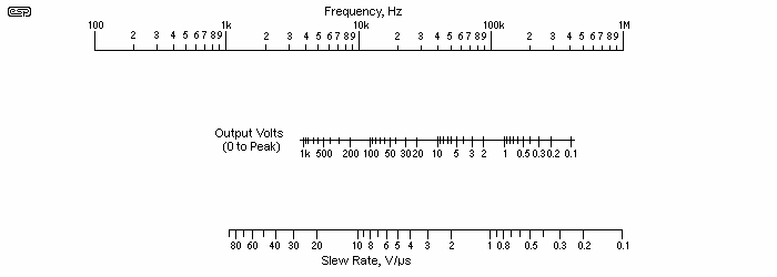
Figure 4 - Slew Rate Nomograph
Slew rate distortion is caused when a signal frequency and amplitude is such that the amplifier is unable to reproduce the signal as a sine wave. Instead, the input sine wave is 'converted' into a triangle wave by the amplifier. This is shown in Figure 5, and is indicative of this behaviour in any amplifier with a limited slew rate. The basic problem is caused by the 'dominant pole' filter included in most amplifiers to maintain stability and prevent high frequency oscillation. While very few amplifiers even come close to slew rate induced distortion (AKA Transient Intermodulation Distortion) with a normal signal, this is one of the very few possibilities left to explain why some amps seem to have a less than enthusiastic response from the reviewers' perspective.
If you don't like the nomograph, you can calculate the maximum slewrate if a sinewave easily. The formula is ...
SR = 2π × f × Vp
Where SR is slewrate in V/s and Vp is the peak voltage of the sinewave (VRMS × 1.414)
For example, 20kHz at 28V RMS (100W/ 8 ohms) requires a slewrate of ...
SR = 2π × 20,000 × 40
SR = 5,026,548 V/s = 5.03V/µs
We already know absolutely that no music source will ever provide a full power signal at 20kHz, but to allow it the amp needs a slewrate of 5V/µs (close enough). Should someone claim that you need 100V/µs or better, that their amp can do just that and you'll miss out on much of your music, then you know that the claims are fallacious. Having a higher slewrate than strictly necessary does no harm, provided that the design's stability hasn't been compromised to achieve the claimed figure. All design is the art of compromise, and some compromises can be a giant leap backwards if the designer concentrates on one issue and ignores others. I happen to think that stability is extremely important - no amp should oscillate when operated normally into any likely speaker load ... ever!
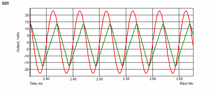
Figure 5 - Slew Rate Limiting In An Amplifier
The red trace shows the amp operating normally, and the green trace shows what happens if the slew rate is deliberately reduced. Is this the answer, then? I wish it were, since we could all sleep soundly knowing exactly what caused one amp to sound the way it did, compared to another, which should have sounded almost identical.
A further test is to apply a low frequency square wave at about half to 3/4 power, mixed with a low-level high frequency sinewave to the amplifier. At the transitions of the squarewave, the sinewave should simply move up and down - 'riding' the squarewave. If there is any misbehaviour in the amp, the sinewave may be seen to be compressed so its shape will change, or a few cycles may even go missing entirely. Either is unacceptable, and should not occur.
This is an extremely savage test, but most amplifiers should be able to cope with it quite well. Those that don't will modify the music signal in an unacceptable way in extreme cases (which this test simulates). Again, this is an uncommon test to perform, but may be quite revealing of differences between amps.
Frequency And Slew Rate Distortion - Synopsis
We need to delve deeper, and although there seems to be little (if any) useful evidence we can use to explain this particular problem, there is an answer, and it therefore possible to measure the mechanism that causes the problem to exist.
The performance of a feedback amplifier is determined by two primary factors. These are
If the amp has a poor open loop gain and high distortion, then sensible amounts of feedback will not be able to correct the deficiencies, because there is not sufficient gain reserve. By the time the performance is acceptable, it may mean that the amplifier has unity gain, and is now impossible to drive with any normal preamp.
Many amplifiers have a very high open loop gain, but may have a restricted frequency response. Let's assume an amp that has a gain of 100dB at 20Hz, and 40dB gain at 20kHz. If we want 30dB of overall gain (which is about standard), then there is 70dB of feedback at 20Hz, but only 10dB at 20kHz. As a very rough calculation, distortion and output impedance are reduced by the feedback ratio, so if open loop distortion were 3% (not an unreasonable figure), then at 20Hz, this is reduced to 0.0015%, but will be only just under 1% at 20kHz.
Because these figures are so rarely quoted (and I must admit, I have not really measured all the characteristics of the 60W amp in Project 03 - open loop measurements are difficult to make accurately), we have no idea if amplifiers with poor open loop responses are responsible for so many of the failings we hear about. It is logical to assume that there must be some correlation, but we don't really know for sure.
Ideally, an amplifier should have wide bandwidth and low distortion before global feedback is applied, which will just make a good amp better. Or will it? I have read reviews where a very simple amp was deemed one of the best around (this was quite a few years ago), and I was astonished when I finally saw the circuit - it was almost identical to the 'El Cheapo' amplifier (see the projects pages for more info on this amp).
The only major difference between this amp and most of the others at the time was the comparatively low open loop gain, and a somewhat wider bandwidth than was typical at the time, because it does not need a Miller capacitor for stability. So the amp was better in one respect, worse in another.
In the end, it doesn't really matter what the open loop response is like, as long as closed loop (i.e. with feedback applied) performance does not degrade the sound. Again, we have the same quandary as before - unless we can monitor the difference between input and output at all levels and with normal signal applied, we really don't know what is going on. The usual tests are useful, but cannot predict how an amp will sound. I have heard countless stories about amps that measure up extremely well, but sound 'hard and dry', and have no 'music' in them.
Unless these measurements are made (or at least some modified form), we will still be no further in understanding why so many people prefer one brand of amp over another (other than peer pressure or advertising hype).
One possibility is to measure the amp with a gain of 40dB. This is an easy enough modification to make for testing, and the performance is far easier to measure than if we attempt open loop testing. The difference between measured performance at 30dB gain (about 32) versus 40dB (100) would be an excellent indicator of the amp's performance, and it is not too hard to predict the approximate open loop response from the different measurements. To be able to do this requires that all measurements be very accurate.
Would these results have any correlation with the review results? We will never know if someone doesn't try it - work the techniques discussed here thoroughly, with a number of different amps. It would be useful to ensure that the reviewer was unaware of the test results before listening, to guard against experimenter expectancy or sub-conscious prejudice.
It is very hard to do a synopsis of this topic, since I have too little data to work with. Only by adopting new ideas and test methods will we be able to determine if the 'golden-ear' brigade really does have golden ears, or that they actually hear much the same 'stuff' as the rest of us, but have a better vocabulary. That is not intended as a slur, just a comment that we have to find out if there is anything happening that we (the 'engineering' types) don't know about, or not. Unless we can get a match between measured and described performance, we get nowhere (which is to say that we stay where we are, on opposite sides of the fence).
Many is the claim that the ear is one of the most finely tuned and sensitive measuring instrument known. I am not going to dispute this - not so that I will not offend anyone (I seem to have done this many times already), but because in some respects it is true. Having said that, I must also point out that although extremely sensitive, the ear (or to be more correct, the brain) is also easily fooled. We can imagine that we can hear things that absolutely do not exist, and can just as easily imagine that one amplifier sounds better than another, only to discover that the reverse is true under different circumstances. Listeners have even declared one amp to be clearly superior to another when the amp hasn't been changed at all.
Could it be the influence of speaker cables, or even loudspeakers themselves? This is quite possible, since when amps are reviewed it is generally with the reviewer's favourite speaker and lead combination. This might suit one amplifier perfectly, while the capacitance and inductance of the cable might cause minute instabilities in other otherwise perfectly good amplifiers. Although it a fine theory to suggest that a speaker lead should not affect the performance of a well designed amplifier, there are likely to be some combinations of cable characteristics that simply freak out some amps. Likewise, some amps just might not like the impedance presented by some loudspeakers - this is an area that has been the subject of many studies, and entire amplifiers have been designed specifically to combat these very problems [ 1 ].
Many published designs never get the chance of a review, at least not in the same sense as a manufactured amplifier, so it can be difficult (if not impossible) to make worthwhile comparisons. In addition, we sometimes have different reviewers making contradictory remarks about the same amp. Some might think it is wonderful, while others are less enthusiastic. Is this because of different speakers, cables, or some other influence? The answer (of course) is that we have no idea.
We come back to the same problem I described earlier, which is that the standard tests are not necessarily appropriate. A frequency response graph showing that an amp is ruler flat from DC to daylight is of absolutely no use if everyone says that the highs are 'veiled', or that imaging is poor. Compare this with another amp that is also ruler flat, and (nearly) everyone agrees that the highs are detailed, transparent, and that imaging is superb.
We need to employ different testing methodologies to see if there is a way to determine from bench (i.e. objective) testing, what a listening (i.e. subjective) test might reveal. This is a daunting task, but is one that must be sought vigorously if we are to learn the secrets of amplifier sound. It is there - we just don't know where to look, or what to look for ... yet. Until we have correlation between the two testing methods, we are at the mercy of the purveyors of amplifier snake oil and other magic potions.
The SIM distortion indicator is one possible method that might help us, but it may also react to the wrong stimulus. Perhaps we need to add the ability to detect small amounts of high frequencies with greater sensitivity, but now a simple idea becomes quite complex, possibly to no avail. It is also important that such a device has zero effect on the incoming signal itself, so some care is needed to ensure that there is negligible loading on the source preamplifier.
This is not the only avenue open to us to correlate subjective versus objective testing. Both are important, the problem is that one is purely concerned with the way an amplifier behaves on the test bench, and a whole series of more or less identical results can be expected. The other is veiled in 'reviewer speak', and although it might be useful if the reviewer is known and trusted, is not measurable or repeatable. The whole object is to try to determine what physical factors cause amplifiers to sound different, despite that fact that conventional testing indicates that they should sound the same.
The output impedance of any amplifier is finite. There is no such thing as an amplifier with zero output impedance, so all amps are influenced to some degree by the load. An ideal load is perfectly resistive, and has no reactive elements (inductance or capacitance) at all. Just as there is no such thing as a perfect amplifier, there is also no such thing as a perfect load. Speakers are especially gruesome in this respect, having significant reactance, which varies with frequency.
A genuine zero impedance source is completely unaffected by the load, and it does not matter if it is reactive or not. If such a source were to be connected to a loudspeaker load, the influence of the load will be zero, regardless of frequency, load impedance variations, or anything else. It's worth mentioning that by clever manipulation of feedback, it is (theoretically) possible to achieve zero output impedance (and even negative impedance which I have done in a test amp I use in my workshop). The problem is that doing so involves a small amount of positive feedback, which is inherently unstable. All amps normally have a low but measurable positive (i.e. 'normal') output impedance, but it's possible that internal wiring can be mis-routed such that an amplifier does have a small amount of negative impedance. Poor grounding practices can achieve this, and it's definitely not something to aim for!
Since true zero impedance is not the case in the real world, the goal is generally to make the amplifier have the lowest output impedance possible (but remaining positive at all times), in the somewhat futile hope that the amp will not be adversely affected by the variable load impedance. In essence, this is futile, since there will always be some output impedance, and therefore the load will always have some influence on the behaviour of the amp.
Another approach might be to make the output impedance infinite, and again, the load will have zero effect on the amplifier itself (the amplifier will, however, have a great influence on the load!). Alas, this too is impossible. Given that the conventional approaches obviously cannot work, we are faced with the problem that all amplifiers are affected by the load, and therefore all amplifiers must show some degree of sensitivity to the speaker lead and speaker.
The biggest problem is that no-one really knows what an amplifier will do when a reactive load reflects some of the power back into the amp's output. We can hope (without success) that the effects will be negligible, or we can try to make speakers appear as pure resistance (again, without success).
A test method already exists for this, and uses one channel of an amp to drive a signal back into the output of another. The passive amplifier is the one under test. It is also possible to use a different source amplifier altogether, since there is no need for it to be identical to the test amp. Use of a 'standard' amplifier whose characteristics are well known is useful, since the source will be a constant in all tests. Differences may then be seen clearly from one test to the next.
The method is shown in Figure 6, and is a useful test of the behaviour of an amp when a signal is driven into its output. This is exactly what speakers do - the reactive part of the loudspeaker impedance causes some of the power to be 'reflected' back into the amplifier. Since one amplifier in this test is the source, the device under test can be considered a 'sink'.
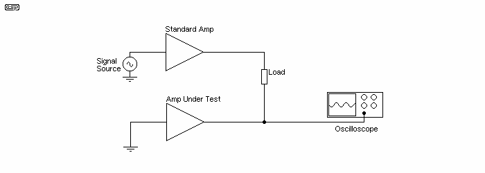
Figure 6 - Amplifier Power Sink Test
I have used this test, and although it does show some interesting results, the test is essentially not useful unless used as a comparative test method. The amplifier under test is also subjected to very high dissipation (well above that expected with any loudspeaker load), because the transistors are expected to 'dump' a possibly large current while they have the full rail voltage across them. There is a real risk of damaging the amplifier, and I suggest that you don't try this unless you are very sure of the driven amplifier's abilities.
We may now ask "Why is this not a standard test for amplifiers, then?" The answer is that no-one has really thought about it enough to decide that this will (or should) be part of the standard set of tests for objective testing of an amplifier. The results might be quite revealing, showing a signal that may be non-linear (i.e. distorted), or perhaps showing a wide variation in measured signal versus frequency. The result of this test with amps having extensive protection circuits will be a lottery - most will react (often very) badly at only moderate current.
If there is high distortion or a large frequency dependence, then we have some more information about the amplifier that was previously unknown. It might be possible to correlate this with subjective assessments of the amp, and gain further understanding of why some amps supposedly sound better than others. We might discover that amps with certain characteristics using this test are subjectively judged as sounding better than others ... or not.
If this test became standard, and was routinely allied with the SIM tester described above, we may become aware of many of the problems that currently are (apparently and/or allegedly) audible, but for which there is no known measurement technique.
This article has described some tests that although not new, are possibly the answer to so many questions we have about amplifiers. The tests themselves have been known for some time, but their application is potentially of benefit. We may be able to finally perform an objective test, and be able to predict with a degree of confidence how the amp will sound. It may also happen that these tests are not sufficient to reveal all the subtleties of amplifier sound, but will certainly be more useful than a simple frequency response and distortion test.
Any change to the testing methods used is not going to happen overnight, and nor are we going to be able to see immediately which problems cause a difference, and which ones have little apparent effect. Time, patience, and careful correlation of the data are essential if this is to succeed. There are laws of physics, and there are ears. Somewhere the two must meet in common ground. We already know that this happens, since there are amplifiers that sound excellent - according to a large number of owners, reviewers, etc. - now we need to know why.
There is a test method (or a series of methods) that will allow us to obtain a suite of tests that makes sense to designers and listeners alike, so we can get closer to the ideal amplifier, namely the mythical 'straight wire with gain', but from the listener perspective rather than the senseless repetition of tests that seem to have no bearing on the perceived quality of the amp. This is not to say that the standard tests are redundant (far from it), but they do not seem to reveal enough information.
For this to succeed, the subjectivists must be convinced, as must the 'objectivists'. We are all looking for the same thing - the flawless reproduction of sound - but the two camps have drifted further and further apart over the years. This is not helped by the common practice of reviewers to connect everything up themselves, and rely not just on the sound, but their knowledge of which amplifier they are listening to. Sighted tests are invariably flawed, and the only test methodology that should ever be used is a full blind or double-blind test, with the ability to switch from one amplifier to the other, but without knowing which is which.
These are my musings, and I am open to suggestions for other testing methods that may reveal the subtle differences that undeniably exist between amplifiers. At the moment we have a chasm between those who can (or think they can) hear the difference between a valve and an opamp, a bipolar junction transistor and a MOSFET, or Brand 'A' versus Brand 'B', and those who claim that there is no difference at all.
The fact that there are differences is obvious. The degree of difference and why there are differences is not. It would be nice for all lovers of music (and the accurate reproduction of same) if we can arrive at a mutually agreeable explanation for these differences, that is accurate, repeatable, and measurable.
If these criteria are not met, then the assessment is not useful to either camp, and the chasm will simply widen. This is bad news - it is high time we all get together and stop arguing amongst ourselves whether (for example) it is better to use one brand of capacitor in the signal path or another. The continued use of sighted test procedures does nothing to advance the state of the art.
These testing methods can also be applied to the measurement of individual components, speaker cables, interconnects and preamps, particularly the SIM tester. Using the amplifier power sink test with different cables and speakers might give us some clues as to why so many people are adamant that one speaker cable sounds better than another, even though there is no measurable difference using conventional means.
The greatest benefit of these tests is that they will reveal things we have not been looking at (or for) in the past, and may show differences that come as a very great surprise to designers and listeners alike.
Another very useful test is a 'null test', as proposed by Ethan Winer. For example, a signal is applied simultaneously to two leads. and the tester adjusted until there is nothing left of the original signal. If a complete null can be achieved, the two leads are essentially identical. If it were otherwise, it would not be possible to achieve a null, and the original signal will still be present, either as a distorted version of the original, or a low-level version of the original. This is not new - It was used by Peter Baxandall and Peter Walker (Quad) many years ago, but it's not trivial when measuring active circuits. This is mainly due to tiny phase shifts that are very hard to duplicate perfectly.
For information on the use of the SIM, and an initial article describing how it works and my results so far, please see 'Sound Impairment Monitor - The Answer?'.
Main Index
Articles Index