
|
|
| Elliott Sound Products | Earthing Your Hi-Fi - Tricks and Techniques |
 Main Index
Articles Index
Main Index
Articles Index
It is not uncommon to see hi-fi equipment with the earth (ground) disconnected from one piece of equipment or another, usually to prevent a hum loop which ruins the listening experience. However, there is nothing quite like being electrocuted to really ruin the experience should something go wrong!
First, a quick word on electrocution. It is not fun, and electricity kills a great many people worldwide every year. A current of 50mA (barely enough to make a low wattage lamp even glow) is sufficient to send your heart into a state called 'ventricular fibrillation', where the heart muscles are all working out of synchronisation with each other. Little or no blood is pumped, and you will die within about 3 minutes unless help is immediately at hand.
Sometimes (but less often), your heart will simply stop. If this happens, it is possible that with external heart massage that it might re-start, and occasionally it might even re-start by itself - rare, but it can happen. The result of fatal electrocution is that you will no longer be able to enjoy the hi-fi that you have spent so much time and money putting together, and all other earthly activities are similarly curtailed. 
Note that the word 'electrocute' literally means to kill with electricity. You may survive an electric shock, but unless help is at hand, you will not survive electrocution.
This article has been prompted by many e-mails I have received asking about hum, earthing and what should be done to ensure that equipment is safe, and does not hum. There are other causes of hum in a sound system other than electrical (safety) earthing issues, but I will contain this particular article to the basic issues of safety and eliminating hum loops while maintaining a high degree of safety.
 |
The regulations regarding safety earth connections vary from one country to the next, and I do not have the details for each case. This article is general, and if unsure, you
should consult the appropriate electrical supply authority in your country to obtain the rules that apply to you. I have used the terminology I am familiar with - the live conductor is called the 'active' and the return conductor is called 'neutral'. The safety conductor is called 'earth' or sometimes 'earth ground' (particularly in the US). These terms differ, so make sure that you know what they are called where you live. |
The basic idea of an electrical safety earth (or ground) is pretty much the same everywhere, but the details can vary widely. The case (chassis) of the equipment (and except for special situations, the internal electronics) is connected to an earth pin on the mains outlet. This is then connected through the house wiring and switchboard to an electrically solid earth point, which is commonly a copper water pipe (no longer allowed in Australia or NZ), or an approved earth stake buried deep into the ground.
In some systems used elsewhere, the earth wire is separate back to the distribution transformer, and in others the neutral is also the earth up until the household switchboard. Australia and New Zealand use the 'Multiple Earth Neutral' (MEN) system, where there is a bond between neutral and earth at each household (or unit complex) main switchboard. The maintains the lowest possible impedance for the safety earth. Other countries have different regulations and systems - look it up for your location or ask an electrician if unsure.
Should a fault develop within the equipment that causes the active (live) conductor to come into contact with the chassis, the fault current will flow to earth, and the equipment or main switchboard fuse or circuit breaker will blow. This protects the user from electric shock, bypassing the dangerous current directly to earth, rather than through the body of the unsuspecting poor bastard who just touched it. If this experience does not kill, it will invariably enrich the vocabulary.
Earth leakage circuit breakers (aka RCDs - residual current detectors - see below) measure the current in the active and neutral conductors. If these differ by more than a few milliamps, the circuit is disconnected. The principle is simple - if the current in the two wires differs, some of it must be going somewhere that is undesirable, so the supply is interrupted almost instantly. While these are mandatory in some countries (or under some circumstances), it is best not to rely on any advanced technique, but provide a system that is 100% electrically safe - this can be extremely difficult in reality.
There are exceptions to the basic earthed equipment method of protection. Some equipment is designated 'Double Insulated', and usually has a symbol of two concentric squares that indicates that the equipment is double insulated, and that an earth connection is not needed (or in some cases must not be used). The common plug-pack (wall-wart) power supply is nearly always double insulated, and such equipment has reinforced insulation, designed to ensure that it is not possible for the live AC connection to connect to the secondary electronics in any event - including a complete meltdown. The electrical safety tests to verify that a product meets the Double Insulation standards are rigorous and expensive, and are very difficult to meet with high powered equipment, and even more so when the equipment has a metal case. Nearly all power amplifiers (for example) are not double insulated, and require an earth connection.
The common colour codes for mains wiring are shown in Table 1, below. The Active (or Line) is the 'hot' conductor, and carries the full AC supply voltage. The Neutral conductor is not live, but is intended to be the return path for all current in the active lead. The neutral is always considered to be a 'live' conductor and must be insulated accordingly, and it must not be used for anything other than the return path for current from the active. Although this has caused great confusion to a great many people, it is sensible and logical (I will not go into the reasons here). The safety earth (or ground) conductor is intended to provide protection against electrocution, and where fitted, must not be disconnected.
| Conductor | IEC | US | Alternative |
| Active (Line, Live, Hot) | Brown | Black | Red |
| Neutral | Blue | White | Black |
| Earth | Green/Yellow | Green | Green |
These colour codes are not standardised, and some variations may be found in different countries. The column headed 'Alternative' refers to an old code that used to be used in Australia and several other countries prior to the IEC codes being adopted. The one common theme of these codes is that they have been designed so that colour-blind people will not get the wires mixed up. The use of green with yellow stripes for the earth makes this even more secure. I have no information on the history of the determination of the colours used, but it is of little consequence since we can't change it.
Note that in the US, the neutral is sometimes referred to as the groundED conductor, and earth/ earth ground called the groundING conductor. These terms are not intuitive and are easily mixed up if you don't understand the difference. Make sure that you fully understand all terms that are used where you live.
Figure 1 shows a typical connection of two hi-fi components, and includes the house wiring and main earthing point. As can be seen, there is a loop (indicated by the dotted line), which includes the interconnect cable, power leads, and a small part of the house wiring. Such loops are a major cause of hum in systems, and it is not uncommon for people to remove an earth wire from one or the other mains connectors to break the loop and stop the hum. The situation is much worse if different wall outlets are used for different parts of the sound system. In this case, the loop may extend all the way back to the main switchboard, making it longer, and more likely to have a significant voltage between individual earth connections.

Figure 1 - The Formation of an Earth Loop
Also note that the neutral (return) conductor is attached to earth at the main switchboard. This is called the MEN system and is standard in Australia and some other countries, but might not be the case where you live. Check with an electrician who can tell you how this is done (if you really want to know).
What happens if the amplifier develops an electrical fault that allows the live AC conductor to come into contact with the chassis? The current will flow from the chassis, through the earth connection, and the fuse/ circuit breaker will blow in the switchboard (or in the equipment if a mains fuse is fitted).
Should the safety earth be disconnected from the power amp (for example), if a fault occurs in the amp, the only earth return is now via the interconnects (assuming that the source is earthed). Interconnects are not designed to withstand the fault current that can occur with a major electrical fault, and may disintegrate before the fuse. You now have a live chassis on the amplifier - just waiting for someone to touch it and possibly die!
Many new installations use a safety switch, specifically an 'Earth Leakage' or 'Residual Current' detector (aka GFI - ground fault interrupter, etc.), a device that will disconnect the AC supply if the current flowing in the active (live) conductor is not exactly matched by that in the neutral. Any imbalance means that current is going somewhere it should not be, and the device will trip.
These safety circuit breakers are very fast acting, and have saved many lives since their introduction. The 50mA that will kill you is detected by the breaker, and the power is disconnected - fast! Most of these type of breakers will operate on as little as 20mA, so you are not only protected against major faults, but also against excessive AC leakage caused by faulty insulation or moisture.
This does not mean that you can now go around disconnecting earth connections to stop hum - the safety devices that may be fitted to your house wiring are designed to trigger on a fault before you find it the hard way. In many countries, it is illegal to tamper with electrical (mains) wiring unless you are licensed - but in all countries, if it can be proven that you disconnected an earth that allowed a fault to kill someone else, you are liable, and may be subject to criminal charges ! Is that scary?
It is generally accepted that an earth loop conducts a current from one piece of equipment to the next, and imposes a voltage across the connection. A good question is where does the current come from, and why doesn't it trip the safety switch? Contrary to common belief, earth loops are not caused by leakage current or some other mysterious current that flows in the earth lead back to the switchboard. If this were the case, it would have to be coming from an active connection via a leakage path, and this would trip the safety switch instantly.
The loop is mostly entirely local, and (again) contrary to some claims, connecting equipment to separate mains outlets will almost certainly make the situation much worse. Current in the local loop is created by the stray magnetic field of transformers in the connected equipment. Traditional (EI) laminated transformers are almost always worse in this respect than toroidal transformers, but all mains frequency transformers are capable of generating a circulating current if given the opportunity. These currents are made worse if there is metal chassis work in close proximity to the transformer laminations. Thick panels simply mean lower resistance, so a higher current flows for a given induced voltage.
Another source is a signal lead running parallel to a mains power lead. Although the conductors of mains leads are twisted, the twist is usually fairly basic, so balancing of the magnetic field is rather poor compared to the tight twist of Cat-5 communications cable for example. The magnetic coupling is poor, and the greatest problems are likely to be caused by capacitive coupling. Since this favours high frequency noise, the sound is completely different from an earth loop, and it's a good idea to try to familiarise yourself with the different sounds made by the various issues that may plague hi-fi setups. If signal cables and mains wiring must cross each other, ensure they cross at right angles, and if possible separate the two as far as practicable. Capacitive coupling can also be an issue with transformer windings, where mains noise is coupled through to the secondary by inter-winding capacitance, or from Y-Class caps from mains to chassis.
It is not at all uncommon that multiple earth loops may exist, but in the vast majority of cases a transformer is the root cause of the problem. The loop created by the mains safety earth and the various interconnects can be quite large, and it may not seem possible that cables so far from a transformer could possibly generate enough current to cause a problem. However, the cables might well be separated, but what about the equipment chassis? Any metal panel that passes close to the transformer becomes part of the problem too, depending on how the internal earthing connection is arranged. It's not uncommon to see the mains safety earth connected near the mains inlet, and the signal earth connected somewhere else on the chassis. In isolation, this will never cause a problem. Once the equipment is connected to something else that's also earthed, an instant earth loop is created.
While disconnecting the mains earth from one of the offending pieces of kit may well break the loop, it also renders the setup unsafe if there is an internal fault. In some countries, it may be illegal to disconnect a safety earth, and if someone is killed or injured you may be held liable.

Figure 2 - Transformer Induced Earth Loop Current Waveform
The waveform shown above was not simulated. It was captured on a PC based oscilloscope, using a single loop of thin wire (loosely) around the outside of an E-I core transformer. No special attempt was made to optimise the signal, and the loop was terminated by a resistor of 0.22 ohms. The voltage was changed only very slightly regardless of whether the resistor was connected or not, showing that it is not unreasonable to expect that the current may be very large indeed if the impedance of the loop is low enough. Note that the primary frequency is 50Hz, but the waveform shows that there is a very high level of 150Hz ... the third harmonic.
Remember that any metalwork, including that of another piece of equipment sitting above that which uses the transformer, becomes part of this loop. Increasing the size (effective diameter) of the loop does reduce the problem slightly, but the larger loop may also be more sensitive and need less magnetic flux to generate a potentially troublesome voltage and current.
Although the measured voltage of the waveform in Figure 2 is only about 20mV, compare this with the signal voltage at a typical listening level. Assuming speakers at around 90dB/W/m and a power amp gain of 27dB, the hum is only 15.7dB below a listening level of 1W (90dB SPL at 1 metre). This will be very audible indeed.
For those who build amps (as is the case with many of the readers of these pages), a common question is "How should I connect the mains safety earth to the chassis?". As I stated above, the regulations change from one country to the next, but the principles are the same. Figure 3 shows a view of the basic connection, which is very safe. The lug used should be an approved earth lug (or one that meets any standards that exist where you live). Most are crimped, but soldering ensures the most reliable connection for safety.
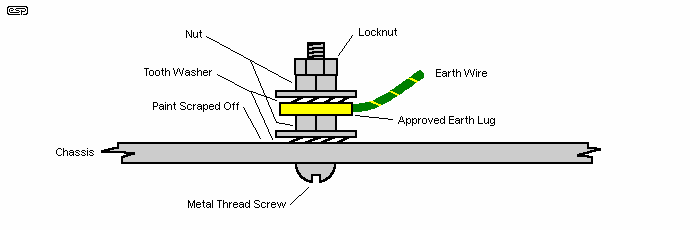
Figure 3 - Safe Method Of Connecting The Safety Earth
Any paint (or anodising, in an aluminium chassis) must be scraped away to expose bare metal, and the tooth washer ensures that there is a good 'bite' into the metal itself. The use of two nuts is strongly recommended, since the second one acts as a locknut, and prevents the first nut from loosening. The flat washers shown are optional, but highly recommended. They may be a requirement in some countries.
Do not use the earth connection as mounting for any other panel or component - it must be dedicated to the task of providing a safety earth point. If a component mounting bolt is used, at some stage it may be disconnected by a service (or other) person, which means that the apparatus is unsafe until everything is (hopefully) put back where it belongs - this does not always happen.
Make sure that the electrical connection between metal panels is also very well made. Some chassis are available in a kit form, and when screwed together, may not make good electrical contact with each other. Should the mains come in contact with a panel that has a flaky connection with the one that is earthed properly, the same potential for disaster is still present. All exposed metal must be properly and securely earthed.
The internal electronics of an amplifier should also be earthed, but now we have the problem of the hum loop again. There are two possibilities here ...
Power supplies are usually earthed to the chassis, but in some cases the DC side may be left floating, or grounded using a loop breaker (see next section). The important part is exactly where you choose to join the supply zero volt (earth/ ground) point to the chassis. With any power supply, the transformer's centre tap (assuming a split (positive and negative) power supply) joins to the filter capacitor bank. In all cases, the final earth point is from the centre tap of the capacitors, or from the output end of a regulated supply using P05 or P05-Mini PCBs (for example).
If you join the transformer's centre tap to the chassis, you will almost always get some hum or buzz. Even the smallest amount of PCB track or heavy gauge wiring introduces some resistance and/ or impedance, and because of high peak current this can have a surprisingly large effect on the outcome. This isn't an earth loop issue, it's simply caused by an inappropriate connection to the chassis.
So, not all hum/ buzz is the result of an earth loop - even 50mm of wire or PCB trace can be more than enough to cause (sometimes) serious problems. It's important to understand that just because a point on a schematic is indicated as earth/ ground, this never means that all such points on the schematic are truly equal. When you have comparatively high peak currents with a physical resistance/ impedance between the source (the transformer) and the output (filter capacitors or regulators), there will be a voltage developed between the two points. If your earth reference is the noisy end (the transformer), then you will have problems.
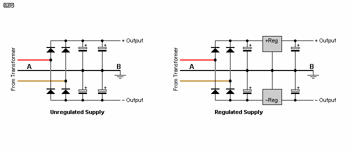
Figure 4 - Correct Earthing Point For Power Supplies
The important thing to recognise is that points 'A' and 'B' are not the same. The schematic shows them to be equivalent (as do all schematics), but there is resistance and inductance between the two points. Even with a rather miniscule 10mΩ (that's 10 milli-ohms) and 1µH of inductance between the two caps in the regulated circuit, you can get 42µV of noise across the two points shown. That's with a load of less than 50mA. With a power amplifier supply, that gets a lot worse because the peak current is very high, and the load is constantly varying. The correct earthing point is that shown at 'B' in both cases.
While very effective (and safe), as mentioned above such a circuit might not be legal where you live. If this is the case and hum is causing you grief, the use of balanced interconnects might solve the problem - but at some cost, and will require balancing circuitry at each end of all the interconnects. While not a panacea, this is the approach taken in all professional equipment, and is usually highly effective, allowing all safety earth connections to remain exactly as they are to prevent electrocution of the artists or road crew. Suitable circuits for home (or professional) use are shown in the projects section.
Note that there is an ongoing debate about the proper connection of pin 1 of all XLR connectors, and if not done appropriately for the equipment, the "pin 1 problem" may either defeat any benefit from balancing or even make matters worse. In nearly all cases, transformers are more effective than electronically balanced circuits, but good ones come at high cost, and cheap ones may seriously affect the frequency response of the equipment.
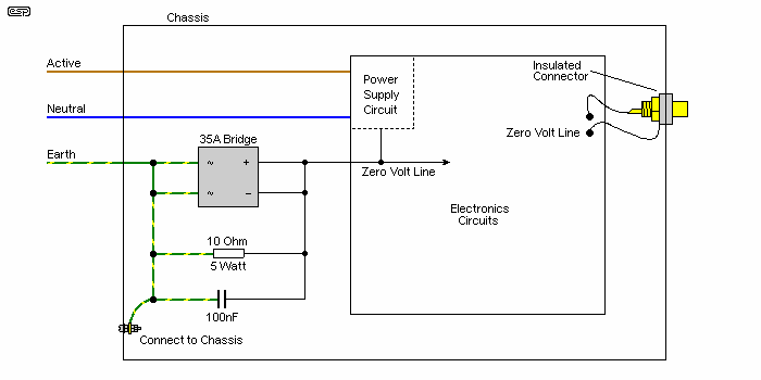
Figure 5 - A High Current Safety Loop Breaker Circuit
I have simply shown all internal electronics as a box, with the only connection to the loop breaker being the zero volt line. This is most commonly taken directly from the centre tap of the main amplifier filter capacitors, but should always be connected to a point where there is high current wiring back to the transformer. It is the transformer that provides isolation from the mains, and the possibility of an internal transformer fault must be catered for. Ideally, the mains earth connection and the loop-breaker's earth end should connect to the same point on the chassis (as shown). Depending on the installed transformer, there may be a significant circulating current within the chassis itself.
The only exception is if a double insulated mains transformer is used, but these are rare. Should the transformer be of 'conventional' construction (not a toroidal), then the transformer body - the steel core - must be connected to chassis directly. Do not use any loop breaker circuit to isolate the transformer core, as it is unnecessary and dangerous to do so.
The loop breaker works by adding a resistance in the earth return circuit. This reduces circulating loop currents to a very small value, and thus 'breaks' the loop. The capacitor in parallel ensures that the electronics are connected to the chassis for radio frequency signals, and helps to prevent radio frequency interference. Finally, the diode bridge provides the path for fault currents. The use of a large chassis mounting (35A) type is suggested, since this will be able to handle the possibly very high fault currents that may occur without becoming open circuit. Note the way the bridge is wired, with the two AC terminals shorted, and the two DC terminals shorted. Other connection possibilities are dangerous, and must be avoided.
In the event of a major fault, one (or more) of the diodes in the bridge will possibly fail. Semiconductors (nearly) always fail as short circuit, and only become open circuited if the fault current continues and 'blows' the interconnecting wires. High current bridge rectifiers have very solid conductors throughout, and open circuit diodes are very rare (I have never seen a high power bridge go open circuit - so far at least). Use of the bridge means that there are two diodes in parallel for fault current of either polarity, so the likelihood of failure (to protect) is very small indeed.
When a loop breaker is used, it is vitally important that all input and output connectors are insulated from the case. If not, they will instantly defeat the loop breaker by providing a direct connection from the zero Volt point to chassis, and no benefit is obtained. (Electricity has an annoying - but perfectly logical - tendency to travel along the path of least resistance, and a direct short circuit will always have less resistance than the loop breaker.)
It is not uncommon to have an induced voltage of perhaps 1V RMS between the earth connections of power outlets that are wired separately back to the switchboard. This small voltage, with a total resistance of perhaps 0.2-0.5 Ohm, will cause a loop current of 2 to 5 Amps, all of which flows in the shield of the interconnect. This is sufficient to cause a voltage difference across the interconnect, which the amplifier cannot differentiate from the wanted signal. By breaking the loop with the 10 Ohm resistor, the current is now less than 200mA, and the voltage across the interconnect will be very much smaller, reducing the hum to the point where it should no longer be audible.
Never route an earth wire to the main (star) earthing point on a chassis in such a way that it forms a partial (or full) turn around a transformer. It is better to relocate either the star earth point or the transformer to ensure that no earth conductor can create a partial turn. There may often be conflicting requirements, but there is usually no reason that proper earthing for minimum hum and maximum safety should be mutually exclusive. Both are important, and both must be accommodated in the final design.
|
An earth loop will typically inject either a 50Hz or 60Hz hum into the signal, or in the (common) case of a transformer induced current, a somewhat mangled mains frequency as shown in Figure 2 - if you have a 100Hz or 120Hz buzz (which generally has a hard edge to the sound), you have done something wrong in the wiring of the power supply, and the techniques described here will not help. Refer to the article on power supply wiring. |
The core of the transformer (only for C-core or EI types - it's not accessible with toroidal transformers) should also connect to the chassis and mains earth. In the unlikely event of a primary to core leakage or short circuit, the current will be diverted to the protective earth and will trip the safety switch or circuit breaker. In some cases, a transformer may be fitted with an electrostatic shield, but these are lamentably uncommon in hi-fi transformers. Where provided, these too should be connected directly to the main earth point, and not via a loop breaker (if used).
The purpose of the electrostatic shield is to intercept (and earth) any interference on the incoming mains. It does this by preventing any signal from being capacitively coupled from the primary to secondary windings, so the only form of coupling in the transformer is via the magnetic field in the transformer core. Most mains transformers have relatively poor high frequency response and this helps to further reduce interfering signals.
This can dramatically reduce extraneous noises (clicks, pops, whirring sounds, etc.) that might get into the system via the house and supply company wiring. This has great potential to pick up noise, since there may be 50 to 100km (or more) of cable (including high voltage feeders and substations) involved between your amplifier and the generating plant.
In some cases, a mains filter might be fitted to amplifiers or other equipment (such as specially designed mains leads or 'black boxes') to reduce any interference. Where fitted, if an earth connection is provided, it must be connected to the safety earth and chassis - never to the amp's zero volt line. Typical filters will use Metal Oxide Varistors (MOVs) to cut off any high voltage spikes, and a capacitor and inductor network to filter out anything that is not at the mains frequency.
A true 50Hz (or 60Hz) tuned filter will be a large unit indeed, so most line filters only work at frequencies above a few kHz. This is generally enough to get rid of most interference, since a well designed power supply should be able to filter out the majority of noise from the mains. Mains filters usually use the mains earth as a reference, so it must be present for the units to work correctly. Not using the safety earth as a reference is extremely dangerous, since the filters may have capacitors that become short circuited if a high voltage spike manages to get through and punctures the insulation.
Electrical safety cannot be over emphasised. Hum is damn annoying, and everyone wants it gone. There is no good reason to sacrifice one for the other, since safety and hum-free operation can peacefully co-exist with care and the right techniques. Use of a separate earth stake just for hi-fi equipment is probably unlawful in most countries, as the integrity of the safety earth may be suspect at best, useless at worst.
As I have said several times, make sure that you find out the legal requirements in your country, and don't do anything that places you at risk - either from electrocution or legal liability. Neither is likely to be a pleasant experience.
Where the mains is noisy (apparently a common occurrence in the US), use of a dedicated mains filter may be useful to prevent mains noise from entering the system. This will generally be unnecessary if the supply is well designed (especially if an electrostatic shield is used on the transformer), but this is often the exception, rather than the rule.
The use of 'specialty' mains leads (unless fitted with a proper filter which will be in the form of a box in line with the cable) is unlikely to solve the problem - regardless of claims made by the manufacturers or reviewers (see The Truth About Cables, Interconnects and Audio in General for my comments on these - this article made a lot of audiophiles very unhappy, but advertising hype does not negate the laws of physics).
The (relatively) recent trend to use switchmode power supplies in consumer equipment, along with double insulation, has created new problems. All SMPS use small (and allegedly) 'fail-safe' Y-Class capacitors to the chassis, which is not earthed. Use of these caps means that the chassis floats at roughly half the mains voltage, but the impedance is very high. This poses two risks ...
It might be possible to reduce this noise by installing a heavy earth strap that joins each chassis. Strictly speaking, this may be completely illegal, but the rules for double insulated appliances in many countries are often stupid, and fail to address reality. Almost all modern systems will have a mixture of earthed and double insulated equipment, and any rule that states (for example) that "double insulated appliances must not be earthed" is instantly broken when the interconnects are installed. Needless to say, without the interconnects there is no point having the gear in the first place, because there's often no other way to get the signal from one unit to the other. Optical fibre is one method of course, and completely eliminates any possibility of an earth loop. This is not always a viable option.
Main Index
Articles Index